

IOWA MOLD TOOLING 14K160TH User Manual

Printed on 23 May, 2011
Manual # 99903184
14K160TH OTR Body & Air
Compressor
Commander IV OTR Body & Compressor Parts - Specifications - Instructions
Revised 20110519
IOWA MOLD TOOLING CO., INC.
PO Box 189
Garner, IA 50438
Tel: 641-923-3711 FAX: 641-923-2424
Website: http://www.imt.com
Copyright © 2011 Iowa Mold Tooling Co., Inc.
All rights reserved
No part of this publication may be reproduced, stored in a retrieval system, or transmitted in any
form or by any means, electronic, mechanical, photocopying, recording or otherwise without the
prior written permission of Iowa Mold Tooling Co., Inc.
Iowa Mold Tooling Co., Inc. is an Oshkosh Corporation Company.


i
Contents
Introduction 3
Revisions ...................................................................................................................................................... 5
Parts - OTR Body 7
OTR Body Recommended Spare Parts ......................................................................................................... 8
Installation Kit - Body (93715891) ............................................................................................................... 9
OTR Package Assembly (51715800-1) ...................................................................................................... 11
OTR Package Assembly (51715800-2) ...................................................................................................... 12
OTR Package Assembly (51715800-3) ...................................................................................................... 13
OTR Package Assembly (51715800-4) ...................................................................................................... 14
OTR Package Assembly (51715800-5) ...................................................................................................... 15
Body Assembly (51715799-1) .................................................................................................................... 16
Body Assembly (51715799-2) .................................................................................................................... 18
Body Assembly (51715799-3) .................................................................................................................... 19
Body Assembly (51715799-4) .................................................................................................................... 21
Body Assembly (51715799-5) .................................................................................................................... 22
Body Assembly (51715799-6) .................................................................................................................... 23
DAR130 Compressor Specifications 25
Compressor Safety 29
Compressor Precautions ............................................................................................................................. 30
Compressor Safety ...................................................................................................................................... 31
Compressor Warning Decals ...................................................................................................................... 33
Compressor Instruction Decals ................................................................................................................... 35
Compressor Terminology ........................................................................................................................... 35
Description of Components ........................................................................................................................ 36
Compressor Lubrication & Maintenance 41
Lubrication and Maintenance Chart ............................................................................................................ 42
Lubricant Recommendations ...................................................................................................................... 43
Commander IV Compressor Preventative Maintenance Kit ....................................................................... 44
Compressor Maintenance Procedure .......................................................................................................... 45
Compressor Troubleshooting ...................................................................................................................... 49
Compressor Recommended Spare Parts ..................................................................................................... 52
Compressor Operation 55
Compressor Start Up/Shutdown ................................................................................................................. 55
Compressor Controls .................................................................................................................................. 56
Compressor Opera ting Conditions .............................................................................................................. 57

ii Contents
Sub-Zero Temperature Operating Instructions ........................................................................................... 58
Compressor Parts 59
Compressor Integral Components ............................................................................................................... 60
Compressor Ai r -Oil Schematic ................................................................................................................... 61
Hydraulic Schematic ................................................................................................................................... 62
Oil Cooler ................................................................................................................................................... 63
Hose Ports ................................................................................................................................................... 65
Compressor Air Inlet System ...................................................................................................................... 66
Compressor Discharge System ................................................................................................................... 67
Compressor Electrical System .................................................................................................................... 70
Wiring Diagram .......................................................................................................................................... 71
Compressor & Mounting Syste m ................................................................................................................ 72
Air Tan k ...................................................................................................................................................... 74
Murphy Latching Relay - Retrofit Kit (99903400) ..................................................................................... 75
Wiring Instructions - Murphy Latching Relay Kit (99903401) .................................................................. 77

3
C
1
HAPTER
Introduction
This volume provides information on the installation, operation, spare parts, and repair of your
Commander IV body and compressor.
WARNING
READ YOUR MANUAL!! FAILURE TO READ, UNDERSTAND AND FOLLOW ANY SAFETY
PROCEDURES APPLICABLE TO YOUR EQUIPMENT MAY RESULT IN EQUIPMENT DAMAGE,
SERIOUS INJURY, OR DEATH.
MANUAL STRUCTURE
Throughout this manual, three means are used to draw the attention of personnel. They are
NOTEs, CAUTIONs and WARNINGs and are defined as follows:
NOTE
A NOTE is used to either convey additional information or to provide further emphasis for a
previous point.
CAUTION
A CAUTION is used when there is the very strong possibility of damage to the equipment or
premature equipment failure.
WARNING
A WARNING is used when there is the potential for personal injury or death.
Use caution and common sense while operating and maintaining the crane, and follow all safety
procedures and regulations. Treat this equipment with respect and service it regularly. In
addition to reading the manual, become familiar with government regulations, hazards, and the
specific operation of your crane. Refer to ANSI/ASME B30.22, the standard for Articulating
Boom Cranes, for more information on crane design and test criteria. (You may obtain this
publication from ASME at www.asme.org.) Crane operators must also be familiar with OSHA
29CFR, Subpart N, Article 1926.550 and CAL-OSHA Title 8, Article 93 (California).
MODIFICATIONS
Modifications to your crane must be performed with IMT approved accessories, parts and
optional equipment. If in doubt about the safety, compatibility, or appropriateness of any
modifications, contact IMT prior to making those modifications. DO NOT alter or modify any
safety device! All safety devices must be inspected, tested and maintained in proper working
condition.

4 14K160TH OTR Body & Air Compressor Manual # 99903184
Note that decals regarding crane safety and operation are considered safety equipment. They
must be maintained just as any other safety device. Decals must be kept clean and legible to
the operator, operational personnel, and bystanders as specified in the decal section of this
manual. DO NOT remove, disable, or disregard any safety device attached to your crane.
The crane owner and/or designated employee is responsible for informing all operators,
maintenance personnel, and others involved in equipment operation about the safe operation
and maintenance of the crane. If questions arise, contact IMT or your IMT distributor for
clarification.
WARRANTY
Warranty of this unit will be void on any part of the unit subjected to misuse due to overloading,
abuse, lack of maintenance and unauthorized modifications. No warranty - verbal, written or
implied - other than the official, published IMT new machinery and equipment warranty will be
valid with this unit.
NOTICE TO THE OWNER / USER
If your equipment is involved in a property damage accident, contact your IMT distributor
immediately and provide them with the details of the accident and the serial number of the
equipment. If an accident involves personal injury, immediately notify your distributor and IMT’s
Technical Support at:
IOWA MOLD TOOLING CO., INC.
500 HWY 18 WEST
GARNER, IA 50438
641 - 923 - 3711

Chapter 1 Introduction 5
20070424
Manual release in new format.
20070807
51715799-2
Hardware changes.
20080904
SPARE PARTS
Fan sensor # 302899
20090105
51715799
ECN 10854 - New body weldment drawings.
20090305
51715799-3
ECN 10854 – New drawing for page 3.
PARTS
20110519
51716427
ECN 11459 - Removed chassis ground cable due to superior ground
connections in chassis.
Revisions
DATE LOCATION DESCRIPTION
20090423 51715799-1 ECN 10938 - Update body lights to LED.
20090526 COMPRESSOR
Added additional spare parts drawings.


7
Body Assembly (51715799-6) .................................................. 23
C
2
HAPTER
Parts - OTR Body
In This Chapter
OTR Body Recommended Spare Parts .................................... 7
Installation Kit - Body (93715891) ............................................. 9
OTR Package Assembly (51715800-1) .................................... 11
OTR Package Assembly (51715800-2) .................................... 12
OTR Package Assembly (51715800-3) .................................... 13
OTR Package Assembly (51715800-4) .................................... 14
OTR Package Assembly (51715800-5) .................................... 15
Body Assembly (51715799-1) .................................................. 16
Body Assembly (51715799-2) .................................................. 17
Body Assembly (51715799-3) .................................................. 19
Body Assembly (51715799-4) .................................................. 21
Body Assembly (51715799-5) .................................................. 22

8 14K160TH OTR Body & Air Compressor Manual # 99903184
ASSEMBLY
PART #
PART NO.
DESCRIPTION
QTY
CODE
51715799-1 BODY ASSEMBLY
77040384
LIGHT-COMPARTMENT
2
C
51715799-2 BODY ASSEMBLY
77040180
LIGHT-BACKUP
2
C 77040493
LIGHT-STOP/TURN/TAIL
2
C 77040006
LIGHT-LICENSE
1 C ELECTRICAL KIT
77041251
RELAY-P&B
1
C 77041014
SWITCH-PUSH/PULL
1
C
PTO
77041008
SWITCH-PRESSURE PTO
2
C
77041178
SOLENOID VALVE 12V
3WAY
1
C
OTR Body Recom mended Spare Parts
Recommended Spare Parts for one-year for Commander OTR Body:
NOTE: This spare parts list does not necessarily indicate that the items can be expected to fail in
the course of a year. It is intended to provide the user with a stock of parts sufficient to keep the
unit operating with the minimal down-time waiting for parts. There may be parts failures not
covered by this list. Parts not listed are considered as not being Critical or Normal Wear items
during the first year of operations and you need to contact the distributor or manufacturer for
availability.
77040404 LIGHT-FLOOD BLACK 2 C
77040543 LIGHT-MARKER-RED 2 C
77040478 LIGHT-MARKER-AMBER 2 C
77044672 CIRCUIT BREAKER-40A 1 C
77041104 FUSE-AGC 5 1 C
77042001 LIGHT-RED INDICATOR 1 C

Chapter 2 Parts - OTR Body 9
16
2.75"
13"
6.5"
5.5"
.81" TYP
6
15
16
5
4
2
3
1
9,10,
11
12
13
12
11
7
8
.25
1
2
3
4
5
3
BODY LONG
SILL (REF)
TRUCK
FRAME
(REF)
85.33"
AFTER FRAME
192.0"
CAB TO AXLE
52"
2"
STERLING
Installation Kit - Body (93715891)

10 14K160TH OTR Body & Air Compressor Manual # 99903184
93715891 PARTS LIST
2.
72063001
WASHER 1/4 WRT
8
3.
72060025
CAP SCR 5/16-18X1 HHGR5
8
4.
72063078
WASHER 5/16X1-1/2 OD
8
5.
72062109
NUT 5/16-18 LOCK
8
6.
60105107
SHEAR PLATE
2
7.
60108859
CLAMP PLATE (WAS 60105958)
6
11.
72063119
WASHER 5/8 FLAT HARD
16
12.
72062091
NUT 5/8-11 LOCK (WAS 8)
12
13.
70141935
SPRING
4
14.
72060207
CAP SCR 3/4-10X3 HHGR8
4
15.
72601862
NUT 3/4-10 HEX ZINC NYLOC GR8 (WAS
72062272)
4
NOTES:
1 WHEN TIGHTENING CLAMP, SPRING WILL BE COMPRESSED FROM A RELAXED 5.50" LENGTH TO A
COMPRESSED LENGTH OF 4.0".
2 USE DOUBLE NUTS ON THE BOTTOM TO AID INSTALLATION.
3 DRILL ALL CHASSIS FRAME HOLES THE SAME SIZE AS THE BOLTS USED.
4 LOCATE SHEAR PLATE 4" BEHIND FRONT UNDERBODY TOOLBOX.
5 WELD LONGSILL ON 3 SIDES ONLY.
6 FOR REAR END, USE GRADE #8 FASTENERS. TORQUE TO 375 FT-LB PLAIN; OR 280 FT-LB PLATED.
WHEN USING TORQUE WRENCH, ALWAYS HOLD THE BOLT AND APPLY TORQUE TO THE NUT. BOLTS
MAY PASS THROUGH FRAME IN EITHER DIRECTION.
ITEM PART # DESCRIPTION QUANTITY
1. 76393799 MUD FLAP 2
8. 60125817 ROD 5/8-11 X 29 (WAS 60109298 - 22.5” ROD) 4
9. 72060151 CAP SCR 5/8-11X2 HHGR8 4
10. 72062233 NUT 5/8-11 HEX TOP LOCK GR8 4
16. 72063116 WASHER 3/4 FLAT HARD 8
REV. C 20070424
Chapter 2 Parts - OTR Body 11
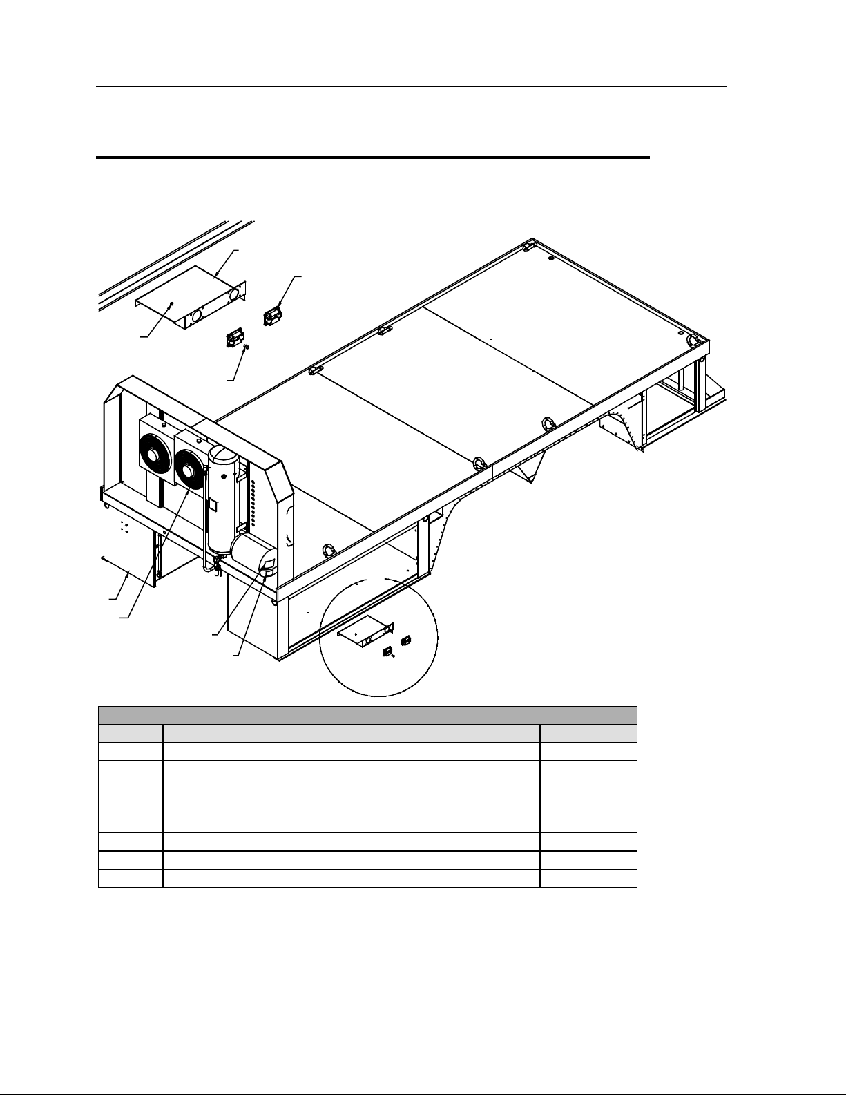
HOSE GUIDE
BRACKET (REF)
1
2
3
VIEW A
4
5
7
6
A
51715800 PARTS LIST
ITEM
PART #
DESCRIPTION
QUANTITY
5.
10001-CMMDR
HYD COMPRESSOR
1 6.
70396127
DECAL
1
7.
301475
DECAL
1
OTR Package Assembly (5171580 0 -1)
1. 70731371 HOSE GUIDE & ROLLER ASM 2
2. 72060004 CAP SCR 1/4-20X1 HHGR5 4
3. 72062104 NUT 1/4-20 LOCK 4
4. 51715799 BODY ASM (SEE DWG) 1
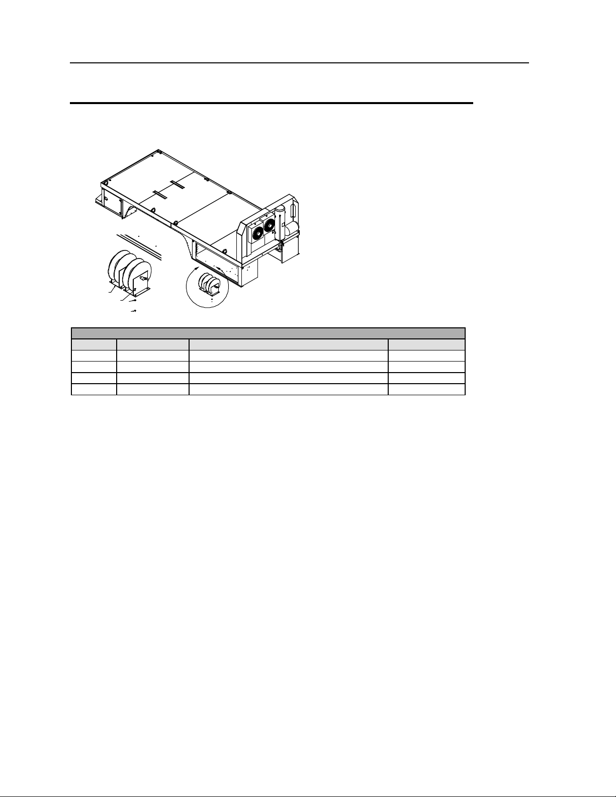
12 14K160TH OTR Body & Air Compressor Manual # 99903184
1
2
4
VIEW B
3
B
51715800-2 PARTS LIST
ITEM
PART #
DESCRIPTION
QUANTITY
1.
70733434
HOSE REEL 1/2X50'
2
2.
72060047
CAP SCR 3/8-16 X 1-1/4 HHGR5
8
3.
72062103
NUT 3/8-16 LOCK
8
4.
76392821
WASHER 3/8 BONDED
8
OTR Package Assembly (5171580 0 -2)
Chapter 2 Parts - OTR Body 13
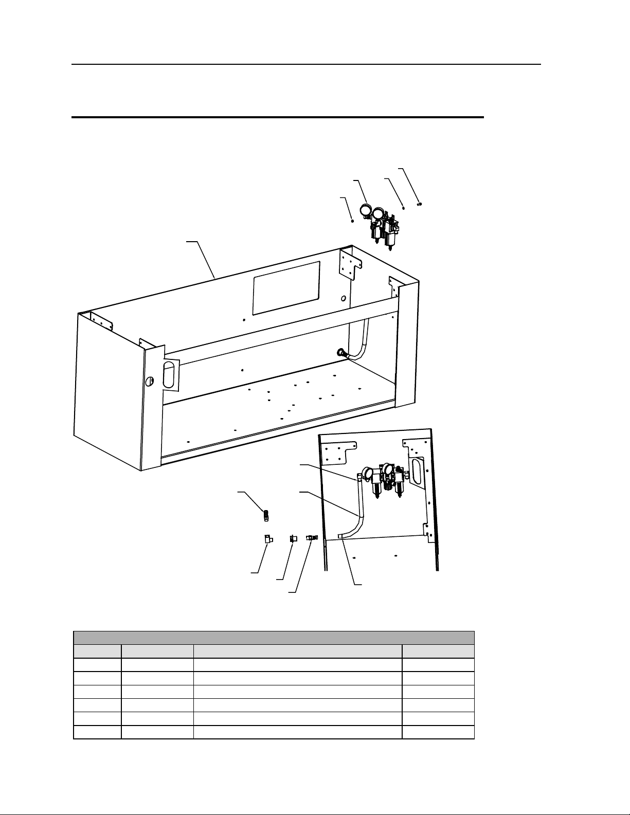
DETAIL VIEW
COMPARTMENT LAYOUT
8
8
97
6
5
7
RIGHT HAND
COMPARTMENT
(REF)
3
1
4
2
51715800-3 PARTS LIST
ITEM
PART #
DESCRIPTION
QUANTITY
1.
51715850
FRL 1 2.
72060004
CAP SCR 1/4-20X1
4
3.
72062104
NUT 1/4-20 LOCK
4
4.
76392820
WASHER 1/4 BONDED
4
5.
72533140
COUPLING 1/2X1-1/2 BULKHD
1
OTR Package Assembly (5171580 0 -3)
6. 72053591 STREET ELBOW 1/2NPT 90° 1

14 14K160TH OTR Body & Air Compressor Manual # 99903184
ITEM
PART #
DESCRIPTION
QUANTITY
7.
72531547
BARB NIPPLE 1/2MPT 3/4HOSE BRS
2
8.
72066000
HOSE CLAMP SAE12
2
9.
89393634
HOSE 100R4 3/4X25
1
FRL (REF)
1
2
1
HOSE
REEL
(REF)
3
1
1
51715800-4 PARTS LIST
ITEM
PART #
DESCRIPTION
QUANTITY
1.
72066000
HOSE CLAMP SAE12
4
2.
89393634
HOSE 100R4 3/4X39
1
3.
89393634
HOSE 100R4 3/4X55
1
51715800-3 PARTS LIST
OTR Package Assembly (5171580 0 -4)
Chapter 2 Parts - OTR Body 15
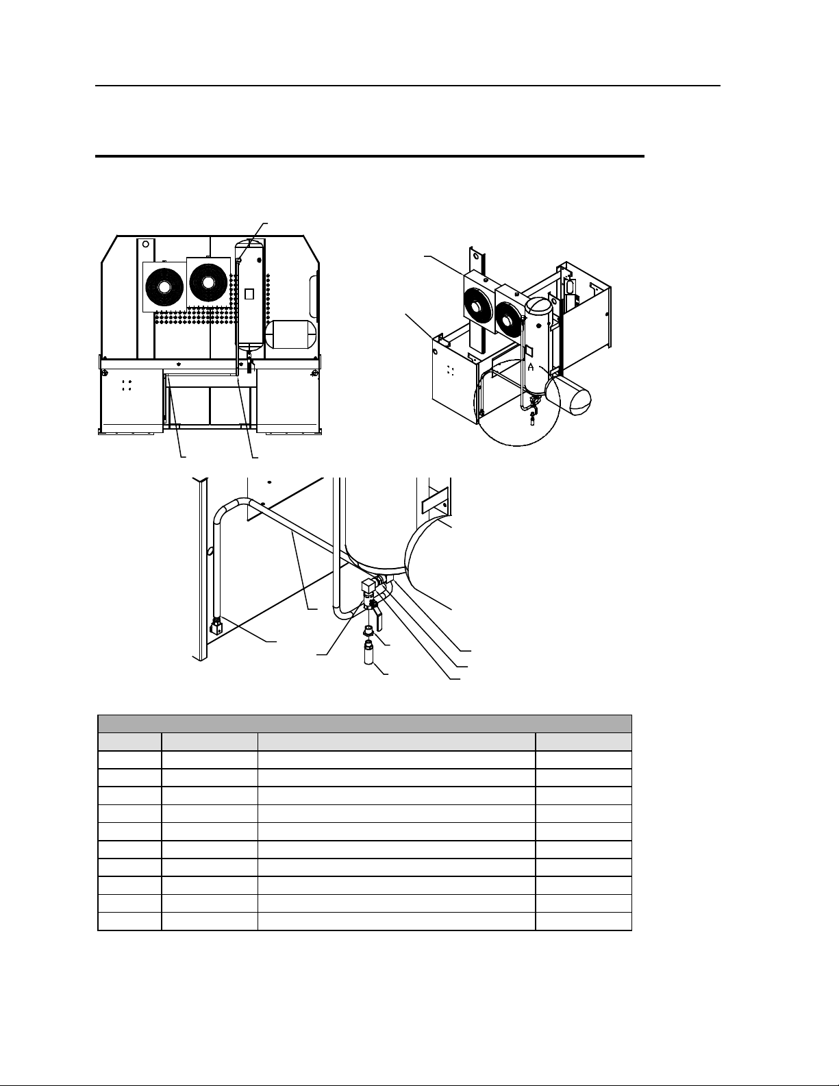
RIGHT HAND
COMPARTMENT
(REF)
COMPRESSOR
(REF)
8,9 8,9
5
6
3
11
10
1
2
1
VIEW A
1,4,5
51715800-5 PARTS LIST
ITEM
PART #
DESCRIPTION
QUANTITY
1.
72053556
STREET ELBOW 3/4NPT 90°
3
2.
72053558
ADAPTER 3/4MPT 3/4MPT HEX
1
3.
73054230
BALL VALVE 3/4NPT
1
4.
72053458
BARB NIPPLE 3/4MPT 3/4HOSE BRS
1
5.
72066000
HOSE CLAMP SAE12
2
10.
70396133
MUFFLER-AIR 3/4 NPT
1
11.
72053375
REDUCER BUSH-BLK 3/4-1/2
1
OTR Package Assembly (5171580 0 -5)
6. 89393634 HOSE 100R4 3/4X120 1
8. 72066533 HOSE CLAMP-VINYL CVR 1/2 2
9. 72060833 SCR 5/16-18X3/4 HWH THRD CTG 2
16 14K160TH OTR Body & Air Compressor Manual # 99903184
A
B
14
13
14
13
14
13
12
14
14
12
11
23
13
14
9
9
8
7
5
8
7
6
7
7
7
6
1
2
4
3,28,
29,30
25,26,
27,35
10,24
DETAIL B
DETAIL A
14(3)
12(3)
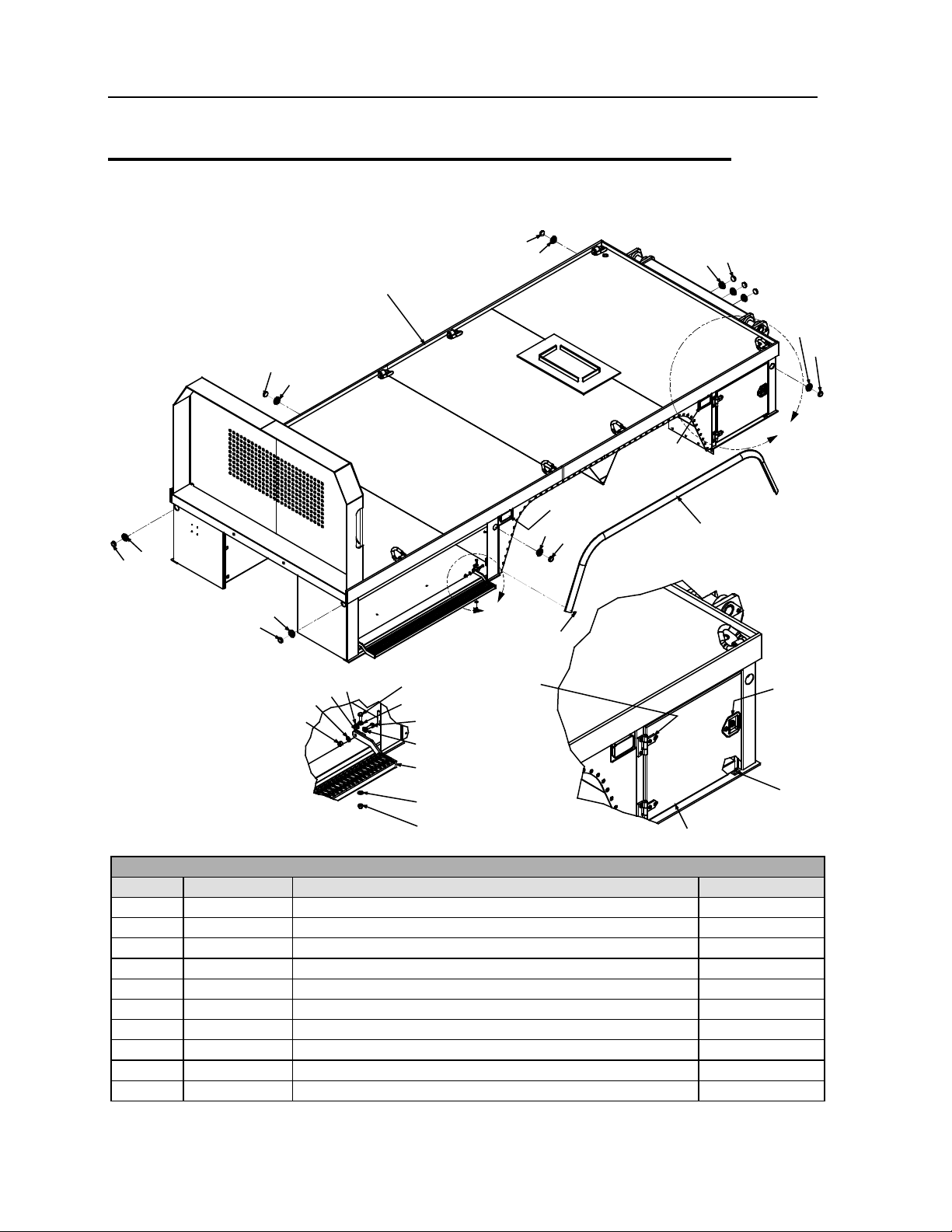
51715799-1 PARTS LIST
ITEM
PART #
DESCRIPTION
QUANTITY
1.
52718265
BODY
1
2.
60122496
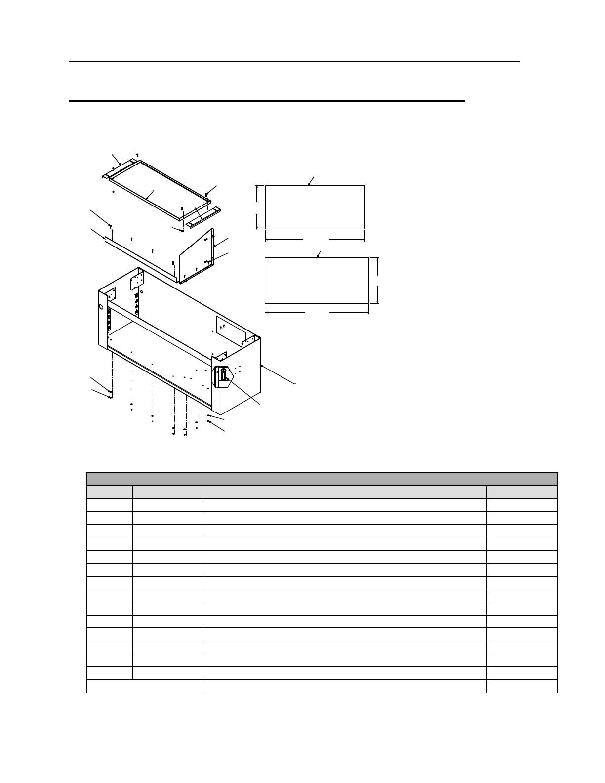
DOOR-WLDMT 24.00H X 27.75W
2
7.
72063005
WASHER .50 FLAT
10
8.
72062080
NUT .50-13 HEX NYLOCK
4
9.
77040404
FLOODLIGHT-COMPOSITE WORK LAMP SIDE MTG
2
10.
72661470
LATCH ASSEMBLY-1PT W/HDW
2
Body Assemb ly (51715799-1)
3. 72661357 HINGE-BUTT 4-NB ZC .50 PIN 4
4. 60122663 BRACKET-HINGE COMMANDER IV STEP 2
5. 52716189 W LDMT-COMMANDER IV STEP 1
6. 72060093 CAP SCREW .50-13X 1.50 HH GR5 Z 4

Chapter 2 Parts - OTR Body 17
51715799-1 PARTS LIST
ITEM
PART #
DESCRIPTION
QUANTITY
14.
76393636
GROMMET-RUBBER 2.00
9
23.
72661384
RIVET-AL LG HD .25X .50 GRIP
96
24.
76393253
GASKET-LATCH W/STUDS
2
25.
60030324
SPACER-1.38 X 1.50 X .62 COMMANDER DOOR
2
26.
72063166
WASHER-SS .25 R WRT 18-8 .62OD
2
27.
72062194
NUT-SS .25-20 NYLOC
2
28.
72601590
CAP SCR-SS .31-18X1.00 TRH PHH
16
11. 89393137 FENDER RUBBER 2
12. 77040543 LIGHT-CLEAR RED LED (77040357 THRU 4-09) 5
13. 77040478 LIGHT-CLEAR AMBER LED (77040358 THRU 4-09) 4
29. 72063002 WASHER .31 FLAT 16
30. 72062167 NUT-SS .31-18 HEX NYLOC 16
35. 72601593 SCR-MACH .25-20X 1.50 FLH SS 2
REV. L 20090423
18 14K160TH OTR Body & Air Compressor Manual # 99903184
36
36
40
38
20
21
37
41
39
22
42
96"
85.63"
33.88"
51.75"
82.86"
43 (BOTH SIDES)
(BOTH
SIDES)
40
(BOTH
SIDES)
38
56.81" 58.69"
35.65"
15,17
15,17
15,17
15,17
15,16
15,16
36
(BOTH
SIDES)
233.25"
242"
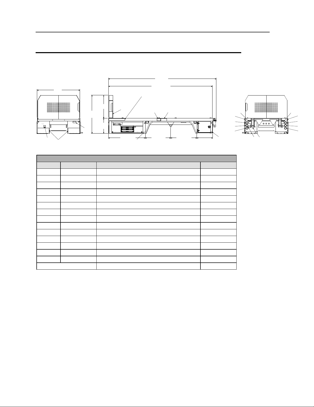
51715799-2 PARTS LIST
ITEM
PART #
DESCRIPTION
QUANTITY
15.
76392275
GROMMET-TAIL LIGHT
6
16.
77040180
LIGHT-BACKUP
2
36.
70039057
REFLECTOR-RED RD
4
37.
70039058
REFLECTOR-AMBER RD
2
38.
70392865
DECAL-DANGER ELEC HAZARD(LARGE
3
39.
71393886
DECAL-DANGER EXPLODING TANK
1
40.
70392868
DECAL-DANGER CR LOADLINE (TRK)
3
41.
70395701
PLACARD-MAX LIFT 14K160TH
1
42.
70392891
DECAL-DANGER DRIVELINE
1
Body Assemb ly (51715799-2)
17. 77040493 LIGHT-STOP/TURN/TAIL LED 4" 4
20. 77040006 LIGHT-LICENSE PLATE 2
21. 51715985 KIT-LICENSE PLATE HARDWARE 1
22. 60350058 TREAD-SHUR STEP 12in X 26in 2
43. 70395823 DECAL-IDENT COMMANDER IV 3
REV. K 20090102
Chapter 2 Parts - OTR Body 19
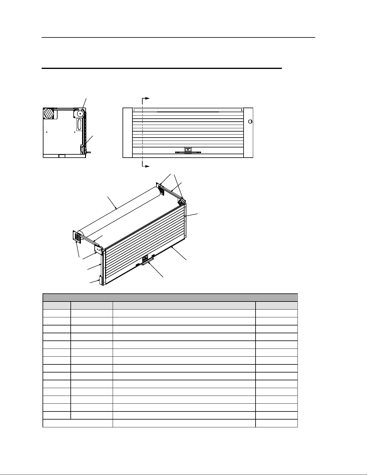
SECTION F-F
F
F
76
77
78
79
80
81
83
85
86
85
82,84
35,40,75
51715799-3 PARTS LIST
ITEM
PART #
DESCRIPTION
QUANTITY
35.
72601593
SCR-MACH .25-20X 1.50 FLH SS
6
40.
72062104
NUT .25-20 HEX NYLOCK
14
75.
72661269
HANDLE-GRAB CHROME 16L 3H 819
1
78.
71413564
PLATE - LH HEAD ASM
1
79.
71413565
COUNTER BALANCE ROLLER
1
80.
71413566
81.
71413567
SEAL - DOOR SIDE
2
82.
71413568
LATCH CATCH
2
83.
71413569
ANGLE - 2 X 1 X .12 X 6
2
84.
71413570
STUD .31-16 X .62
4
Body Assemb ly (51715799-3)
76. 71413562 WHEEL-.50 X 4.00 NYLON 1
77. 71413563 PLATE - RH HEAD ASM 1
TRACK - VERT (ORDER SET - INCLUDES RH & LH) 1
85. 71413571 TRACK-HORIZONTAL 2
86. 71413572 DOOR-ROLL UP 22.00 H X 70.00 W REPLACEMENT 1
REV. K 20090304

20 14K160TH OTR Body & Air Compressor Manual # 99903184
ROLL-UP DOOR PROCEDURE:
1 CLAMP VERTICAL RAILS (#80) INTO PLACE. DO NOT INSTALL AT THIS TIME.
2 INSTALL DOOR HEADER. CENTER BETWEEN VERTICAL JAMS.
3 UNCLAMP VERTICAL RAILS (#80 AND PLACE OFF TO SIDE.
4 INSTALL COUNTERBALANCE ROLLER BRACKETS.
5 INSTALL HORIZONTAL RAILS (#85).
6 INSTALL COUNTERBALANCE ROLLER (#79). PAY CLOSE ATTENTION TO TO THE WRAP DIRECTION
DECAL.
7 UNROLL SLATS ON ROLL-UP DOOR (#86) WHILE FEEDING IT INTO THE RADIUS CORNER
COMPONENTS.
8 INSTALL THE THREE SHUTTER STRAPS ONTO THE COUNTERBALANCE ROLLER. INSTALL ONE STRAP
IN THE MIDDLE OF THE COUNTERBALANCE ROLLER. INSTALL THE OTHER TWO STRAPS THREE
INCHES FROM EACH END.
9 PULL NAIL ON THE COUNTERBALANCE ROLLER. THIS WILL CREATE TENSION TO HELP THE DOOR
ROLL UP.
10 INSTALL THE VERTICAL RAILS (#80). LEAVE DOOR DOWN A FEW INCHES AND ANGLE DOOR BACK
ENOUGH TO ALLOW VERTICAL RAILS (#80) TO SLIDE INTO PLACE.
11 INSTALL FLIPPER CATCHES (#82). THE RUBBER ON THE BOTTOM OF THE DOOR MUST BE
COMPLETELY FLAT WHEN THE DOOR IS SHUT.
12 INSTALL THE HANDLE (#75). DRILL HOLES IN DOOR FOR INSTALLATION.
13 ADJUST THE CABLE LENGTH WITH THE TURN BUCKLE. MAKE SURE THE CABLE IS JUST TIGHT
ENOUGH TO ALLOW PADDLE HANDLE LOCKS TO COMPLETELY OPEN. TIGHTEN DOUBLE NUTS.
14 INSTALL ALUMINUM PROTECTIVE COVER. USE COVER AS A TEMPLATE TO DRILL HOLES. USE #7 CAP
SCREWS AND #5 NYLOC NUTS.
15 APPLY DOOR LUBRICANT. MAKE SURE ALL DEBRIS IS OUT OF DOOR RAILS AND RUBBER SEALS
BEFORE APPLYING LUBRICANT.
16 APPLY WHITE PERFLEX SEALANT BETWEEN COMPARTMENT AND ROLL-UP DOOR.
Chapter 2 Parts - OTR Body 21
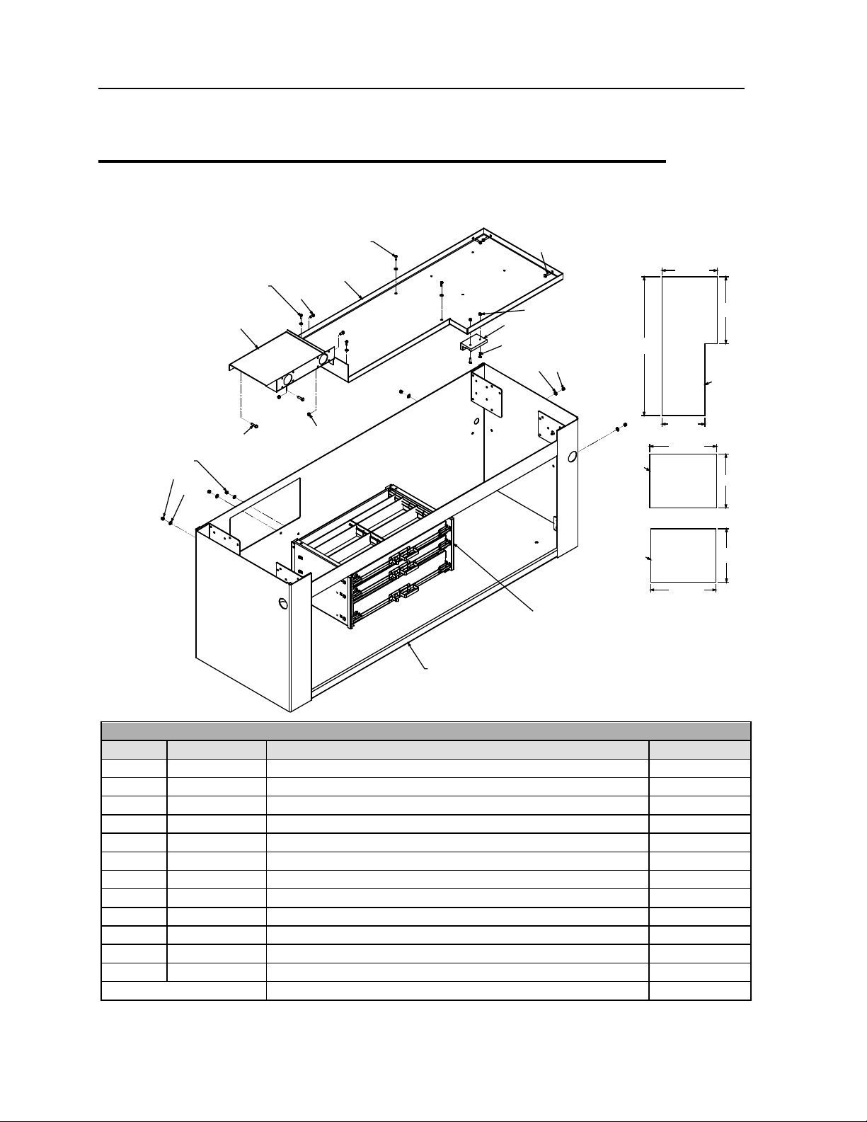
32
33
34
31
52
63
63
EXISTING HARDWARE
FROM DRAWER SET
EXISTING HARDWARE
FROM DRAWER SET
EXISTING HARDWARE
FROM DRAWER SET
38(2)
62(2)
36(2)
38(2)
51(2)
36(4)
40(2)
50(2)
62(2)
38(2)
RIGHT HAND COMPARTMENT
(REF)
22.25"
55.75"
17.25"
26.75"
26.75"
26.25"
21.5"
21.5"
51715799-4 PARTS LIST
ITEM
PART #
DESCRIPTION
QUANTITY
31.
70733807
DRAWERS PAINTED 26W 2-3in/1-5in 42.62X17.5
1
32.
52716191
WELDMENT-SHELF FRONT LH COMPT COMMANDER IV
1
33.
52716192
WELDMENT-SHELF FRONT LH COMPT COMMANDER IV
1
50.
72060004
CAP SCREW .25-20X 1.00 HH GR5 Z
2
51.
72060023
CAP SCREW .31-18X .75 HH GR5 Z
2
52.
76395950
MAT-RUBBER .08" THK 2'W
3.9 FT
62.
76392598
WASHER-BONDED PLTD .31
11
63.
76393340
MAT-RUBBER .38X 24.00
6 FT
REV. K 20090105
Body Assemb ly (51715799-4)
34. 60030316 STOP-UHMW COMMANDER 4 STEP 1
36. 72060026 CAP SCREW .31-18X 1.25 HH GR5 Z 11
38. 72062109 NUT .31-18 HEX NYLOCK 13
40. 72062104 NUT .25-20 HEX NYLOCK 10
22 14K160TH OTR Body & Air Compressor Manual # 99903184
56
55
57
54
53
63
52
RIGHT HAND
COMPARTMENT
(REF)
18,19
38(5)
62(5)
21.5"
20.75"
47.25"
49.25"
40(4)
61(4)
60(4)
58(4)
36(5)
59(4)
51715799-5 PARTS LIST
52.
76395950
MAT-RUBBER
3.9 FT
53.
60122686
ANGLE-DOOR PROTECTOR COMMANDER IV
1
54.
52716198
DIVIDER-SHELF UNDER-BODY TOOLBOX W/HANGER BRACKET
1
55.
60122685
SHELF-21.00X 47.50 (ADJ SHELF)
1
56.
60110252
END-ADJ SHELF RH 21.00
1
57.
60110251
END-ADJ SHELF LH 21.00
1
58.
72060046
CAP SCR .38-16X 1.00 HH GR5 Z
4
62.
76392598
WASHER-BONDED PLTD .31
11
63.
76393340
MAT-RUBBER .38X 24.00
6 FT
REV. K 20090105
Body Assemb ly (51715799-5)
NOTE:
1 INSTALL ITEM #63 INSIDE BOTTOM OF COMPARTMENT.
ITEM PART # DESCRIPTION QUANTITY
18. 76394572 GROMMET-2 X 6 OVAL CMPT LIGHT 6
19. 77040384 LIGHT-COMPARTMENT 12V 2.1AMP 6
59. 72062103 NUT .38-16 HEX NYLOCK 4
60. 72060005 CAP SCR .25-20X 1.25 HH GR5 Z 4
61. 76392820 WASHER-BONDED PLTD .25 4
Chapter 2 Parts - OTR Body 23
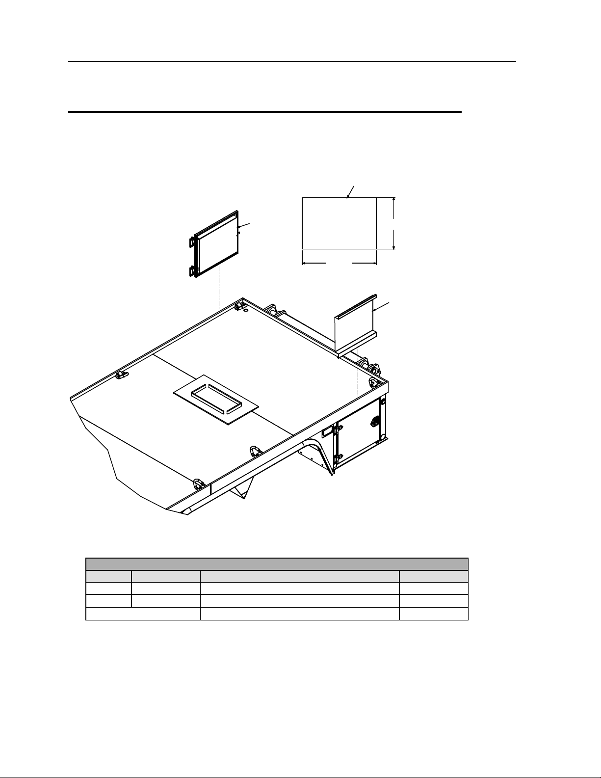
RUBBER MAT
51715799-6 PARTS LIST
ITEM
PART #
DESCRIPTION
QUANTITY
63.
76393340
MAT-RUBBER .38X 24.00
6 FT
Body Assemb ly (51715799-6)
CUT DIMENSIONS
63(2)
64
24"
34.5"
64
NOTE:
1 INSTALL ITEM #4 INSIDE BOTTOM OF COMPARTMENT. MAKE SURE TO BUTT FACTORY EDGES
TOGETHER.
64. 60122684 PANEL-DOOR LINER (SIDE) COMMANDER IV 2
REV. K 20090105
 Loading...