

ISL-54
SERIES D
EMERGENCY
P.O. BOX 11846 TUCSON, AZ 85734
(520) 294-3292 • FAX (520) 741-2837
www.iotaengineering.com
INSTRUCTION MANUAL
IMPORTANT SAFEGUARDS
When using electrical equipment, basic safety precautions should always be followed, including the following:
READ AND FOLLOW ALL SAFETY INSTRUCTIONS
1. CAUTION – To prevent electrical shock, do not mate unit connector until installation is complete and A.C. power
is supplied to the unit.
2. CAUTION – This fixture provides more than one power supply output source. To reduce the risk of electrical
shock, disconnect both normal and emergency sources by turning off the A.C. branch circuit and by disconnecting the unit connector.
3. CAUTION – This is a sealed unit. The integral, high temperature Ni-Cad battery is not replaceable. Replace the
entire unit when necessary and recycle or dispose of the nickel-cadmium battery properly.
LIGHTING EQUIPMENT
4. DO NOT USE OUTDOORS. The ISL-54 is for use with grounded, UL Listed, damp location rated, indoor fixtures.
Not for use in heated air outlets or hazardous locations.
5. The ISL-54 requires an unswitched A.C. power source of either 120 or 277 volts. Properly cap the unused A.C.
lead.
6. Do not mount near gas or electric heaters.
7. The ISL-54 should be mounted in locations and at heights where it will not readily be subjected to tampering by
unauthorized personnel.
8. The ISL-54 will cold strike and operate for 90 minutes one 2′ to 4′ T5, 17W to 30W T6, or 17W to 40W T8 linear
lamp, including HO and 4 pin long compact fluorescent lamps, from 36 through 55 watts.
9. The ISL-54 is compatible with all A.C. magnetic and electronic ballasts including multiple lamp ballasts with one
lamp operating in the emergency mode.
10. Suitable for use in damp locations.
11. For use in 0° C minimum, 50° C maximum ambient temperatures.
12. The use of accessory equipment not recommended by the manufacturer may cause an unsafe condition.
13. Do not use this equipment for other than intended use.
14. Install in accordance with the National Electrical Code and local regulations.
15. Installation and servicing should be performed by qualified personnel.
16. Lighting fixture manufacturers, electricians, and end-users need to ensure product system compatibility before
final installation.
SAVE THESE INSTRUCTIONS
INSTALLATION INSTRUCTIONS
CAUTION: Before installing, make certain the A.C. power is off and the
ISL-54 unit connector is disconnected.
1. MOUNTING THE ISL-54
Remove the ballast channel cover. Mount the ISL-54 in the ballast channel at least 1/2″ away from the A.C.
ballast(s).
When battery packs are remote mounted, consult Customer Service for the maximum allowable distance between
the battery pack and the lamp.
2. WIRING
Refer to the wiring diagrams on the back page for the appropriate wiring of lamp(s) and ballast. Install in accordance
with the National Electrical Code and local regulations. For additional wiring diagrams consult Customer Service.
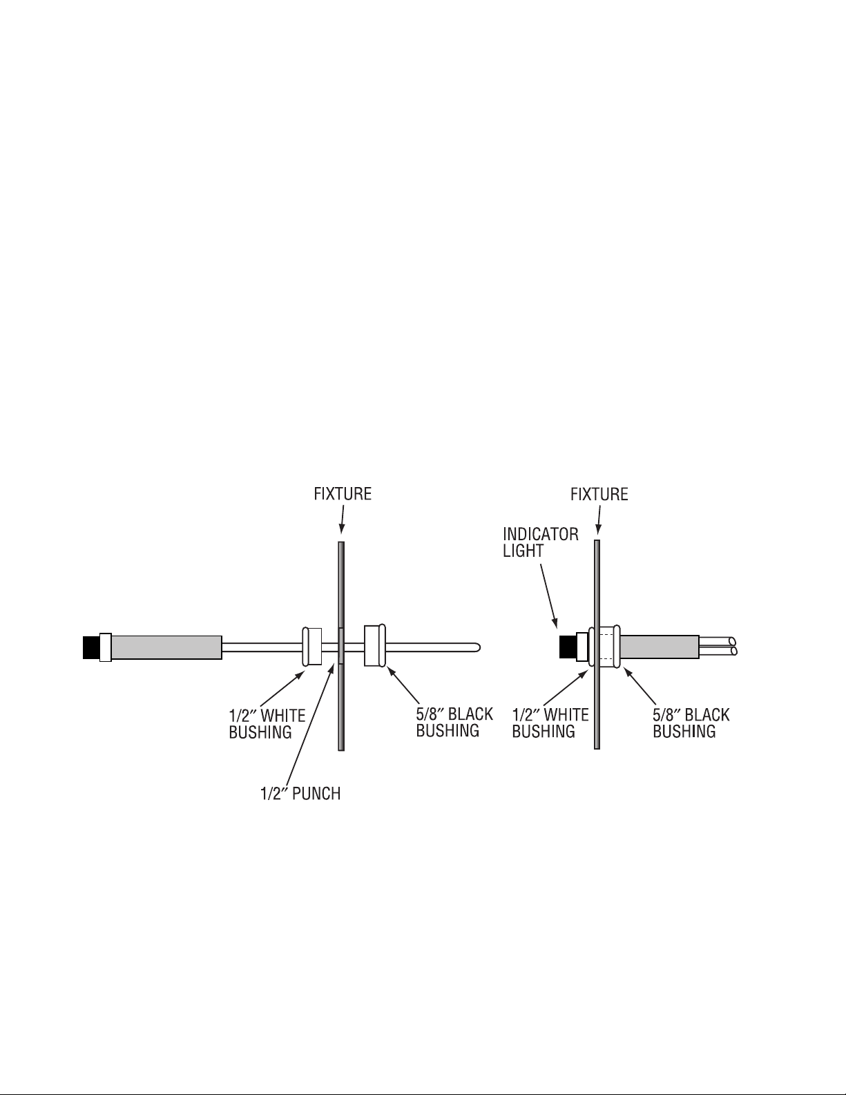
3. INSTALLING THE CHARGE INDICATOR
Select a convenient location on the side of the fixture so the Charge Indicator can be seen after installation.
Allow for proper clearance inside the fixture and drill or punch a ½″ hole. Snap the ½″ white bushing into the hole.
Push the LED housing into the bushing and secure it in place with a 5/8″ black bushing (see Illustration 1).
Connect the LED red and white wires to the ballast LED marked wires.
Illustration 1
4. INSTALLING THE TEST SWITCH
The Test Switch should be mounted on the side of the fixture, preferably adjacent to the charge indicator. Drill or
punch a ½″ mounting hole.
5. WIRING THE A.C. INPUT
A. The ISL-54 and A.C. ballast must be on the same branch circuit.
B. The ISL-54 requires an unswitched A.C. power source of either 120 or 277 volts. Select the proper voltage
lead and cap the unused lead.
C. When the ISL-54 is used with a switched fixture, the A.C. input to the ISL-54 must be connected ahead of the
fixture switch. Refer to Illustration 2 for switched and unswitched fixture wiring diagrams.
Page 2
 Loading...