


ISD-80
SERIES AC
UNIVERSAL VOLTAGE
EMERGENCY
P.O. BOX 11846 TUCSON, AZ 85734
(520) 294-3292 • FAX (520) 741-2837
www.iotaengineering.com
INSTRUCTION MANUAL
IMPORTANT SAFEGUARDS
When using electrical equipment, basic safety precautions should always be followed, including the following:
READ AND FOLLOW ALL SAFETY INSTRUCTIONS
1. CAUTION – To prevent electrical shock, do not mate unit connector until installation is complete and A.C. power
is supplied to the unit.
2. CAUTION – This fixture provides more than one power supply output source. To reduce the risk of electrical
shock, disconnect both normal and emergency sources by turning off the A.C. branch circuit and by disconnect
ing the unit connector.
3. CAUTION – This is a sealed unit. The integral, high temperature Ni-Cad battery is not replaceable. Replace the
entire unit when necessary and recycle or dispose of the nickel-cadmium battery properly.
4. DO NOT USE OUTDOORS. The ISD-80 is for use with grounded, UL Listed, damp location rated, indoor fix
tures. Not for use in heated air outlets or hazardous locations.
5. The ISD-80 requires an unswitched A.C. power source of 110-277V 50/60Hz.
6. Do not mount near gas or electric heaters.
7. The ISD-80 should be mounted in locations and at heights where it will not readily be subjected to tampering by
unauthorized personnel.
8. The ISD-80 is suitable for mounting in the ballast compartment or on top of the fixture. For top mount, order
optional mounting kit TMK-80.
9. The ISD-80 will cold strike and operate one 14W to 54W T5 or 2′–4′ instant start, rapid start, U shape or circline,
T8 through T12 fluorescent lamps, including energy saving and 4-pin long compact lamps for 90 minutes.
Not for use with single-pin lamps.
10. The ISD-80 is compatible with most A.C. ballasts (including multiple lamp) as follows:
Magnetic ballasts – one lamp emergency operation.
Electronic ballasts – one lamp emergency operation.
11.
ATTENTION - The ISD-80 utilizes filament heaters and an AC output circuit for wider compatibility of lamp types,
therefore rapid start sockets only must be used for the emergency lamp application. The emergency lamp pins
must be wired independently to avoid shorting on the output circuit. Instant start sockets should not be used.
12. Suitable for use in damp locations and in enclosed and gasketed fixtures.
13. When used in conjunction with enclosed and gasketed fixtures, the ISD-80 is suitable for mounting in the ballast compartment only.
For use in 0° C minimum, 50° C maximum ambient temperatures.
14.
15. The use of accessory equipment not recommended by the manufacturer may cause an unsafe condition, void
warranty, and result in non-compliance with UL specifications
16. Do not use this equipment for other than intended use.
17. Install in accordance with the National Electrical Code and local regulations.
18. Installation and servicing should be performed by qualified personnel.
19. Lighting fixture manufacturers, electricians and end users need to ensure product system compatibility before
final installation.
.
LIGHTING EQUIPMENT
-
-
SAVE THESE INSTRUCTIONS
FIXTURE
LPTS
+ RED
LEAD
WHITE/RED
LEAD
+ RED
7/8" BUSHING
FIXTURE
BALLAST CHANNEL COVER
PLASTIC TUBE
LPTS
FIXTURE LENS
INSTALLATION INSTRUCTIONS
CAUTION: Before installing, make certain the A.C. power is off and the ISD-80 unit connector is disconnected.
1. LAMPS OPERATED
The ISD-80 can be used with most 2′–4′ lamps 2-pin lamps. The ISD-80 is not for use with single-pin lamps. Refer
to the chart below for the type of lamp to be operated in emergency mode.
OPTION
1
2
3
4
5
6 18W-36W Long Compact One Lamp Connected
7
LAMP TYPE
2´-4´ T8/T12 Bipin
2´-4´ 14W-24W T5
2´-4´ 28W-54W T5
22W T9, 9W T5 Circline
12W, 55W T5 Circline
40W-55W Long Compact
EMERGENCY
OPERATION
One Lamp
One Lamp
One Lamp
One Lamp
One Lamp
One Lamp
*The 6″ violet leads provide the lamp selection option. The unit is shipped from the factory with the leads
disconnected and capped. When used with particular lamp types, violet leads should be connected to one another. Refer to chart for lamp selection options.
2. MOUNTING THE ISD-80
Remove the ballast channel cover. Mount the ISD-80 in the ballast channel at least ½″ away from the A.C. ballast.
The ISD-80 may also be mounted on top of the fixture. The optional top mounting kit (Catalog No. TMK-80) may
be ordered separately from Customer Service.
When battery packs are remote mounted, consult Customer Service for the maximum allowable distance between
the battery pack and the lamp.
*VIOLET LEADS
Connected
Connected
Disconnected
Connected
Disconnected
Disconnected
3. WIRING
Refer to the wiring diagrams on the back page for the appropriate wiring of lamp(s) and ballast. Install in accordance
with the National Electrical Code and local regulations. For additional wiring diagrams consult Customer Service.
ATTENTION - The ISD-80 utilizes filament heaters and an AC output circuit for wider compatibility of lamp types,
therefore rapid start sockets only must be used for the emergency lamp application. The emergency lamp pins
must be wired independently to avoid shorting on the output circuit. Instant start sockets should not be used.
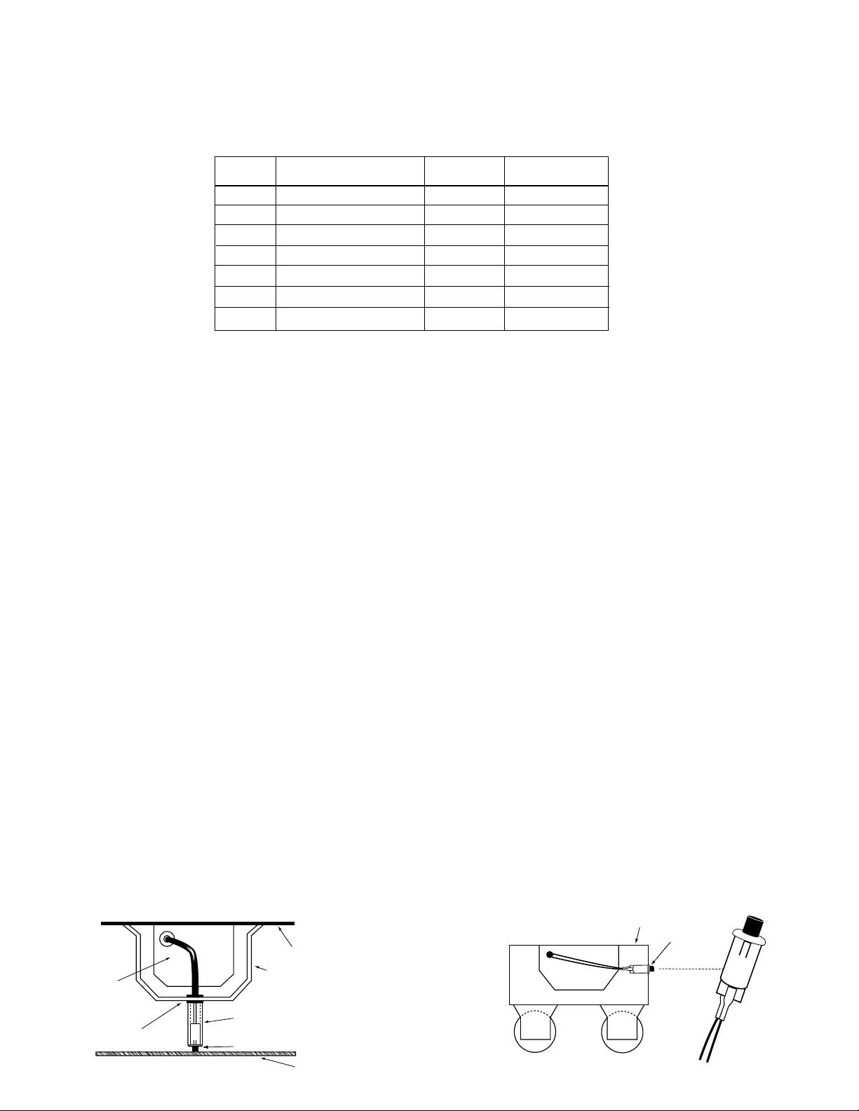
4. INSTALLING THE LIGHTED PUSH BUTTON TEST SWITCH (LPTS)
Recessed Troffer Fixture – Select a convenient location with proper clearance in the ballast cover and drill or
punch a 7/8″ hole (½″ knockout). Insert the 7/8″ bushing into the hole. Push the plastic tube through the bushing.
Disconnect the leads from the LPTS housing and route the leads down the plastic tube. Reconnect the leads to
the housing, observing the proper polarity (Red/Black or Red lead w/connector to positive (+) tab. The positive
terminal will be indicated by the red mark on the side of the LPTS switch). Push the entire assembly back into the
tube until the lens collar rests against the plastic tube. The plastic tube should be adjusted so that the LPTS is within
¼″ of the fixture lens. The LPTS must be visible after installation. Refer to Illustration 1.
Strip Fixture – Select a convenient location on the side of the fixture so the LPTS can be seen after installa-
tion. Allow for proper clearance inside the fixture and drill or punch a ½″ hole. Disconnect the leads from the LPTS
housing. Push the LPTS housing into the ½″ hole until it is firmly locked in place. Reconnect the leads, observing
the proper polarity (Red/Black or Red lead w/connector to positive (+) tab. The positive terminal will be indicated
by the red mark on the side of the LPTS switch). Refer to Illustration 2.
NOTE: For proper operation, use only the test accessories provided with the unit. See Page 1 of the Instruction
Manual.
Illustration 1 Recessed Troffer Fixture Illustration 2 Strip Fixture
ISD-80
Page 2
ISD-80
OBSERVE PROPER POLARITY
POS
(POS LEAD)
RED/BLK
OR RED
W/CONNECTOR
 Loading...