

P.O. BOX 11846 TUCSON, AZ 85734
(520) 294-3292 • FAX (520) 741-2837
www.iotaengineering.com
IQ4 CHARGE CONTROLLER FOR DLS
OWNER’S MANUAL
The IQ4 Charge Controller offers automatic charging control for DLS
Battery Chargers, providing longer and safer use of your system’s
battery. The IQ4 Controller allows the DLS Charger to operate as an
automatic 3-stage “smart charger” that gives the customer the benefit
of Bulk, Absorption, and Float stage charging. Three-Stage Charging
increases the charging capacity of the DLS charger and decreases
the charge time while insuring proper and safe battery charging and
minimizing the possibility of over-charging. The IQ4 monitors the battery at all times. If the DLS voltage remains in the Float stage for more
than seven days, the IQ4 will automatically enter the Equalization stage
for a predetermined time to help maintain the battery plates, and then
resume float stage charging.
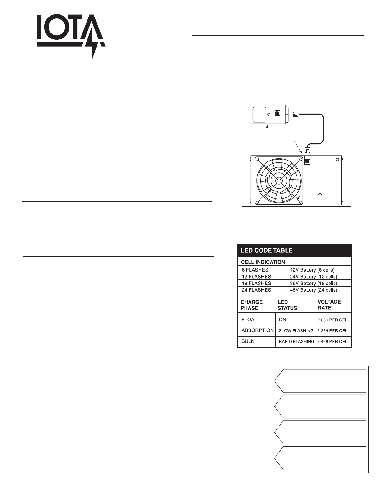
INSTALLATION OF THE EXTERNAL IQ4
The IQ4 Charge Controller installs by simply plugging the IQ4 cord
into the Dual Voltage jack located on the DLS* (Refer to Figure A).
The IQ4 circuitry is then automatically engaged. Note: the cord pro-
vided is specifically designed for use with the IQ4. Do not use the IQ4
with any cord other than one supplied with the unit.
LED INDICATOR
The LED Indicator on the IQ4 informs the user of the DLS charging
state and the battery charge status. When first activated, the IQ4 will
read the number of cells in the battery and indicate the voltage of the
battery through a number of flashes. Refer to Figure B.
FIGURE A. IQ4 INSTALLATION
IQ CHARGE CONTROLLER
DUAL VOLTAGE JACK
*Location of the Dual Voltage Jack may vary depending on the DLS Model.
FIGURE B. LED INDICATOR CHART
LIT/FLASHING LED - After reading the battery, the IQ4 will initiate
either a Bulk Charge phase or Float Charge phase depending on the
battery’s charge status. When the IQ4 is in the Bulk Charge mode, the
green LED indicator will flash rapidly (approx. 2 flashes per second).
When the Bulk Charge is complete, the IQ4 begins the Absorption
Charge and the LED indicator will flash at a slower rate (approx. 1
flash per second). If, when first activated, the battery is not in need of
charging, the IQ4 will immediately begin the Float Charge phase and
the LED will be remain lit (no flashing). Refer to Figure C for Charge
Stage descriptions.
The LED indicator will remain lit or flashing when the charger is unplugged or disconnected from the AC supply (de-energized). During
this time, the IQ4 continues to monitor the battery voltage. If the battery voltage drops below a pre-determined voltage (Refer to Figure
D for predetermined values), the IQ4 will automatically initiate the
3-Stage Charge (BULK, ABSORPTION, and FLOAT) once the AC input is re-connected.
IRREGULAR FLASHING LED - If the LED is flashing irregularly or
intermittently, then the IQ4 has entered a FAULT state due to an overvoltage. When this occurs, the IQ4 must be re-set in order to resume
normal operation. Refer to the FAULT STATE instructions on page 2
for re-setting procedures.
FIGURE C. CHARGING STATE FUNCTIONS
The Bulk State charges the battery at the
BULK
ABSORPTION
FLOAT
EQUALIZATION
full-rated output of the charger, reducing
the time it takes to charge the battery.
The Absorption State delivers a constant
charge for a set period of time to ensure that
the battery receives a full and complete charge.
Once the battery has been fully charged, the
Float State maintains a full charge to the battery
while minimizing “gassing.”
If the battery has remained in the Float State for
seven days, the IQ4 automatically provides an
equalization charge to dissolve any sulfate layer
on the battery’s plates and to avoid stratification.

OPERATION OF THE IQ4 IN THE 3-STATE MODE
BULK STAGE - During this state, the charger will operate either at Full Current output or Constant Voltage output depending on the discharged state of the battery. A discharged battery will dictate the voltage and force the charger into constantcurrent operation. As the battery charges, the charger transitions to a constant-voltage operation. This BULK STAGE will
continue for either 225 minutes or until the battery voltage reaches the “High Trigger” value (whichever occurs first). At this
point, the BULK STAGE will operate for another 15 minutes before switching to the ABSORPTION STAGE.
ABSORPTION STAGE - This state is limited to 480 minutes (8 hours) during which the charger will operate either at Full
Current output or Constant Voltage output depending on the discharged state of the battery. During Full Current output, the
charger is providing its full current rating and will slowly increase the battery voltage to the “Absorption Stage” voltage. At the
end of the 480 minutes, the charger will revert to the FLOAT STAGE.
FLOAT STAGE - This charge state holds the batteries at Constant Voltage for a period not longer than seven days. During
this state, the charger not only floats the batteries, but it can also provide load current up its maximum rating for other loads
without depleting the battery capacity. The FLOAT STAGE will end when either the battery voltage drops below the “Low Trigger” point or at the end of seven days when the IQ4 initiates an equalization stage to remove sulfate layers from the battery
plates. In either situation, the unit exits the FLOAT STAGE and enters the BULK STAGE.
FAULT STATE - If the IQ4 is exposed to an “over voltage” condition by exceeding the “Over Voltage Trigger,” its circuitry is
automatically disabled. In this state, the functionality of the IQ4 is completely disabled, the LED will flash irregularly, and the
charger reverts to a stand-alone FLOAT STATE voltage. The unit will not exit this stand-alone FLOAT STATE, therefore the
unit must be reset by following the steps below.
1. Unplug the charger from its AC source.
2. Disconnect the [+] positive cable from the battery.
3. Wait 30 seconds before reconnecting the input and output. To avoid arcing, it is recommended that the charger be
connected to the AC input FIRST before connecting the output of the charger to the battery*.
*Note that the connection sequence of the input and output covered above is recommended every time an operator connects the charger to the batteries.
However, as long as the charger remains connected to the battery, periodic unplugging of the AC input does not require this sequence
FIGURE D. OPERATING VARIABLES
PREDETERMINED VARIABLES FOR OPERATION
Battery
Voltage
12V
24V
36V
48V**
**48V applications require the IQ4-54V Model
BULK
14.8V
29.6V
44.3V
59.2V
ABSORPTION
14.2V
28.4V
42.6V
56.8V
FLOAT
13.6V
27.2V
40.7V
54.4V
LOW
TRIGGER
12.8V
25.6V
38.4V
51.2V
HIGH
TRIGGER
14.6V
29.2V
43.8V
58.4V
OVER VOLTAGE
FAULT
15.2V
30.4V
45.6V
60.8V
 Loading...