


ILB
‘A’ MOUNTING DESIGN
EMERGENCY
LIGHTING EQUIPMENT
P.O. BOX 11846 TUCSON, AZ 85734
(520) 294-3292 • FAX (520) 741-2837
www.iotaengineering.com
INSTRUCTION MANUAL
IMPORTANT SAFEGUARDS
When using electrical equipment, basic safety precautions should always be followed, including the following:
READ AND FOLLOW ALL SAFETY INSTRUCTIONS
1. CAUTION – To prevent electrical shock, do not mate unit connector until installation is complete and A.C.
power is supplied to the unit.
2. CAUTION – This fixture provides more than one power supply output source. To reduce the risk of electrical
shock, disconnect both normal and emergency sources by turning off the A.C. branch circuit and by discon-
necting the unit connector.
FOR LED
3. CAUTION – This is a sealed unit. Components are not replaceable. Replace the entire unit when necessary.
4. CAUTION – Installation and servicing should be performed by qualified personnel only. De-energize before
opening.
5. DO NOT USE OUTDOORS. The ILB is for use with grounded, UL Listed, damp location rated, indoor fixtures.
Not for use in heated air outlets or hazardous locations.
6. The ILB requires an unswitched A.C. power source of either 120 or 277 volts. Properly cap the unused A.C.
lead.
7. The ILB and A.C. driver must be on the same branch circuit.
8. Do not mount near gas or electric heaters.
9. The ILB should be mounted in locations and at heights where it will not readily be subjected to tampering by
unauthorized personnel.
10. The ILB will supply 24VDC or 12VDC output at the individual rated specification for 90 minutes. See individual
units for output specifications.
11. Suitable for use in damp locations.
12. For use in 0° C minimum, 50° C maximum ambient temperatures.
13. The use of accessory equipment not recommended by the manufacturer may cause an unsafe condition.
14. Do not use this equipment for other than intended use.
15. Install in accordance with the National Electrical Code and local regulations.
16. Lighting fixture manufacturers, electricians, and end-users need to ensure product system compatibility before
final installation.
SAVE THESE INSTRUCTIONS
INSTALLATION INSTRUCTIONS
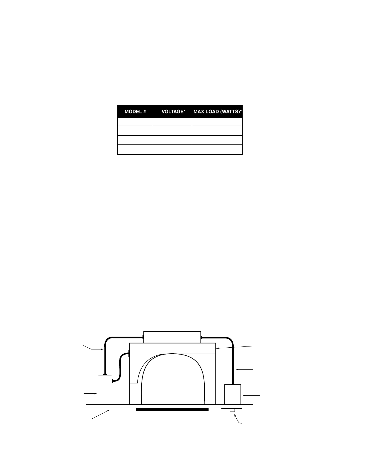
FLEX “A”
JUNCTION
BOX
CEILING
TILE
A.C. BALLAST &
LAMP SOCKET COMPARTMENT
FLEX “B”
SWITCH BOX
TEST SWITCH
CHARGE LIGHT
ILB MODEL SPECIFICATION CHART
CAUTION: Before installing, make certain the A.C. power is off and the ILB unit
connector is disconnected.
1. LED LIGHT
The ILB can be used with most LED loads that operate at 24VDC or 12VDC. See ILB Model
Specification Chart for output specifications of the unit being installed.
ILB-1207
ILB-1212
ILB-2407
ILB-2412
*ALL VOLTAGES AND WATTAGES ARE NOMINAL
12VDC
12VDC
24VDC
24VDC
7
12
7
12
2. MOUNTING THE ILB
The ILB should be mounted on or nearby the fixture above the ceiling. The flex conduit marked “A” should be
wired into the driver/lamp compartment or to an electrical junction box on the fixture which allows access to the
fixture connections. Refer to Illustration 1 for typical mounting.
When battery packs are remote mounted, the remote distance can not exceed ½ of the distance from driver
to lamp specified by the A.C. driver manufacturer. Under no circumstances should the battery pack exceed a
distance of 50′ from the lamp.
3. WIRING
Refer to the wiring diagram on the back page for the appropriate wiring of the LED load and driver. Install in ac-
cordance with the National Electrical Code and local regulations. For additional wiring diagrams consult Customer Service.
4. MOUNTING THE TEST ACCESSORIES
Cut a single gang switch box into the ceiling tile adjacent to the fixture within reach of the ILB flex. After mounting
the switch box, connect flex to the box and route all leads inside the box. Note proper polarity of the charge indicator light prior to removal from harness.
Illustration 1 Downlight Fixture
ILB
Page 2
LED FIXTURE
TEST
ACCESSORIES
 Loading...