


ICE-420-EM-A
TBTS
COLD-WEATHER SERIES D
10W–70W RAPID START
P.O. BOX 11846 TUCSON, AZ 85734
(520) 294-3292 • FAX (520) 741-2837
www.iotaengineering.com
EMERGENCY LIGHTING EQUIPMENT
INSTRUCTION MANUAL
IMPORTANT SAFEGUARDS
When using electrical equipment, basic safety precautions should always be followed, including the following:
READ AND FOLLOW ALL SAFETY INSTRUCTIONS
1. CAUTION – To prevent electrical shock, do not mate unit connector until installation is complete and A.C.
power is supplied to the unit.
2. CAUTION – This fixture provides more than one power supply output source. To reduce the risk of electrical
shock, disconnect both normal and emergency sources by turning off the A.C. branch circuit and by discon-
necting the unit connector.
3. CAUTION – This is a sealed unit. The integral, high temperature Ni-Cad battery is not replaceable. Replace
the entire unit when necessary and recycle or dispose of the nickel-cadmium battery properly.
4 PIN COMPACT LAMP
4. The ICE-420-EM-A is for use with grounded, UL Listed, damp location rated fixtures. Not for use in heated air
outlets or hazardous locations.
5. The ICE-420-EM-A requires an unswitched A.C. power source of either 120 or 277 volts. Properly cap the
unused A.C. lead.
6. Do not mount near gas or electric heaters.
7. The ICE-420-EM-A should be mounted in locations and at heights where it will not readily be subjected to
tampering by unauthorized personnel.
8. The ICE-420-EM-A will cold strike and operate one 10W through 70W, or two 10W through 32W, 4 pin Rapid
Start compact fluorescent lamps. Contact Customer Service for additional lamp usage.
9. The ICE-420-EM-A is compatible with most electronic A.C. ballasts (including multiple lamps) as follows:
Electronic ballasts – one or two lamp emergency operation.
10.
Suitable for use in damp locations.
11. For use in -18
12. The use of accessory equipment not recommended by the manufacturer may cause an unsafe condition, void
warranty, and result in non-compliance with UL specifications.
13. Do not use this equipment for other than intended use.
14. Install in accordance with the National Electrical Code and local regulations.
15. Installation and servicing should be performed by qualified personnel.
16. Lighting fixture manufacturers, electricians, and end-users need to ensure product system compatibility
before final installation.
° C minimum, 50° C maximum ambient temperatures.
SAVE THESE INSTRUCTIONS
INSTALLATION INSTRUCTIONS
NOITPOPMALEPYT
YCNEGREME
NOITAREPO
GNIRIW
SMARGAID
1
2
3
4
10W-32W
42W-70W
10W-13W
18W-32W
Compact
Compact
Compact
Compact
One Lamp
One Lamp
Two Lamp
Two Lamp
Connected
Connected
Disconnected
Disconnected
1,2
1,2
3
3
*VIOLET
LEADS
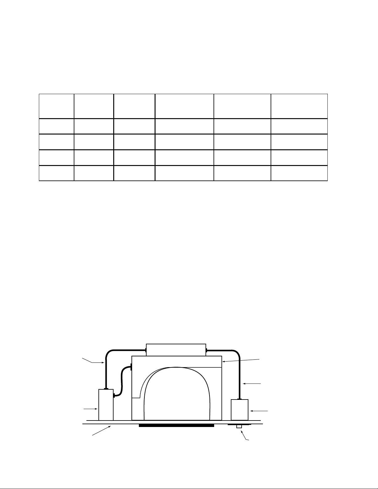
FLEX “A”
JUNCTION
BOX
CEILING
TILE
A.C. BALLAST &
LAMP SOCKET COMPARTMENT
FLEX “B”
SWITCH BOX
TEST SWITCH
CHARGE LIGHT
CAUTION: Before installing, make certain the A.C. power is off and the
ICE-420-EM-A unit connector is disconnected.
1. LAMPS OPERATED
Refer to the chart below for the type of lamp(s) operated and the number of lamps to be operated in the emergency mode.
If you have any questions regarding specific lamps, contact Customer Service.
*The 6″ violet leads provide the lamp selection option. The unit is shipped from the factory with the leads discon-
nected and capped. When used with particular lamp types, violet leads should be connected to one another. Refer
to chart for lamp selection options.
2. MOUNTING THE ICE-420-EM-A
When used with ceiling mounted downlight fixtures, the ICE-420-EM-A should be mounted on the fixture above
the ceiling. The flex conduit marked “A” should be wired into the ballast/lamp compartment or to an electrical junction box on the fixture which allows access to the ballast/lamp connections. Refer to Illustration 1 for typical mount-
ing.
When battery packs are remote mounted, consult Customer Service for the maximum allowable distance between
the battery pack and the lamp.
3. MOUNTING THE THREADED BODY TEST SWITCH (TBTS)
Cut a single gang switch box into the ceiling tile adjacent to the fixture within reach of the ICE-420-EM-A flex
marked “B”. After mounting the switch box, connect flex “B” to the box and route all leads inside the box. Refer to
Illustration 1 for typical mounting. NOTE: For proper operation, use only the test accessories provided with the
unit. See Page 1 of the Instruction Manual.
Illustration 1 Downlight Fixture
ICE-420-EM-A
TBTS
INSURE WIRING IS IN ACCORDANCE WITH THE NATIONAL ELECTRICAL CODE AND LOCAL REGULATIONS.
Page 2
 Loading...