

Page 1

ETS-STEP
EMERGENCY LIGHTING
CONTROL DEVICE
P.O. BOX 11846 TUCSON, AZ 85734
(520) 294-3292 • FAX (520) 741-2837
www.iotaengineering.com
INSTRUCTION MANUAL
IMPORTANT SAFEGUARDS
When using electrical equipment, basic safety precautions should always be followed, including the following:
READ AND FOLLOW ALL SAFETY INSTRUCTIONS
1. CAUTION – This fixture provides more than one power supply output source. To reduce the risk of electrical
shock, disconnect both normal and emergency sources by turning off the A.C. branch circuit.
2. CAUTION – This is a sealed unit. Replace the entire unit when necessary.
3. DO NOT USE OUTDOORS. The ETS-STEP is for use with grounded, UL Listed, indoor fixtures. Not for use in
heated air outlets or hazardous locations.
FOR STEP DIMMING
SERIES ALCR for 3A CIRCUIT
4. The ETS-STEP requires an unswitched A.C. power source of either 120 or 277 volts. Properly cap the
unused A.C. lead.
5. Do not mount near gas or electric heaters.
6. The ETS-STEP should be mounted in locations and at heights where it will not readily be subjected to tamper
ing by unauthorized personnel.
7. The ETS-STEP is compatible with all A.C. magnetic and electronic ballasts and drivers.
8. The ETS-STEP is for use in step-dimming applications and not designed for use with 0-10 volt dimming
controls. May be suitable for use in some 3-wire dimming applications. Contact Customer Service for more
information.
9. The use of accessory equipment not recommended by the manufacturer may cause an unsafe condition.
10. Do not use this equipment for other than intended use.
11. Install in accordance with the National Electrical Code and local regulations.
12. Installation and servicing should be performed by qualified personnel.
13. Lighting fixture manufacturers, electricians, and end-users need to ensure product system compatibility before
final installation.
SAVE THESE INSTRUCTIONS
-
Page 2
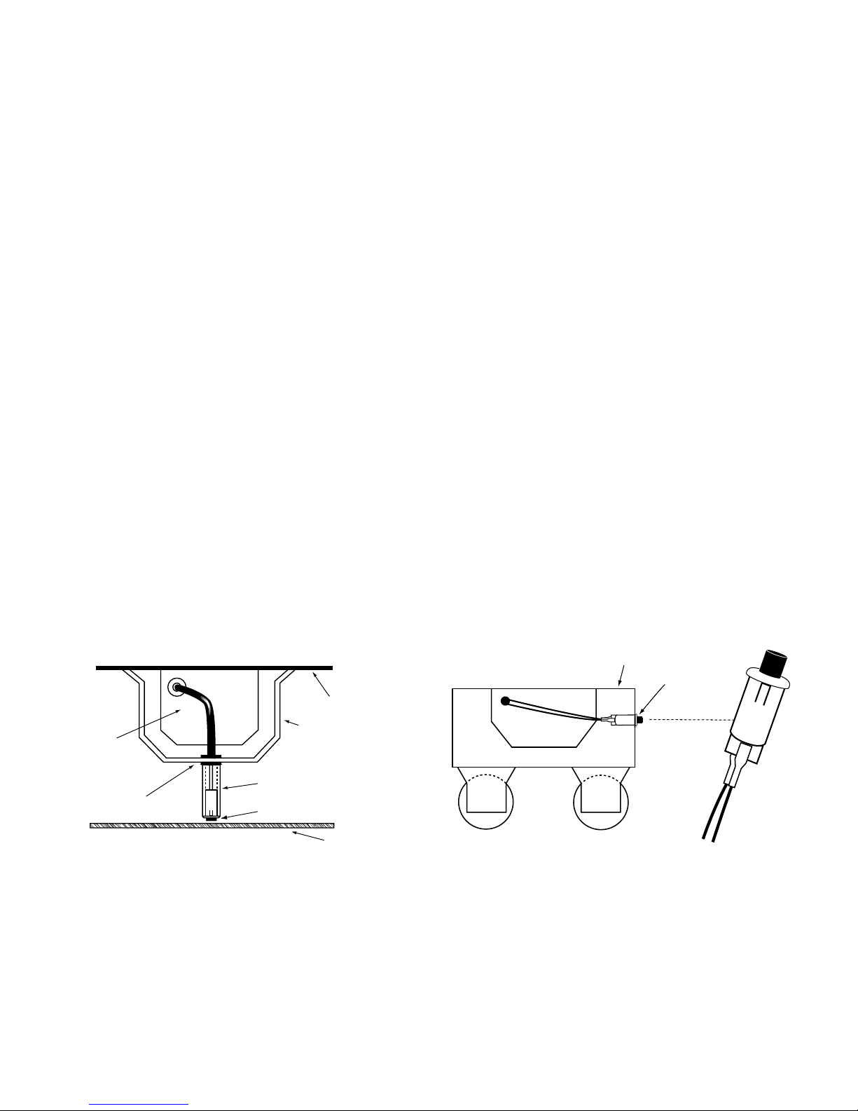
INSTALLATION INSTRUCTIONS
7/8" BUSHING
FIXTURE
BALLAST CHANNEL COVER
PLASTIC TUBE
CHARGE INDICATO R
LIGHT
FIXTURE LENS
FIXTURE
AC INDICATOR
+ RED
LEAD
WHITE/RED
LEAD
+ RED
CAUTION: Before installing, make certain the A.C. power is off.
1. MOUNTING THE ETS-STEP
Remove the driver channel cover. Mount the ETS-STEP in the ballast/driver channel at least ½″ away
from the A.C. ballast/driver(s).
2. WIRING
Refer to the wiring diagrams on the back page for the appropriate wiring of ballast/driver. Install in ac-
cordance with the National Electrical Code and local regulations. For additional wiring diagrams consult
Customer Service.
3. INSTALLING THE AC INDICATOR
Recessed Troffer Fixture – Select a convenient location with proper clearance in the ballast/driver
channel cover and drill or punch a 7/8″ hole (1/2″ knockout). Insert the 7/8″ bushing into the hole. Push the
plastic tube through the bushing. Disconnect the leads from the A.C. Indicator housing and route the
leads down the plastic tube. Reconnect the leads to the housing, observing the proper polarity (Yellow
lead to red marked or positive (+) red tab). Push the entire assembly back into the tube until the lens
collar rests against the plastic tube. The plastic tube should be adjusted so that the A.C. Indicator is
within ¼″ of the fixture lens. The A.C. Indicator must be visible after installation. Refer to Illustration 1.
Strip Fixture – Select a convenient location on the side of the fixture so the A.C. Indicator can be
seen after installation. Allow for proper clearance inside the fixture and drill or punch a ½″ hole. Disconnect the leads from the A.C. Indicator housing. Push the A.C. Indicator housing into the ½″ hole until it
is firmly locked in place. Reconnect the leads, observing the proper polarity (Yellow lead to red marked
or positive (+) red tab). Refer to Illustration 2.
Illustration 1 Recessed Troffer Fixture
ETS-STEP
LENS
4. WIRING THE A.C. INPUT
Refer to wiring diagrams on Page 4 for the proper wiring configuration of the ETS-STEP. For wiring
diagrams not shown, consult Customer Service.
Illustration 2 Strip Fixture
ETS-STEP
YELLOW/WHITE
OBSERVE PROPER POLARITY
LEAD
YELLOW
LEAD
Page 2
Page 3

OPERATION
Normal Mode – A.C. power is present. The A.C. driver or ballast operates the lamp(s) as intended. The
ETS-STEP allows operation of the luminaire at the desired dimmed setting by supplying the step-dimming
contacts on the A.C. Driver in accordance with the local control devices.
Emergency Mode
switches to the auxiliary power. The ETS-STEP Dimming Relay supplies all step-dimming contacts on the
A.C. ballast/driver, regardless of the position of the local control devices, forcing the luminaire to operate at full
lumen output. All lamps in the fixture are illuminated at full light output for as long as auxiliary power is available. When the A.C. power is restored, the ETS-STEP switches the system back to the Normal Mode. See
page 1 of the Instruction Manual.
– The A.C. power fails. The ETS-STEP senses the A.C. power failure and automatically
TESTING & MAINTENANCE
The ETS-STEP is a maintenance free unit, however, periodic inspection and testing is required. NFPA 101,
Life Safety Code, outlines the following schedule:
Insure that the A.C. Indicator light is illuminated monthly.
“Written records of testing shall be kept by the owner for inspection by the authority having jurisdiction.”
SERVICING SHOULD BE PERFORMED BY QUALIFIED PERSONNEL.
Consult Customer Service or visit www.iotaengineering.com for current warranty information.
Page 3
Page 4
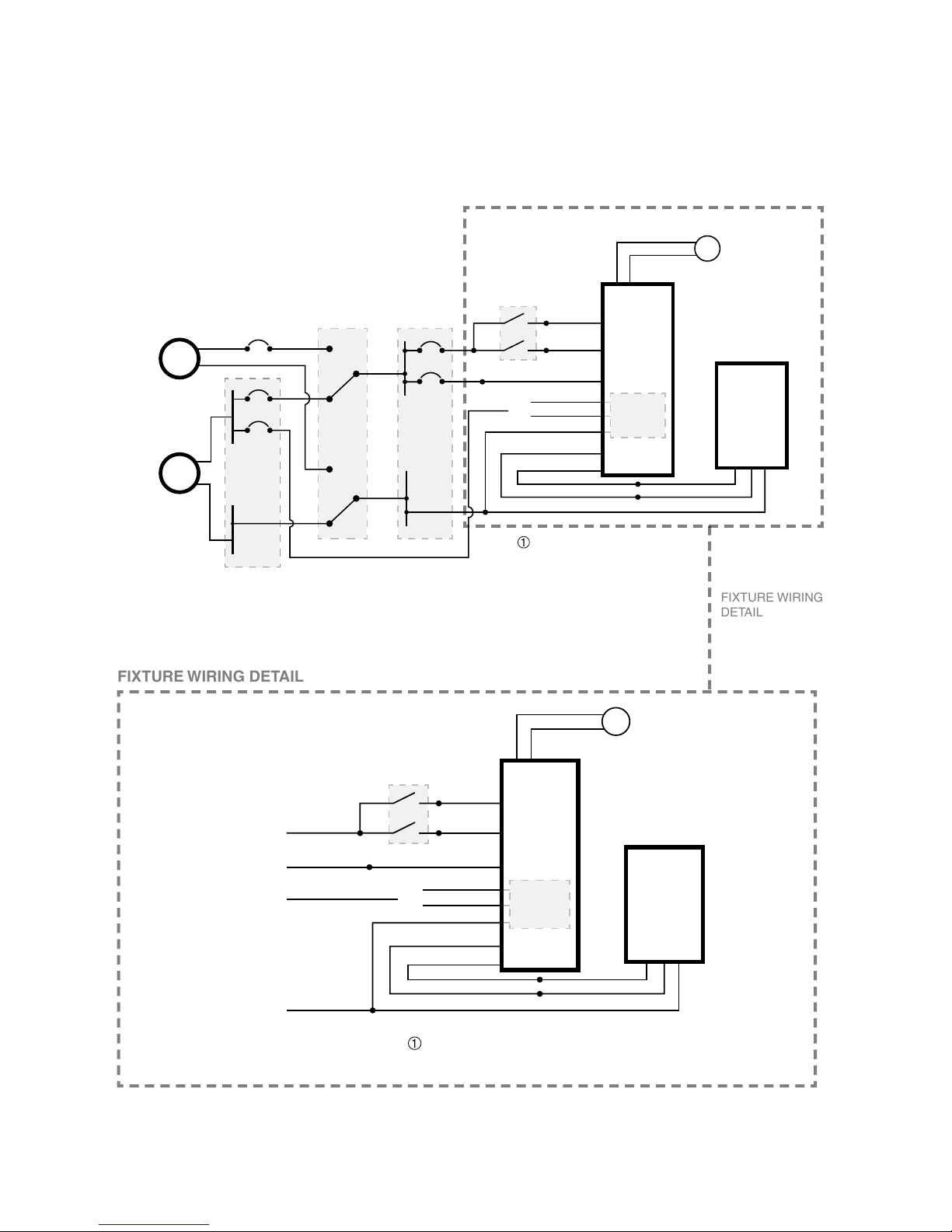
TYPICAL WIRING DIAGRAMS
TYPICAL SEPARATELY DERIVED SYSTEM (SWITCHED NEUTRAL) APPLICATION
YELLOW (+)
YELLOW/WHITE
ETS-STEP
EMERGENCY
CONTROL
DEVICE
AC DRIVER
/ BALLAST
RED LED
NORMAL POWER
INDICATOR
(OPTIONAL)
EMERGENCY
POWER
(GENERATOR)
NORMAL
SUPPLY
G
N
÷
HOT
HOT
NEUTRAL
NEUTRAL
BLACK (120V)
RED
BROWN (L2)
ORANGE (277V)
BLK/YEL (120/277V)
BLK/ORG (120/277V)
NORMAL POWER SENSE.
SELECT PROPER VOLTAGE
LEAD. CAP UNUSED LEAD.
NORMAL
PANEL
UL 1008 DEVICE EMERGENCY PANEL
TRANSFER SWITCH
CONTROL DEVICES
(WALL SWITCHES)
MONITOR
/ SENSE
NEUTRAL
WHITE
BLACK
BLACK
L1 L2
L1
L2
WHITE
HOT
HOT
NEUTRAL
BLUE (L1)
Note: This illustration shows a separately derived system (switched neutral). When the generator
is not a separately derived system, the neutral conductors are solidly interconnected.
YELLOW (+)
YELLOW/WHITE
ETS-STEP
EMERGENCY
CONTROL
DEVICE
AC DRIVER
/ BALLAST
RED LED
NORMAL POWER
INDICATOR
(OPTIONAL)
÷
BLACK (120V)
RED
BROWN (L2)
ORANGE (277V)
BLK/YEL (120/277V)
BLK/ORG (120/277V)
NORMAL POWER SENSE.
SELECT PROPER VOLTAGE
LEAD. CAP UNUSED LEAD.
CONTROL DEVICES
(WALL SWITCHES)
MONITOR
/ SENSE
L1 L2
L1
L2
WHITE
BLUE (L1)
EMERGENCY PANEL
HOT
EMERGENCY PANEL
NEUTRAL
NORMAL PANEL HOT
(NORMAL SUPPLY SENSE)
WHITE
BLACK
BLACK
FIXTURE WIRING DETAIL
FIXTURE WIRING
DETAIL
For wiring diagrams of ballast/drivers not shown, consult our Customer Service.
TYPICAL CIRCUIT DIAGRAM
SEPARATELY DERIVED SYSTEM (SWITCHED NEUTRAL)
Note: This illustration shows a separately derived system
(switched neutral). When the generator is not a separately derived system, the neutral conductors are solidly interconnected.
Rev. 1700
68014-104
Page 4
 Loading...