

IOTA EM1 User Manual
INSTALLATION MANUAL
FOR
EM1 AND EM1SD
DUAL-HEAD
P.O. BOX 11846 TUCSON, AZ 85734
(520) 294-3292 • FAX (520) 741-2837
www.iotaengineering.com
LED EMERGENCY LIGHT
IMPORTANT SAFEGUARDS
When using electrical equipment, basic safety precautions should always be followed, including the following:
READ AND FOLLOW ALL SAFETY INSTRUCTIONS
1. Installation and servicing should be performed by qualified personnel.
2. Install in accordance with the National Electrical Code and local regulations.
3. CAUTION – This fixture provides more than one power supply output source. To reduce the risk of electrical shock, disconnect
power by turning off the A.C. branch circuit, and follow the installation instructions in their proper sequence as outlined.
4. Not for use in heated air outlets or hazardous locations.
5. Do not mount near gas or electric heaters.
6. This unit uses a sealed valve regulated lead acid battery. Batteries can be punctured if not handled properly, therefore use
caution when servicing. In the event battery acid comes in contact with eyes or skin, flush with fresh water and consult a physician immediately.
7. The unit should be mounted in locations and at heights where it will not readily be subjected to tampering by unauthorized
personnel.
8. When using conduit, use flexible conduit only.
9. The use of accessory equipment not recommended by the manufacturer may cause an unsafe condition, void warranty, and
result in non-compliance with UL specifications.
10. Do not use this equipment for other than intended use.
11. This unit requires an unswitched A.C. power source of either 120 or 277 volts. Properly cap the unused A.C. lead.
12. Suitable for use in damp locations.
13. For use in 50° F minimum, 104° F maximum ( 10° - 40° C) ambient temperatures.
14. Allow battery 24 hours to charge before first use.
15. Electricians and end-users need to ensure proper operation before final installation.
SAVE THESE INSTRUCTIONS
CAUTION: Before installing, make certain
the A.C. power is switched off at the circuit
breaker panel.
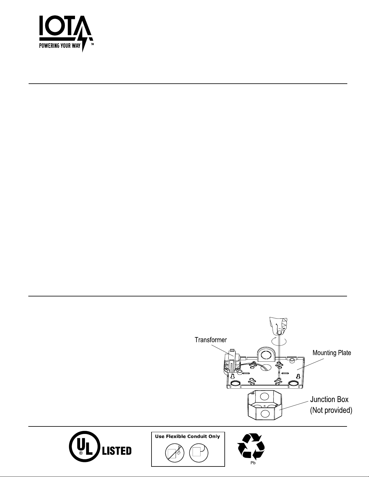
1. Mounting
For WALL MOUNTING, Remove the mounting plate
from the fixture by pressing on the pressure pads on
the bottom of the unit. Remove the desired knockouts
on the back of the mounting plate and push fixture
wires through the holes. After making electrical connections, securely attach the mounting plate to the
J-box using the screws provided. See Figure 1.
Fig. 1
THIS UNIT CONTAINS A
RECHARGEABLE VALVE-REGULATED
LEAD ACID BATTERY. PLEASE
RECYCLE OR DISPOSE OF
PROPERLY.
1. Mounting (cont.)
BATTERY
TO PCB ASSEMBLY
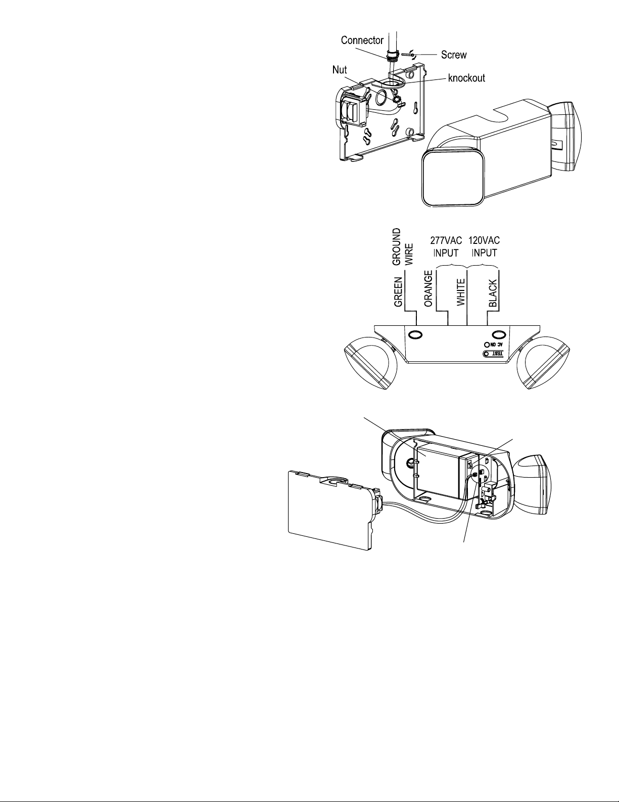
For CEILING MOUNTING, Remove the mounting plate
from the fixture by pressing on the pressure pads on the
bottom of the unit. Remove the top knockouts on both
the mounting plate and the top of the fixture. Secure the
mounting plate to the rigid electrical conduit using a screw,
pipe connector, and nut (not provided). See Fig. 2
2. Electrical Connections
A) Connect the WHITE wire lead from the fixture to the
NEUTRAL wire supply feed from the circuit. Connect either the BLACK (120V) or ORANGE (277V),
depending on supply voltage, to the BLACK (Hot)
wire from the supply circuit. See Fig. 3. Use only UL
Listed wire connectors suitable for the size, type,
and number of conductors. CAP ALL UNUSED
LEADS. No loose strands or uncapped wires should
be present. Secure wire connectors with UL Listed
electrical tape.
B) Connect the transformer to the PCB Assembly, as
shown in Fig. 4
C) Connect the spade connector of the RED Lead to
the battery’s POSITIVE (red) terminal (Fig. 4).
Fig. 2
Fig. 3
3. Completing Installation
Snap the fixture onto the mounting plate and ensure no
wires are pinched. Make sure the unit is fully and firmly
attached.
Restore AC power. The AC indicator on the fixture
will be lit. To test the unit, press the test button. The
Fig. 4
CONNECT RED LEAD
FROM PCB ASSEMBLY TO
BATTERY TERMINAL
battery-powered lamps will come on and the AC Indicator will turn off.
CONNECT TRANSFORMER
Testing and Maintenance
Pressing the Test Button turns off the AC Indicator light and forces the unit into emergency mode and activates the
lamps. After releasing the Test Button, the fixture returns to normal operation.
Initial Testing – Allow the unit to charge approximately 1 hour, then press the test switch to conduct a short discharge
test. Allow a 24 hour charge before conducting a one hour test.
This is a maintenance free unit, however, periodic inspection and testing is required. NFPA 101, Life Safety Code, outlines the following schedule:
Monthly – Insure that the AC indicator is illuminated. Conduct a 30 second discharge test by depressing the Test Button.
The lamps on the unit should be lit.
Annually – Insure that the AC indicator is illuminated. Conduct a full 11/2 hour discharge test. The unit should operate as
intended for the duration of the test.
“Written records of testing shall be kept by the owner for inspection by the authority having jurisdiction.”
Contact Customer Service or visit www.iotaengineering.com for current warranty information.
68901-000 REV 1400
SERVICING SHOULD BE PERFORMED BY QUALIFIED PERSONNEL.
Page 2
 Loading...