

ETS-DR
SERIES 924
P.O. BOX 11846 TUCSON, AZ 85734
(520) 294-3292 • FAX (520) 741-2837
www.iotaengineering.com
INSTRUCTION MANUAL
IMPORTANT SAFEGUARDS
When using electrical equipment, basic safety precautions should always be followed, including the following:
READ AND FOLLOW ALL SAFETY INSTRUCTIONS
1. CAUTION – This fixture provides more than one power supply output source. To reduce the risk of electrical
shock, disconnect both normal and emergency sources by turning off the AC branch circuit.
2. CAUTION – This is a sealed unit. Replace the entire unit when necessary.
3. DO NOT USE OUTDOORS. The ETS-DR is for use with grounded, UL Listed, indoor fixtures. Not for use in
heated air outlets or hazardous locations.
EMERGENCY LIGHTING
CONTROL DEVICE
4. Do not mount near gas or electric heaters.
5. The ETS-DR should be mounted in locations and at heights where it will not readily be subjected to tampering
by unauthorized personnel.
6. The ETS-DR is compatible with all AC magnetic and electronic ballasts and drivers.
7. The ETS-DR is for use in 0-10 volt dimming applications only, and not designed for use with 3-wire dimming or
step dimming ballasts. The maximum current of the dimming circuit must not exceed 100 mA.
8. The use of accessory equipment not recommended by the manufacturer may cause an unsafe condition.
9. Do not use this equipment for other than intended use.
10. Install in accordance with the National Electrical Code and local regulations.
11. Installation and servicing should be performed by qualified personnel.
12. Lighting fixture manufacturers, electricians, and end-users need to ensure product system compatibility before
final installation.
SAVE THESE INSTRUCTIONS
INSTALLATION INSTRUCTIONS
7/8" BUSHING
FIXTURE
BALLAST CHANNEL COVER
PLASTIC TUBE
CHARGE INDICATOR
LIGHT
FIXTURE LENS
FLEX
CEILING
TILE
LED DRIVER AND ARRAY
COMPARTMENT
TBTS
CAUTION: Before installing, make certain the AC power is off.
1. MOUNTING THE ETS-DR
Integral (No Flex) – Remove the driver channel cover. Mount the ETS-DR in the ballast/driver channel
at least ½″ away from the AC driver(s).
Flex (ETS-DR-A) – Mount the ETS-DR-A on or adjacent to the fixture in a position that does not interfere
with the existing AC ballast/driver or any other hardware. Extend the flex conduit to the junction box or
wireway channel and punch a 7/8″ hole. Feed the wires and flex connector down through the hole in the
fixture and secure in place with the flex connector nut.
2. WIRING
Refer to the wiring diagram on the back page for the appropriate wiring of the ETS-DR. Install in ac-
cordance with the National Electrical Code and local regulations. For additional wiring diagrams consult
Customer Service.
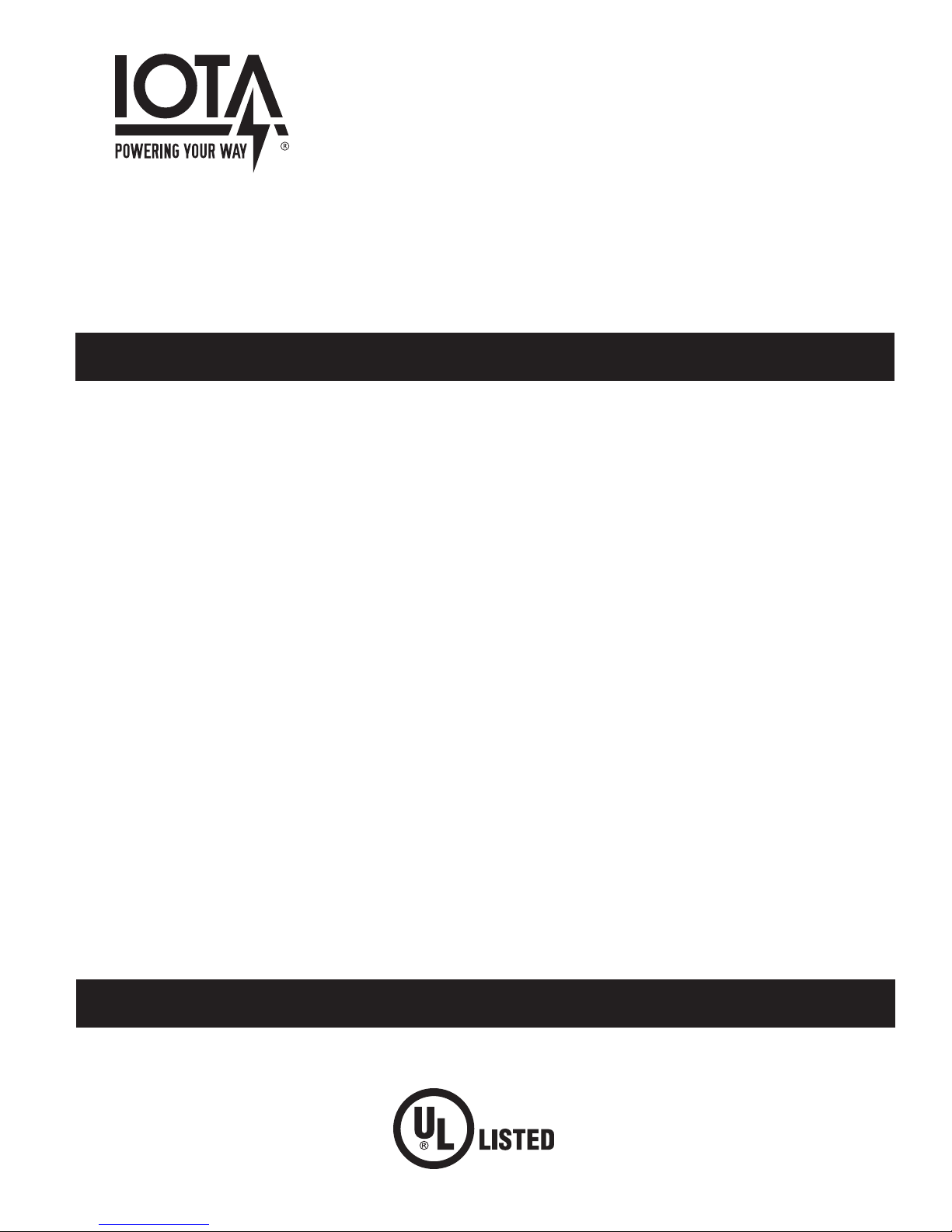
3. INSTALLING THE AC INDICATOR
Integral (No Flex) – Select a convenient location with proper clearance in the ballast/driver channel
cover and drill or punch a 7/8″ hole (1/2″ knockout). Insert the 7/8″ bushing into the hole. Push the plastic
tube through the bushing. Disconnect the leads from the AC Indicator housing and route the leads
down the plastic tube. Reconnect the leads to the housing, observing the proper polarity (Yellow lead
to red marked or positive (+) red tab). Push the entire assembly back into the tube until the lens collar
rests against the plastic tube. The plastic tube should be adjusted so that the AC Indicator is within
¼″ of the fixture lens. The AC Indicator must be visible after installation. Refer to Illustration 1 for an
example of integral mounting in a recessed troffer fixture.
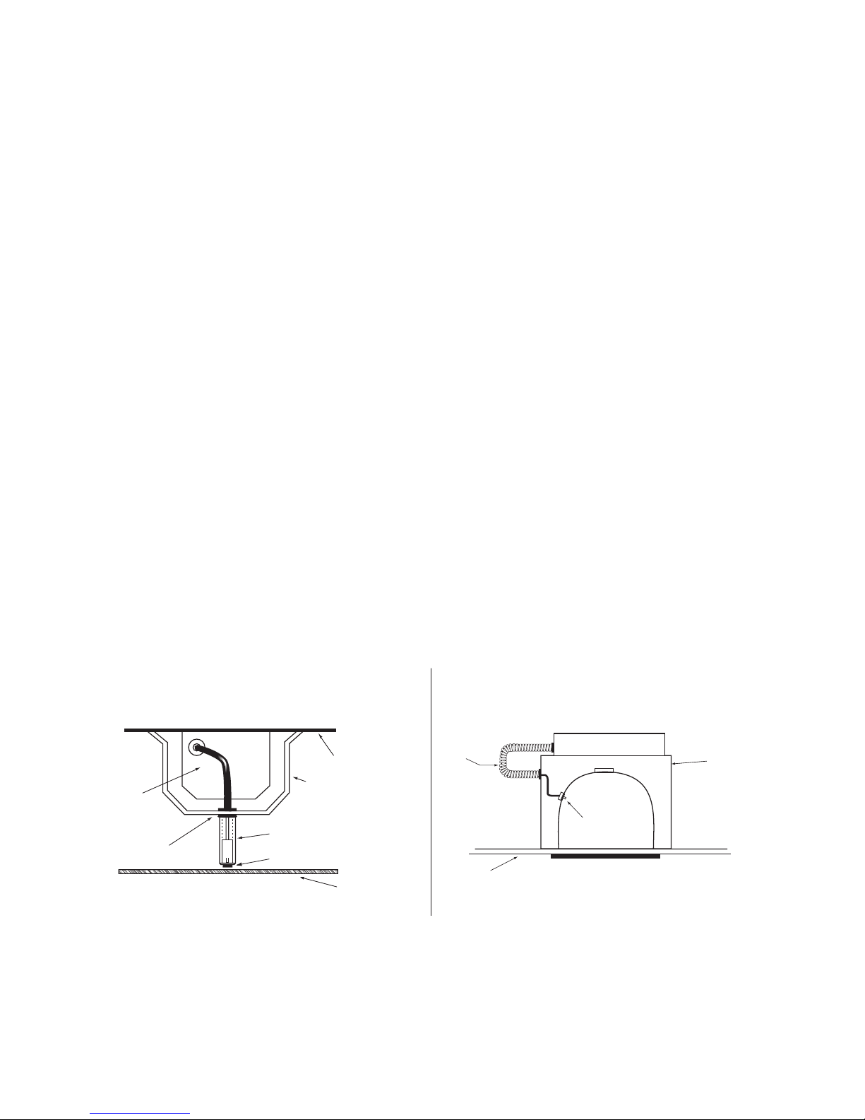
Flex (ETS-DR-A) – Select a convenient location on the fixture so the AC Indicator can be seen after
installation. Allow for proper clearance inside the fixture and drill or punch a ½″ hole. Disconnect the
leads from the AC Indicator housing. Push the AC Indicator housing into the ½″ hole until it is firmly
locked in place. Reconnect the leads, observing the proper polarity (Yellow lead to red marked or positive (+) red tab). Refer to Illustration 2 for an example of mounting on a downlight fixture.
Illustration 1: Integral (No Flex) Mounting
Recessed Troffer Fixture
ETS-DR
Illustration 2: Flex (ETS-DR-A) Mounting
Downlight Fixture
ETS-DR-A
CHARGE INDICATOR
LIGHT
OBSERVE PROPER POLARITY
AC DRIVER/BALLAST
COMPARTMENT
Page 2
 Loading...