

Page 1
I.O.T WORKSHOP
Eport Pro-EP10 Super Port User Manual
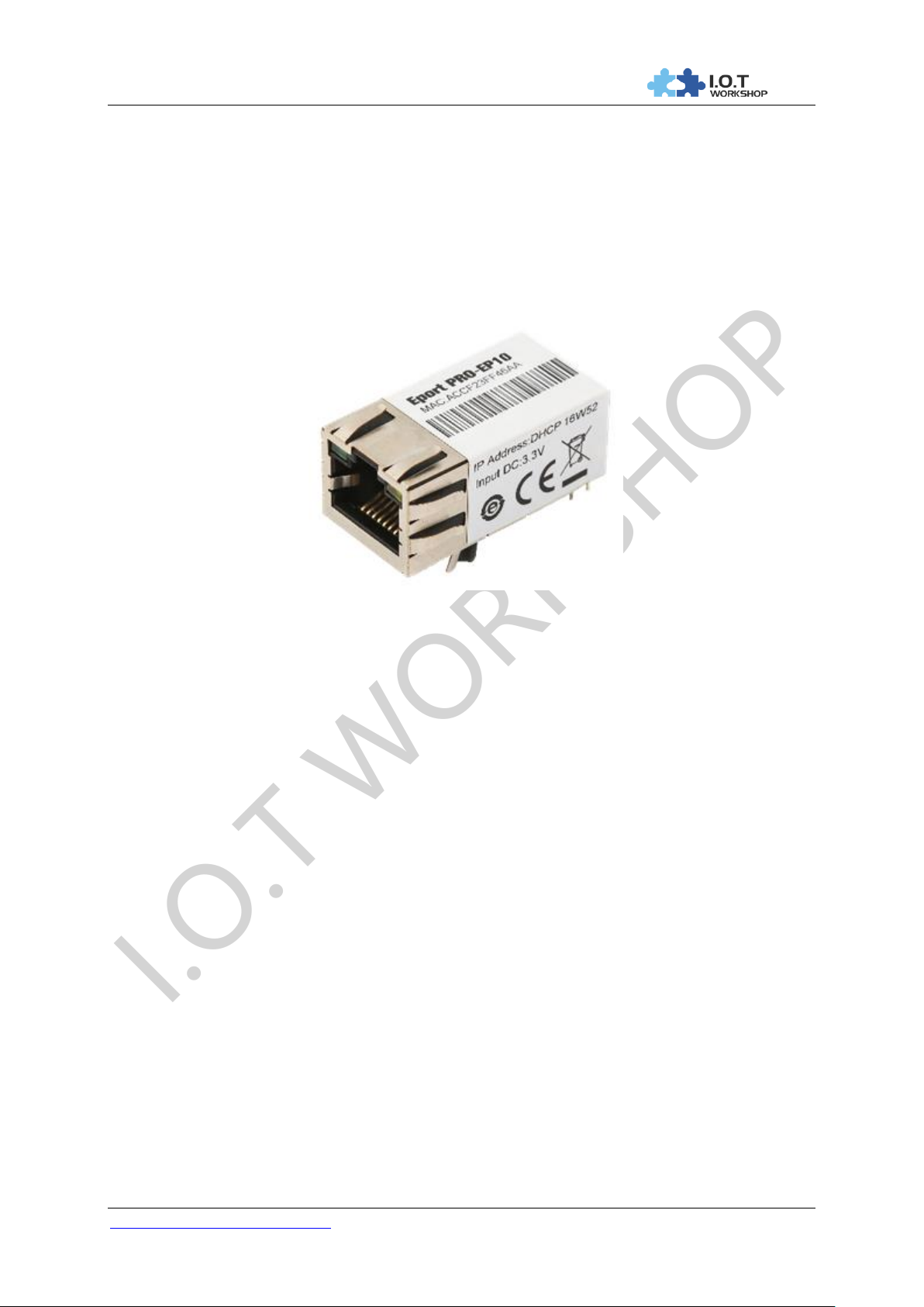
Eport Pro-EP10
Super Port User Manual
V 1.0
Overview of Characteristic
MIPS MCU with 16MB Flash and 32MB SRAM
Use Linux Operation System
Support TCP/IP/Telnet /Modbus TCP Protocol
Support Serial To 10/100M Ethernet Conversion, Serial Speed Upto 460800 bps
Support 10/100M Ethernet Auto-Negotiation
Support Easy Configuration Through a Web Interface
Support Security Protocol Such As SSL/AES/DES3
Support Web OTA Wirelss Upgrade
Single +3.3V Power Supply
Size: 33 x 18.6 x 15 mm (L x W x H)
FCC/CE/RoHS Certificated
http://www.iotworkshop.com - 1 -
Page 2

I.O.T WORKSHOP
Eport Pro-EP10 Super Port User Manual
TABLE OF CONTENTS TABLE OF CONTENTS
TABLE OF CONTENTS TABLE OF CONTENTS ........................................................................... 2
LIST OF FIGURES ............................................................................................................................ 3
LIST OF TABLES ............................................................................................................................. 4
HISTORY ........................................................................................................................................... 4
1. PRODUCT OVERVIEW ........................................................................................................ 5
1.1. General Description ......................................................................................................... 5
1.2. Device Features ............................................................................................................... 5
1.3. Device Paremeters ........................................................................................................... 6
1.4. Key Application ................................................................................................................ 7
2. HARDWARE INTRODUCTION ........................................................................................... 8
2.1. Pins Definition .................................................................................................................. 8
2.2. Electrical Characteristics ..............................................................................................10
2.3. Ethernet Interface ..........................................................................................................10
2.4. Ethernet LED Interface ..................................................................................................11
2.5. Mechanical Size .............................................................................................................11
2.6. Recommended PCB Layout ..........................................................................................11
2.7. Evaluation Kits ...............................................................................................................12
2.8. Order Information ..........................................................................................................13
2.9. Typical Application ........................................................................................................13
3. PACKAGE INFORMATION ............................................................................................... 14
3.1. Recommended Solding .................................................................................................14
3.2. Shipping Information .....................................................................................................14
3.3. EVK Shipping Information ............................................................................................14
APPENDIX A: HW REFERENCE DESIGN ............................................................................... 16
APPENDIX B: CONTACT INFORMATION ............................................................................... 17
http://www.iotworkshop.com - 2 -
Page 3

I.O.T WORKSHOP
Eport Pro-EP10 Super Port User Manual
LIST OF FIGURES
Figure 1. Eport Pro-EP10 Appearance .......................................................................................................... 8
Figure 2. Eport Pro-EP10 Pins Map ................................................................................................................ 8
Figure 3. Eport Pro-EP10 Mechanical Dimension ......................................................................................... 11
Figure 4. Eport Pro-EP10 PCB Layout .......................................................................................................... 11
Figure 5. Eport Pro-EP10 EVK ..................................................................................................................... 12
Figure 6. Eport Pro-EP10 Product Number Defination.................................................................................. 13
Figure 7. Eport Pro-EP10 Hardware Typical Application .............................................................................. 13
Figure 8. Shipping information ...................................................................................................................... 14
Figure 9. Shipping Information ................................................................ ...................................................... 14
Figure 10. HW REFERENCE DESIGN ........................................................................................................... 16
http://www.iotworkshop.com - 3 -
Page 4

I.O.T WORKSHOP
Eport-E10 Serial Server User Manual
LIST OF TABLES
Eport Pro-EP10 Module Technical Specifications .................................................................................. 6 Table1.
Eport Pro-EP10 Pins Definition............................................................................................................... 8 Table2.
Absolute Maximum Ratings: ................................................................................................................. 10 Table3.
Power Supply & Power Consumption: .................................................................................................. 10 Table4.
Ethernet Interface Definition ................................................................................................................. 10 Table5.
LED Interface Definition ........................................................................................................................ 11 Table6.
Eport Pro-EP10 EVK Interface ............................................................................................................. 12 Table7.
HISTORY
Ed. V1.0 10-21-2016 First Version
Shanghai High-Flying Electronics Technology Co., Ltd - 4 -
Page 5

I.O.T WORKSHOP
Eport-E10 Serial Server User Manual
1. PRODUCT OVERVIEW
1.1. General Description
The Eport Pro-EP10 is a fully self-contained small form-factor, most compact, integrated solution,
which provide a serial interface to Ethernet connectivity to web enable any device. The Eport ProEP10 integrate TCP/IP controller, memory, 10/100M Ethernet transceiver, high-speed serial port
within a compact RJ45 package and integrates a fully developed TCP/IP network stack and Linux
OS.The Eport Pro-EP10 also includes an embedded web server used to remotely configure, monitor,
or troubleshoot the attached device.
The Eport Pro-EP10 using highly integrated hardware and software platform,It has been optimized for
all kinds of applications in the industrial control, smart grid , personal medical application and remote
control that have lower data rates, and transmit or receive data on an infrequent basis. By simply
adding an Eport Pro-EP10 unit to a product Design, device manufacturers can reduce their Design
cycle and speed up Time-To-Market with very low risk.
The Eport Pro-EP10 integrates all serial to Ethernet functionality into a low-profile, 33 x 18.6 x 15mm
standard RJ45 module package that can be easily mounted on main PCB with application specific
circuits and even not change your original Design.
1.2. Device Features
MIPS MCU with 8MB Flash and 32MB SRAM
Full Integrated RJ45 Solution
Support Linux Operation System
Support TCP/IP、UDP、DHCP、DNS、HTTP Server/Client、ARP、BOOTP、AutoIP、ICMP、
Telnet、FTP、TFTP、uPNP、NTP、ModbusTCP Protocol
Support Serial to 10/100M Ethernet Conversion, Serial Speed Upto 460800 bps
Support 10/100M Ethernet Auto-Negotiation
Support Easy Configuration Through a Web Interface
Support Security Protocol Such As SSL/AES/DES3
Support Web Wireless Upgrade
Single +3.3V Power Supply
Size: 33 x 18.6 x 15mm (L x W x H)
FCC/CE/RoHS Certificated
Shanghai High-Flying Electronics Technology Co., Ltd - 5 -
Page 6

I.O.T WORKSHOP
Eport-E10 Serial Server User Manual
Item
Parameters
System Information
Processor/Frequency
MIPS/320MHz
Flash/SDRAM
16MB/32MB
Operating System
Linux
Ethernet Port
Port Number
1 RJ45 with LED
Interface Standard
10/100 Base-T Auto-Negotiation
Protection
2KV Isolation
Transformer
Integrated
Network Protocol
IP,TCP,UDP,DHCP,DNS,HTTP Server/Client,ARP,
BOOTP, AutoIP, ICMP,Web socket, Telnet, FTP,TFTP,
uPNP, NTP, SNMP,Modbus TCP
Security Protocol
SSL v3(2048)、
AES 128Bit、3DES、
SHA-1、MD5、Base-64、RSA、ECC
IPV6 Support
Support
Serial Port
Port Number
1 + 1 debug
Interface Standard
3.3V TTL: 2 wire(TX,RX)
Data Bits
5,6,7,8
Stop Bit
1,2
Check Bit
None,Even,Odd,Space,Mark
Baud Rate
TTL: 600 bps~460800 bps
Flow Control
No Flow control
Hardware RTS/CTS、DSR/DTR
Software Xon/ Xoff flow control
Software
Web Pages
Http Web Configuration
Customization of HTTP Web Pages
Log
Remote Realtime Log,
Configuration
Web
CLI
XML import
Telnet
IOTManager PC Software
Firmware Upgrade
Web
SDK For Dev.
提供
Basic Parameter
Size
33 x 18.6 x 15 mm
Operating Temp.
-25 ~ 70°C
Storage Temp.
-45 ~ 105°C, 5 ~ 95% RH(no condensation)
Input Voltage
3.3V
Working Current
~200mA
1.3. Device Paremeters
Eport Pro-EP10 Module Technical Specifications Table1.
Shanghai High-Flying Electronics Technology Co., Ltd - 6 -
Page 7

I.O.T WORKSHOP
Eport-E10 Serial Server User Manual
Power
<700mW
Other Information
Certificate
CE, FCC, RoHS
Material
Metal shell, thermoplastic case
1.4. Key Application
The Eport Pro-EP10 device connects serial device to Ethernet networks using the TCP/IP protocol:
Remote equipment monitoring
Asset tracking and telemetry
Security Application
Industrial sensors and controls
Medical devices
ATM machines
Data collection devices
Universal Power Supply (UPS) management units
Telecommunications equipment
Data display devices
Handheld instruments
Modems
Time/attendance clocks and terminals
Shanghai High-Flying Electronics Technology Co., Ltd - 7 -
Page 8
I.O.T WORKSHOP
Eport-E10 Serial Server User Manual
Pin
DES3cribtion
Net Name
Signal Type
Comments
1
GPIO
GPIO1
I/O
Can be configured to UART1:TXD2
2
GPIO
GPIO2
I/O
Can be configured to UART1:RXD2
2. HARDWARE INTRODUCTION
The Eport Pro-EP10 unit is a complete solution for serial port device connecting to network.
Packageed into a RJ45 connector, this powerful device supports a 10/100BASE-T Ethernet
connection, a reliable and proven operating system stored in flash memory, an embedded web server,
a full TCP/IP protocol stack,and standards-based (AES) encryption.
Through Ethernet cable connect router with Eport –E10 serial server for data transfer, which makes
the electromechanical integration very simple. Eport Pro-EP10 meet EMC Class B security level,It can
pass every countries relevant certification test
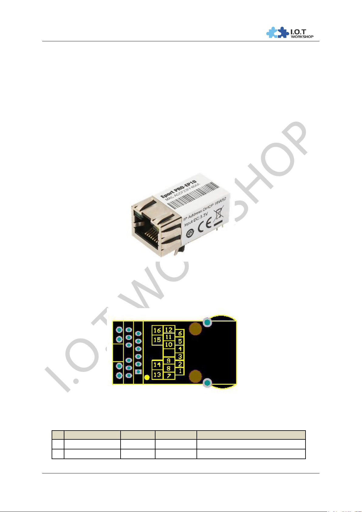
Figure 1. Eport Pro-EP10 Appearance
2.1. Pins Definition
Figure 2. Eport Pro-EP10 Pins Map
Eport Pro-EP10 Pins Definition Table2.
Shanghai High-Flying Electronics Technology Co., Ltd - 8 -
Page 9

I.O.T WORKSHOP
Eport-E10 Serial Server User Manual
Pin
DES3cribtion
Net Name
Signal Type
Comments
3
UART0
CTS O Can be configured to GPIO
4
External Reset In
nRST
I, PU
“Low” effective reset input.
5
UART0
RTS I Can be configured to GPIO
6
Multi-Function Pin
nReload
I,PU
Detailed functions see <Notes>
7
LED indicator
LED2_Data
O
If use product’s LED, must connect this
Pin to Pin13,
If don’t use the product’s LED, may
connect this Pin to external LED circuit.
Detailed functions see <Notes>
8
UART0
RXD
I
3.3V, TTL.
9
UART0
TXD
O
3.3V, TTL.
10
Ground
GND
GND
Power Ground
11
+3.3V Power
DVDD
Power
+3.3V
12
LED indicator
LED1_Link
O
If use product’s LED, must connect to
Pin16.
If don’t use the product’s LED, may
connect this Pin to external LED circuit.
Detailed functions see <Notes>
13
LED indicator
LED2
I
If use product’s LED, connect to Pin7.
If not use the product’s LED, leave it
unconnected.
14
LED power
LED_3V3
Power
LED_Data Power 3.3V, If don’t use the
product’s LED, leave it unconnected.
15
LED power
LED_3V3
Power
LED_Link Power 3.3V, If don’t use the
product’s LED, leave it unconnected.
16
LED indicator
LED1
I
If use product’s LED, connect to Pin12.
If don’t use the product’s LED, leave it
unconnected.
<Notes>
nReload Pin function:
1. Put this pin low before the device powered on (or Reset), This device works in mass
production mode to upgrade its firmware, this mode is used for upgrade customized
firmware. The corresponding PC tools can be download on High Flying website.
2. After device is powered up, If put this pin to low more than 3 seconds and then put to High,
It will restore the product parameters to factory setting.
We strongly suggest user to fan out this pin.
LED2_Data Pin
1. When there are data transmiting and receiving, This LED will flashing. If there is no data
transmit and receive, It will output High.
LED1_Link Pin
1. When Ethernet connected normal, It will output Low, If there is no Ethernet connection, It
will output High.
Shanghai High-Flying Electronics Technology Co., Ltd - 9 -
Page 10
I.O.T WORKSHOP
Eport-E10 Serial Server User Manual
Parameter
Condition
Min.
Typ.
Max.
Unit
Storage Temperature Range
-45 125
°C
Maximum Soldering Temperature
IPC/JEDEC J-STD-020
260
°C
Supply Voltage
0 3.8
V
Voltage on any I/O pin
0
3.3
V
ESD (Human Body Model HBM)
TAMB=25°C
2
KV
ESD (Charged Device Model, CDM)
TAMB=25°C
1
KV
Parameter
Condition
Min.
Typ.
Max.
Unit
Operating Supply Voltage
3.1
3.3
3.6
V
Operating Temperature Range
-45 70
°C
Supply Current (10BASE-T activity)@ 96MHz
Without date
transmit and
receive
150
mA
Supply Current (100BASE-T activity)@ 96MHz
5KB/S data
200
mA
Input Leakage Current
Ii
-10 10
uA
Output high voltage
@IOH=2mA
2.8 V Output Low Voltage
@IOL=2mA
0.3
V
Input High Voltage
1.6 3.6 V Input Low Voltage
-0.3
1.4 V GPIO Input pull-up resistor
200
kΩ
GPIO Input pull-down resistor
200
kΩ
Pin
DES3cribtion
Net Name
Signal Type
1
Transmit Data +
TX+
O
2
Transmit Data -
TX-
O
3
Receive Data +
RX+
I
4
NC
5
NC
6
Receive Data -
RX-
I
7
NC
8
NC
9
Case Ground
SHIELD
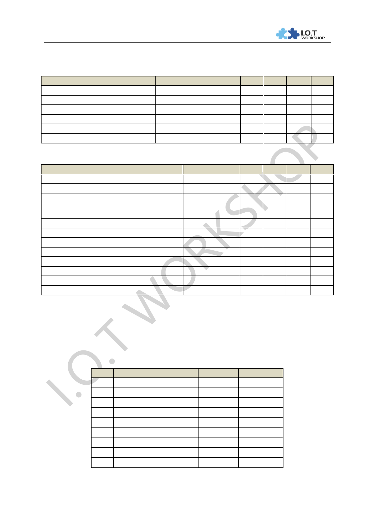
2.2. Electrical Characteristics
Absolute Maximum Ratings: Table3.
Power Supply & Power Consumption: Table4.
2.3. Ethernet Interface
The 10/100 Ethernet magnetics, network status LEDs, and RJ45 connector are all integrated into the
Eport Pro-EP10 unit.
Ethernet Interface Definition Table5.
Shanghai High-Flying Electronics Technology Co., Ltd - 10 -
Page 11
I.O.T WORKSHOP
Eport-E10 Serial Server User Manual
Link LED (Left Side)
Activity LED (Right Side)
Color
Meaning
Color
Meaning
Off
No Connection
Off
No Data
Green
10/100Mbps
Yellow
Have Data
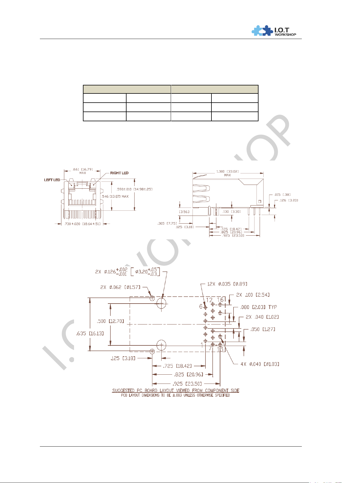
2.4. Ethernet LED Interface
The device contains two bi-color Ethernet LED indicator (Detailed postion is in dimension drawing .)
LED Interface Definition Table6.
2.5. Mechanical Size
The dimensions of Eport Pro-EP10 are defined as following picture (mm):
Figure 3. Eport Pro-EP10 Mechanical Dimension
2.6. Recommended PCB Layout
PCBA should have approximately 2.54cm x 2.54cm large plane GND to connect with product GND for
heat dissipation, The device’s metal shell is also a important way of heat dissipation.
Shanghai High-Flying Electronics Technology Co., Ltd - 11 -
Figure 4. Eport Pro-EP10 PCB Layout
Page 12
I.O.T WORKSHOP
Eport-E10 Serial Server User Manual
Function
Name
DES3cribe
External
Interface
COM
Main data/command RS-232 interface
USB_UART
UART to USB debug interface(Used for PC debug
envirement which without RS232 interface, Need load
drivers to use), Can be power supply port
DC5
DC 5V input
EXT PORT
GPIO Pin interface
JMP
4Pin USB or RS232 jumper.
All jump to left choose USB Serial..
All jump to right choose RS232
LED
Power
3.3V Power Indicate
Link
Network indicator, Detailed functions see
LED1_Link Pin<Notes>
Data
Communication indicator, Detailed functions see
LED2_Data Pin<Notes>
Button
Reset
“Reset” Button
Reload
Press down the button more than 3s and then loose
to restore factory setting
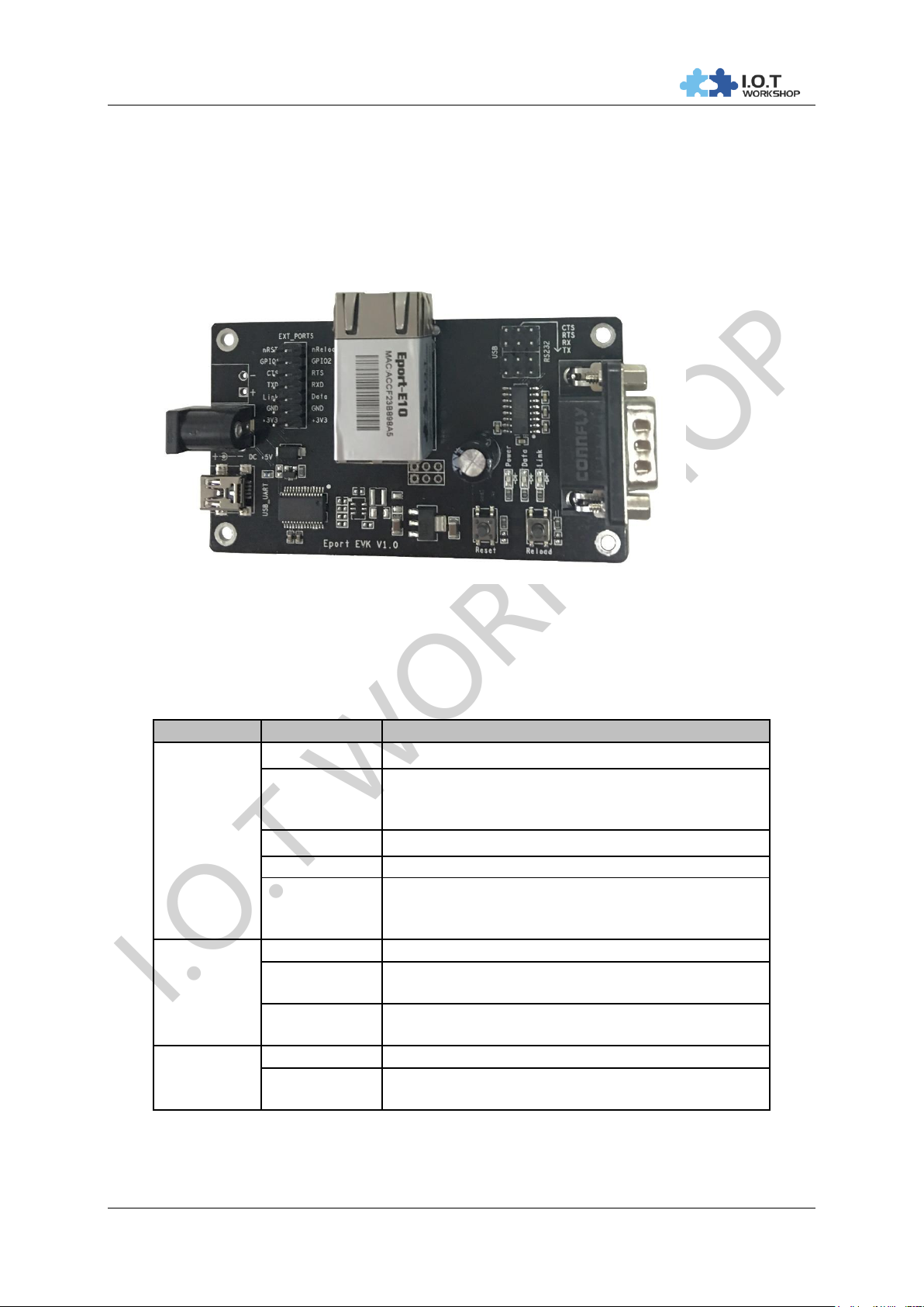
2.7. Evaluation Kits
We provide evaluation kit for user to learn to use Eport Pro-EP10. Evaluation kit picture is as following,
User can use RS232, USB Serial or Ethernet interface to configure parameters, manage equipment
and do some function test. ( onboard FT232R chip switch, its driver can be download from high flying
website, When using USB Serial, the top right corner jumper need to all jump to the left side). .
Figure 5. Eport Pro-EP10 EVK
Evaluation kit interface details as following:
Eport Pro-EP10 EVK Interface Table7.
Shanghai High-Flying Electronics Technology Co., Ltd - 12 -
Page 13
I.O.T WORKSHOP
Eport-E10 Serial Server User Manual
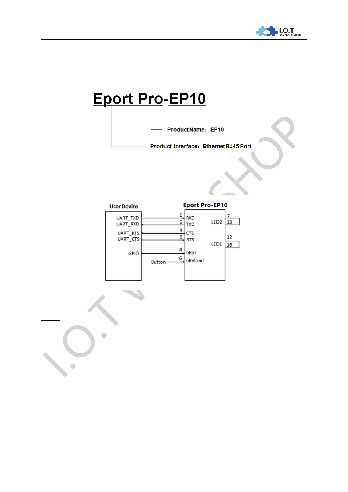
2.8. Order Information
Base on customer detailed requirement, Eport Pro-EP10 provide different configuration version,
Details as below:
Figure 6. Eport Pro-EP10 Product Number Defination
2.9. Typical Application
Figure 7. Eport Pro-EP10 Hardware Typical Application
Notes:
nRST- Input.Hardware reset signal. Effective Low.
There is internal pull-up resistor to 3.3V and no external pull-up resistor needed. MCU put nRST signal
to low for at least 10ms if need to reset the device.
nReload- Input.Device restore to factory default configuration. Effective Low; (Recommend this pin
to connect button or jumper header, Used for batch upgrade and configuration)
Can connect with external button or chip pin, When press nReload button, pull the pin to Low level
more than 3s, then loose, device will restore to factory default setting and restart itself. If nReload
function is not required, Can leave this pin open, Don’t need any connection.
TXD/RXD- UART port data transmit and receive signal.
Shanghai High-Flying Electronics Technology Co., Ltd - 13 -
Page 14
I.O.T WORKSHOP
Eport-E10 Serial Server User Manual
3. PACKAGE INFORMATION
3.1. Recommended Solding
Wave solding, temperate less than 180℃.
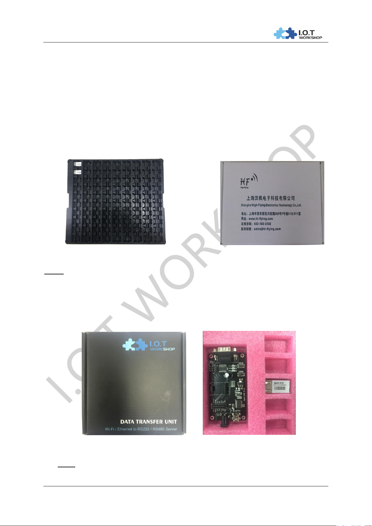
3.2. Shipping Information
Tray Box
Size:396*347*24 mm Size: 420x370x270 mm
Figure 8. Shipping information
Notes:
1 tray = 90pcs
1 box= 10 tray=10 X 90=900pcs
3.3. EVK Shipping Information
Figure 9. Shipping Information
Note:
1 box includes the following accessories.
Shanghai High-Flying Electronics Technology Co., Ltd - 14 -
Page 15

I.O.T WORKSHOP
Eport-E10 Serial Server User Manual
Shanghai High-Flying Electronics Technology Co., Ltd - 15 -
Page 16
I.O.T WORKSHOP
Eport-E10 Serial Server User Manual
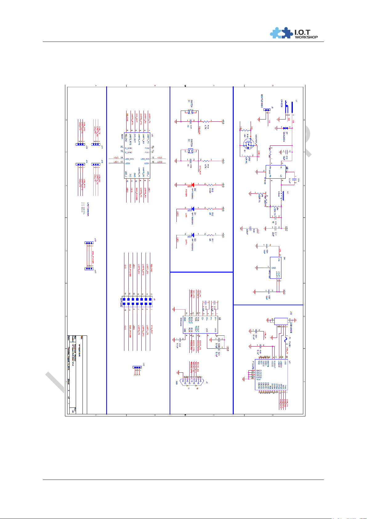
APPENDIX A: HW REFERENCE DESIGN
Figure 10. HW REFERENCE DESIGN
Detailed Eport Pro-EP10 Evluation Board Design source files, pls access IOTworkshop or High-Flying
web download page or contact with High-Flying technical support people to acquire.
Shanghai High-Flying Electronics Technology Co., Ltd - 16 -
Page 17

I.O.T WORKSHOP
Eport-E10 Serial Server User Manual
APPENDIX B: CONTACT INFORMATION
-----------------------------------------------------------------------------------------------------------Address: Room 1002,Building 1,No.3000,Longdong Avenue,Pudong New
Area,Shanghai,China,201203
Web: www.iotworkshop.com or www.hi-flying.com
Contact:
Sales: [email protected]
Support: [email protected]
Service: [email protected]
Business: [email protected]
---------------------------------------------------------------------------- -------------------------------
For more information about IOTworkshop modules, applications, and solutions, please visit our web
site www.iotworkshop.com
<END OF DOCUMENT>
Shanghai High-Flying Electronics Technology Co., Ltd - 17 -
 Loading...