

Page 1
ioSelect
ioSelect
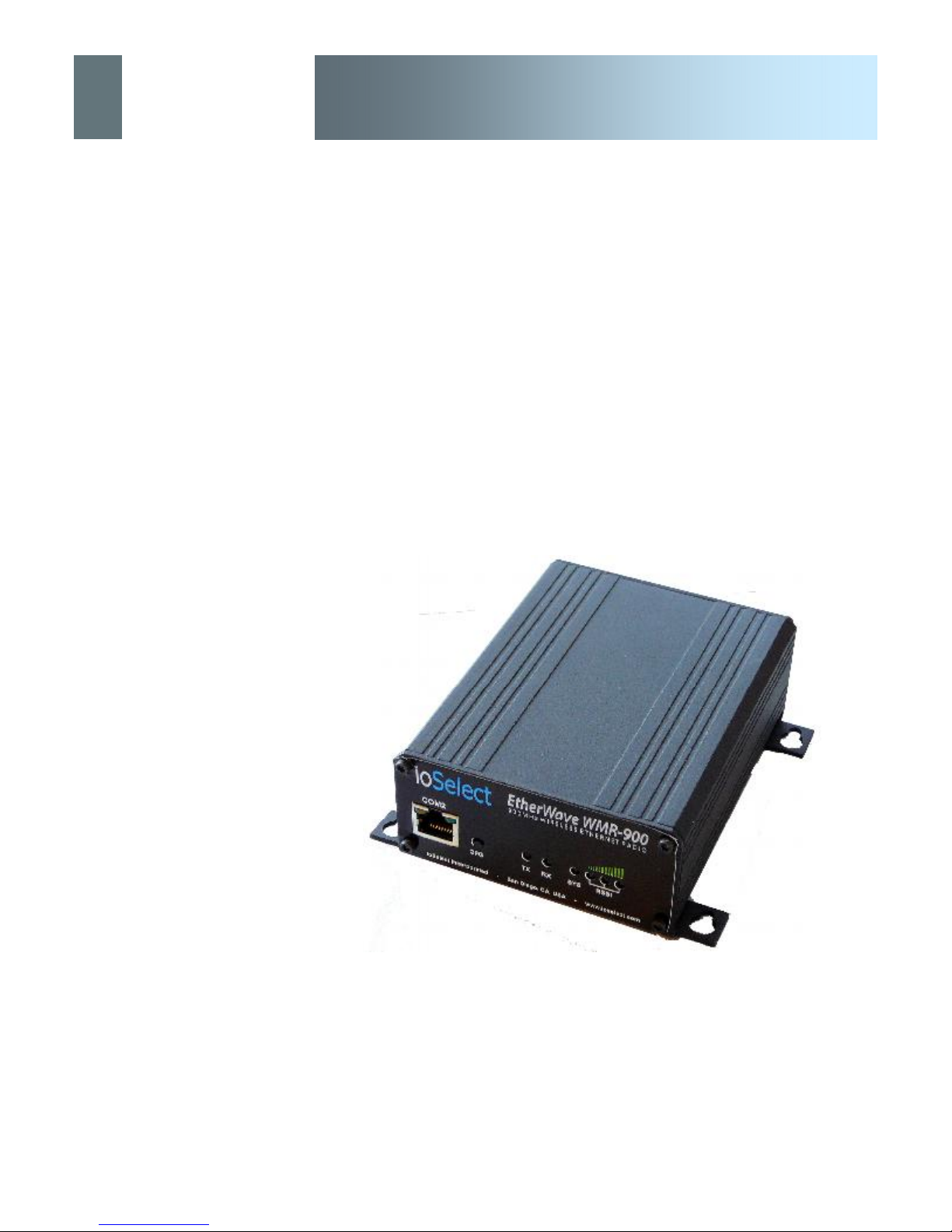
EtherWave - WMR
Operating Manual
EtherWave-WMR
900MHz Wireless Ethernet Bridge/Serial Gateway
Firmware Version 2.0.0
Document: EtherWave-WMR.OM.Rev3.1
April 14, 2008
© ioSelect Inc. CONFIDENTIAL
ioSelect
11440 West Bernardo Court
San Diego, CA 92127
Phone: (877) 343-8467
Fax: (877) 343-8467
www.ioselect.com
Page 2

ioSelect
ioSelect
Important User Information
Warranty
IoSelect Inc. warrants that each product will be free of defects in material and workmanship for a period of
one (1) year for its products. The warranty commences on the date the product is shipped by IoSelect Inc.
IoSelect Inc.’s sole liability and responsibility under this warranty is to repair or replace any product which is
returned to it by the Buyer and which IoSelect Inc. determines does not conform to the warranty. Product returned to IoSelect Inc. for warranty service will be shipped to IoSelect Inc. at Buyer’s expense and will be returned to Buyer at IoSelect Inc.’s expense. In no event shall IoSelect Inc. be responsible under this warranty
for any defect which is caused by negligence, misuse or mistreatment of a product or for any unit which has
been altered or modified in any way. The warranty of replacement shall terminate with the warranty of the
product.
Warranty Disclaims
IoSelect Inc. makes no warranties of any nature of kind, expressed or implied, with respect to the hardware,
software, and/or products and hereby disclaims any and all such warranties, including but not limited to warranty of non-infringement, implied warranties of merchantability for a particular purpose, any interruption or
loss of the hardware, software, and/or product, any delay in providing the hardware, software, and/or product
or correcting any defect in the hardware, software, and/or product, or any other warranty. The Purchaser
represents and warrants that IoSelect Inc. has not made any such warranties to the Purchaser or its agents
IOSELECT INC. EXPRESS WARRANTY TO BUYER CONSTITUTES IOSELECT INC. SOLE LIABILITY AND THE
BUYER’S SOLE REMEDIES. EXCEPT AS THUS PROVIDED, IOSELECT INC. DISCLAIMS ALL WARRANTIES, EXPRESS OR IMPLIED, INCLUDING ANY WARRANTY OF MERCHANTABILITY OR FITNESS FOR A PARTICULAR
PROMISE.
IOSELECT INC. PRODUCTS ARE NOT DESIGNED OR INTENDED TO BE USED IN ANY LIFE SUPPORT RELATED DEVICE OR SYSTEM RELATED FUNCTIONS NOR AS PART OF ANY OTHER
CRITICAL SYSTEM AND ARE GRANTED NO FUNCTIONAL WARRANTY.
Indemnification
The Purchaser shall indemnify IoSelect Inc. and its respective directors, officers, employees, successors and
assigns including any subsidiaries, related corporations, or affiliates, shall be released and discharged from
any and all manner of action, causes of action, liability, losses, damages, suits, dues, sums of money, expenses (including legal fees), general damages, special damages, including without limitation, claims for personal injuries, death or property damage related to the products sold hereunder, costs and demands of every
and any kind and nature whatsoever at law.
EtherWave - WMR
IN NO EVENT WILL IOSELECT INC. BE LIABLE FOR ANY INDIRECT, SPECIAL, CONSEQUENTIAL, INCIDENTAL,
BUSINESS INTERRUPTION, CATASTROPHIC, PUNITIVE OR OTHER DAMAGES WHICH MAY BE CLAIMED TO
ARISE IN CONNECTION WITH THE HARDWARE, REGARDLESS OF THE LEGAL THEORY BEHIND SUCH CLAIMS,
WHETHER IN TORT, CONTRACT OR UNDER ANY APPLICABLE STATUTORY OR REGULATORY LAWS, RULES,
REGULATIONS, EXECUTIVE OR ADMINISTRATIVE ORDERS OR DECLARATIONS OR OTHERWISE, EVEN IF IOSELECT INC. HAS BEEN ADVISED OR OTHERWISE HAS KNOWLEDGE OF THE POSSIBILITY OF SUCH DAMAGES
AND TAKES NO ACTION TO PREVENT OR MINIMIZE SUCH DAMAGES. IN THE EVENT THAT REGARDLESS OF
THE WARRANTY DISCLAIMERS AND HOLD HARMLESS PROVISIONS INCLUDED ABOVE IOSELECT INC. IS SOMEHOW HELD LIABLE OR RESPONSIBLE FOR ANY DAMAGE OR INJURY, IOSELECT INC.'S LIABILITY FOR ANYDAMAGES SHALL NOT EXCEED THE PROFIT REALIZED BY IOSELECT INC. ON THE SALE OR PROVISION OF THE
HARDWARE TO THE CUSTOMER.
Proprietary Rights
The Buyer hereby acknowledges that IoSelect Inc. has a proprietary interest and intellectual property rights in
the Hardware, Software and/or Products. The Purchaser shall not (i) remove any copyright, trade secret,
trademark or other evidence of IoSelect Inc.’s ownership or proprietary interest or confidentiality other proprietary notices contained on, or in, the Hardware, Software or Products, (ii) reproduce or modify any Hardware, Software or Products or make any copies thereof, (iii) reverse assemble, reverse engineer or decompile
any Software or copy thereof in whole or in part, (iv) sell, transfer or otherwise make available to others the
Hardware, Software, or Products or documentation thereof or any copy thereof, except in accordance with this
Agreement.
© ioSelect Inc. CONFIDENTIAL 2
Page 3
ioSelect
Important User Information (continued)
About This Manual
It is assumed that users of the products described herein have either system integration or
design experience, as well as an understanding of the fundamentals of radio communications.
Throughout this manual you will encounter not only illustrations (that further elaborate on the
accompanying text), but also several symbols which you should be attentive to:
Caution or Warning
Usually advises against some action which could result in undesired or
detrimental consequences.
EtherWave - WMR
Point to Remember
Highlights a key feature, point, or step which is noteworthy. Keeping
these in mind will simplify or enhance device usage.
Tip
An idea or suggestion to improve efficiency or enhance usefulness.
Information
Information regarding a particular technology or concept.
© ioSelect Inc. CONFIDENTIAL 3
Page 4
ioSelect
Important User Information (continued)
Regulatory Requirements
To satisfy FCC RF exposure requirements for mobile transmitting devices, a separation
distance of 23cm or more should be maintained between the antenna of this device and
persons during device operation. To ensure compliance, operations at closer than this
WARNING
WARNING
WARNING
distance is not recommended. The antenna being used for this transmitter must not be
co-located in conjunction with any other antenna or transmitter.
This device can only be used with Antennas listed in Appendix D. Please contact
IoSelect Inc. if you need more information or would like to order an antenna.
MAXIMUM EIRP
FCC Regulations allow up to 36dBm Effective Isotropic Radiated Power (EIRP).
Therefore, the sum of the transmitted power (in dBm), the cabling loss and the antenna
gain cannot exceed 36dBm.
EtherWave - WMR
EQUIPMENT LABELING
This device has been modularly approved. The manufacturer, product name, and FCC
and Industry Canada identifiers of this product must appear on the outside label of the
WARNING
SAMPLE LABEL REQUIREMENT:
For OEM Series For OEM Series
FCCID: NS906P21
IC: 3143A-06P21
This device complies with Part 15 of the FCC Rules.
Operation is subject to the following two conditions:
(1) this device may not cause harmful interference,
and (2) this device must accept any interference
received including interference that may cause
undesir ed operation.
Please Note: These are only sample labels; different products contain different identifiers. The
actual identifiers should be seen on your devices if applicable.
end-user equipment.
FCCID: NS905P20
IC: 3143A-05P20
This device complies with Part 15 of the FCC Rules.
Operation is subject to the following two conditions:
(1) this device may not cause harmful interference,
and (2) this device must accept any interference
received including interference that may cause
undesir ed operation.
© ioSelect Inc. CONFIDENTIAL 4
Page 5

ioSelect
EtherWave - WMR
CSA Class 1 Division 2 Option
CSA Class 1 Division 2 is Available Only on
Specifically Marked Units
If marked this for Class 1 Division 2 – then this product is available
for use in Class 1, Division 2, in the indicated Groups on the product.
In such a case the following must be met:
The transceiver is not acceptable as a stand-alone unit for use in
hazardous locations. The transceiver must be mounted within a
separate enclosure, which is suitable for the intended application.
Mounting the units within an approved enclosure that is certified for
hazardous locations, or is installed within guidelines in accordance
with CSA rules and local electrical and fire code, will ensure a safe
and compliant installation.
The antenna feed line; DC power cable and interface cable must be
routed through conduit in accordance with the National Electrical
Code.
Do not connect or disconnect equipment unless power has been
switched off or the area is known to be non-hazardous.
Installation, operation and maintenance of the transceiver should be
in accordance with the transceiver’s installation manual, and the
National Electrical Code.
Tampering or replacement with non-factory components may
adversely affect the safe use of the transceiver in hazardous
locations, and may void the approval.
The wall adapters supplied with your transceivers are NOT Class 1
Division 2 approved, and therefore, power must be supplied to the
units using the screw-type or locking type connectors supplied from
IoSelect Inc. and a Class 1 Division 2 power source within your
panel.
If you are unsure as to the specific wiring and installation guidelines
for Class 1 Division 2 codes, contact CSA International.
© ioSelect Inc. CONFIDENTIAL 5
Page 6

ioSelect
Revision History
Revision 3.1 April 01, 2008
Based on: Ref. 6.1.2 FPGA Version 1R4, Software Version 2.0.0; Ref. 6.1.8/Radio Info. Version 3.1092ip
Updated formatting, added Appendix C.
EtherWave - WMR
© ioSelect Inc. CONFIDENTIAL 6
Page 7

ioSelect
Table of Contents
1.0 Overview ....................................................................................10
1.1 Performance Features 12
1.2 Specifications 12
2.0 QUICK START ...........................................................................13
2.1 Factory Default/Reset Method 13
2.2 Text User Interface Method 15
2.21 Required Materials 15
2.22 Set-Up Procedure 15
3.0 Hardware Features ...................................................................19
3.1 Connections 19
3.1.1 Front 19
3.1.2 Rear 21
3.2 Indicators 23
3.2.1 Front 23
3.2.2 Rear 24
EtherWave - WMR
4.0 Operating Modes ...................................................................... 25
4.1 Master 25
4.2 Repeater 25
4.3 Remote 25
5.0 Network Topologies ................................................................. 26
Note: This section includes examples of configurations for each of the
following:
5.1 Point-to-Point (PTP) 26
5.2 Point-to-Multipoint (PMP) 28
5.3 Peer-to-Peer (P2P) 31
5.4 Everyone-to-Everyone (E2E) 33
6.0 Configuration ............................................................................35
6.1 Web User Interface 36
6.1.1 Logon Window 37
6.1.2 Welcome Window 39
6.1.3 System Configuration 40
6.1.4 Network Configuration ................................................................. 43
6.1.4.1 Local IP Configuration 44
6.1.4.1.1 Bridge 44
6.1.4.1.2 Router 48
6.1.4.1.2.1 Wireless Port IP Configuration 49
6.1.4.1.2.2 VPN Configuration 51
6.1.4.2 NTP Server Configuration 53
© ioSelect Inc. CONFIDENTIAL 7
continued...
Page 8

ioSelect
Table of Contents (continued)
6.1.4.3 DHCP Server Configuration 55
6.1.4.3.1 Bridge 55
6.1.4.3.2 Router 55
6.1.4.4 SNMP Agent Configuration 61
6.1.4.5 Bridge Configuration 67
6.1.4.6 Quality of Service 68
6.1.5 Radio Configuration 71
6.1.6 COM1 and COM2 Configuration 89
6.1.7 Security Configuration ...................................... ........................101
6.1.7.1 Admin Password Configuration 102
6.1.7.2 Upgrade Password Configuration 103
6.1.7.3 Wireless Encryption Configuration 104
6.1.7.4 Discovery Service Configuration 108
6.1.7.5 UI (User Interface) Access Configuration 110
6.1.7.6 Authentication Configuration 112
6.1.7.7 Firewall Configuration 115
6.1.7.7.1 Policies 116
6.1.7.7.2 Rules 119
6.1.7.7.3 Port Forwarding 123
6.1.7.7.4 MAC List 125
6.1.7.7.5 Blacklist 127
6.1.7.7.6 Reset Firewall to Factory Default 129
6.1.8 System Information 131
6.1.9 System Tools ........................................................................... 137
6.1.9.1 System Maintenance 138
6.1.9.2 Reboot System 139
6.1.9.3 Reset System to Default 140
6.1.9.4 Radio Channels Noise Level 141
6.1.9.5 Network Discovery 143
6.1.9.6 Logout 144
6.2 Text User Interface 145
EtherWave - WMR
7.0 Installation ............................................................................... 149
7.1 Path Calculation 152
7.2 Installation of Antenna System Components 153
7.2.1 Antennas 154
7.2.2 Coaxial Cable 155
7.2.3 Surge Arrestors 155
7.2.4 External Filter 156
© ioSelect Inc. CONFIDENTIAL 8
Page 9

ioSelect
Table of Contents (continued)
Appendices
Appendix A: RS485 Wiring 157
Appendix B: Mounting Dimensions 158
Appendix C: Serial Interface 159
EtherWave - WMR
© ioSelect Inc. CONFIDENTIAL 9
Page 10

ioSelect
1.0 Overview
EtherWave - WMR
The EtherWave-WMR is a high-performance wireless ethernet bridge
and serial gateway. Alternately, a Master EtherWave-WMR unit may
be configured to operate as a wireless ethernet router (and serial
gateway).
A BRIDGE separates two network
segments within the same logical
network (subnet).
A ROUTER forwards data across
internetworks (different subnets).
A SERIAL GATEWAY allows
asynchronous serial data to enter
(as through a gate) the realm of IP
communications.
The serial data is encapsulated
within UDP or TCP packets.
When properly configured and installed, long range communications
at very high speeds can be achieved.
The EtherWave-WMR operates within the 902-928MHz ISM frequency band, employing frequency hopping spread spectrum
(FHSS) and also, for 1.1Mbps operation, digital transmission service
(DTS) technology.
They provide reliable wireless ethernet bridge functionality as well
gateway service for asynchronous data transfer between most equipment types which employ an RS232, RS422, or RS485 interface.
· SCADA
· remote telemetry
· traffic control
· industrial controls
· remote monitoring
· LAN extension
The small size and superior performance of the EtherWave-WMR
makes it ideal for many applications. Some typical uses for this modem:
· GPS
· wireless video
· robotics
· display signs
· fleet management
1.1 Performance Features
© ioSelect Inc. CONFIDENTIAL 10
Key performance features of the EtherWave-WMR include:
· transmission within a public, license-exempt band of the radio
spectrum1 - this means that the modems may be used without
access fees or recurring charges (such as those incurred by
cellular airtime)
· maximum allowable transmit power (1 Watt)
· longest range
· transparent, low latency link providing reliable wireless IP/
ethernet communications with constant baud rate over
distance
1 920-928MHz, which is license-exempt within North America, may need to be
factory-c onfigured differently for other areas: contact IoSelect Inc.
Page 11

ioSelect
1.0 Overview
EtherWave - WMR
· each unit supports all modes of operation (Master, Repeater,
Remote)
· Repeater may also be used concurrently as a Remote unit
· flexible wireless networking: point-to-point, point-to-multipoint,
peer-to-peer, store and forward repeater
· communicates with virtually all PLCs, RTUs, and serial devices
through either one of two available RS232 interface, RS422, or
RS485
· fastest serial rates: 300 baud to 921kbps
· advanced serial port supports legacy serial devices, including
RTS, CTS, DSR, DTR, and DCD.
· Easy to manage through web- or text-based user interface, or
SNMP
· wireless firmware upgrades
· system wide remote diagnostics
· 32-bit CRC, selectable retransmission
· advanced security features
· industrial temperature specifications
· DIN rail mountable
· Optional Class 1 Div 2
· Available as OEM solution
Supporting co-located independent networks and with the ability to
carry both serial and IP traffic, the EtherWave-WMR supports not
only network growth, but also provides the opportunity to migrate
from asynchronous serial devices connected today to IP-based devices in the future.
© ioSelect Inc. CONFIDENTIAL 11
Page 12

ioSelect
1.0 Overview
EtherWave - WMR
1.2 Specifications
Refer to the Specifications Sheet supplied to you for your particular model.
© ioSelect Inc. CONFIDENTIAL 12
Page 13
ioSelect
2.0 Quick Start
EtherWave - WMR
This QUICK START guide will enable you to promptly establish basic
IP connectivity between a pair of EtherWave-WMR in a point-to-point
(ref. 5.1) configuration.
Note that the units arrive from the factory with a Radio Configuration
of ‘Remote’ and the Local Network setting configured as ‘Static’ (IP
Address 192.168.1.254, Subnet Mask 255.255.255.0, and Gateway
192.168.1.1).
2.1 Factory Default/Reset Method
2.11 Required Materials
· 2 EtherWave-WMR (with (or set to) factory default
configuration), each with Power Adapter and Rubber
Ducky Antenna
· 1 PC with NIC (ethernet) card
· 1 Crossover patchcable (ethernet)*
Use the supplied power adapter or
an equivalent power source.
To ensure that the EtherWaveWMR unit is at its DEFAULT
factory settings, once it has
powered-up and the SYS LED is
ON (after 1 minute), press and
hold the front CFG button for 8
seconds - the SYS LED will initially
blink, then be on solid, and then
the unit will reset.
Note: Some OEM customers will
have their specific factory defaults
loaded.
*dependent on desired test set-up
2.12 Set-Up Procedure
· Connect a Rubber Ducky antenna to each EtherWaveWMR.
· Connect the Power Adapters to available 120VAC outlets, and to the EtherWave-WMR. The SYS LED will
blink for approximately 1 minute while it readies itself for
operation.
· Using CROSSOVER ethernet patchcable, connect PC
NIC card to rear ETHERNET connection on EtherWaveWMR. (PC must have its Network Settings (TCP/IP
Properties) set to STATIC with an IP Address of (e.g.)
192.168.1.10 and a Subnet Mask of 255.255.255.0.)
· Open a Web Browser and enter the IP Address
(192.168.1.254) of the EtherWave-WMR into the URL
address line.
· Refer to Section 6.1.1 re LogOn.
© ioSelect Inc. CONFIDENTIAL 13
Page 14

ioSelect
2.0 Quick Start
EtherWave - WMR
· Refer to Section 6.1.4.1 re Network (IP) Configuration
and assign the unit a new unique IP Address.
· Refer to Section 5.1 and, as per the example settings
given, configure unit as MASTER.
· Repeat the above for the other EtherWave-WMR, giving
it a new unique IP Address and configuring it as a REMOTE (5.1).
· With both units powered-on, in proximity to each other,
and configured as per the above, their RSSI LEDs
should be illuminated, and their TX LED should be ON or
flashing.
· With the PC connected to one of the EtherWave-WMR
units, enter the IP Address of ‘the other’ unit: its LogOn
window should appear via the wireless connection.
.
© ioSelect Inc. CONFIDENTIAL 14
Page 15

ioSelect
2.0 Quick Start
EtherWave - WMR
2.2 Text UI Method
(See Section 6.2 for more information re the Text User Interface.)
2.21 Required Materials
· 2 EtherWave-WMR (with factory default configuration),
each with Power Adapter and Rubber Ducky An
tenna
· 1 PC with NIC (ethernet) card and COM (serial) port
with HyperTerminal (or equivalent) application
· 1 Available connection to LAN*
· 1 Crossover patchcable (ethernet)*
· 1 Diagnostic Cable
*dependent on desired test set-up
Use the supplied power adapter or
an equivalent power source.
2.22 Set-Up Procedure
· Connect a Rubber Ducky antenna to each EtherWaveWMR.
· Connect the Power Adapters to available 120VAC outlets, and to the EtherWave-WMR.
· Connect the Diagnostic Cable to COM2 (front) of one
EtherWave-WMR and the other end to an available COM
port on the PC.
· Run HyperTerminal (or equivalent terminal program) on
the PC and configure it for the COM port chosen above,
115200bps, 8 data bits, no parity, 1 stop bit, and no flow
control.
· Activate the HyperTerminal connection.
· A login prompt will appear. Enter admin.
· At the password prompt, enter admin.
© ioSelect Inc. CONFIDENTIAL 15
Page 16

ioSelect
2.0 Quick Start
View the PC’s NETWORK
SETTINGS (TCP/IP Properties) to
determine an appropriate IP
Address, Subnet Mask, and
Gateway for the EtherWave-WMR.
(For basic testing, the Gateway
value is not critical.)
If a connection is being made to a
network (LAN), check with the
Network Administrator for an
available static IP address(es) so
as not to potentially create an IP
address conflict.
EtherWave - WMR
· Select Option B: Network Configuration, then
· A: Local IP Config, then
· A: IP Address Mode, then
· A: static
· Input suitable (for your PC/network) values for:
· IP Address
· Subnet Mask
· Gateway
· Press U to SAVE the configuration changes.
· Press [Esc] twice to return to the MAIN MENU.
· Select Option C: Radio Configuration, then
· B: Operation Mode, then
· A: Master, then
· I: Network Type, then
· B: Point-to-Point, then
· J: Destination Unit, then
enter the number 20 [Enter]
© ioSelect Inc. CONFIDENTIAL 16
· Press U to SAVE the configuration changes.
· Press [Esc] to return to the MAIN MENU.
· Press Q to Quit.
The EtherWave-WMR configured above is now the MASTER EtherWave-WMR for your Point-to-Point EtherWave-WMR network.
Remove the connection from the MASTER EtherWave-WMR’s
COM2 port and move it to the other EtherWave-WMR.
· Press [Enter]
· A login prompt will appear. Enter admin.
· At the password prompt, enter admin.
continued...
Page 17

ioSelect
2.0 Quick Start
EtherWave - WMR
· Select Option B: Network Configuration, then
· A: Local IP Config, then
· A: IP Address Mode, then
· A: static
· Input suitable (for your PC/network) values for:
· IP Address
· Subnet Mask
· Gateway
· Press U to SAVE the configuration changes.
· Press [Esc] twice to return to the MAIN MENU.
· Select Option C: Radio Configuration, then
· B: Operation Mode, then
· C: Remote, then
· F: Unit Address, then
· enter the number 20 [Enter]
· I: Network Type, then
· B: Point-to-Point, then
· J: Destination Unit, then
enter the number 1 [Enter]
· Press U to SAVE the configuration changes.
· Press [Esc] to return to the MAIN MENU.
· Press Q to Quit.
The EtherWave-WMR configured above is now the REMOTE EtherWave-WMR for your Point-to-Point EtherWave-WMR network.
With these two EtherWave-WMR on a test bench, and configured as
per the preceding, a wireless link will be present between the two
units. This may be confirmed by noting that the RSSI (3 front panel
LEDs) are illuminated.
© ioSelect Inc. CONFIDENTIAL 17
Next, the ethernet connections will be made.
continued...
Page 18

ioSelect
2.0 Quick Start
To connect an EtherWave-WMR to
a PC, an ethernet CROSSOVER
(not a straight-through) cable must
be used.
EtherWave - WMR
The ethernet connections are dependent upon what is available to
work with for the test configuration. For the purposes of this QUICK
START, the assumption is that a LAN connection is available (with
Internet connectivity) and that the PC is connected to this LAN.
· Disconnect the PC’s LAN connection from its NIC card
and insert the now ‘loose end’ of the ethernet patchcable
into the rear ETHERNET RJ45 connector at the rear of
the MASTER EtherWave-WMR.
· Using a CROSSOVER cable, connect the PC’s NIC card
RJ45 jack to the ETHERNET RJ45 connector on the REMOTE EtherWave-WMR.
At this point there is a wireless connection between the PC and the
LAN, and you should be able to go about your typical networking activities, including accessing the Internet (via the LAN).
Also, by opening a web browser and entering the IP address of either
EtherWave-WMR, you will be taken to the respective unit’s Web User
Interface LOGIN window.
If communications not available as outlined above:
· Verify the RSSI LEDs on the front of each EtherWaveWMR are illuminated.
· Verify TX (red) LED activity on the front of each EtherWave-WMR.
· Observe the rear of each EtherWave-WMR, specifically
the ETHERNET connection: the green LINK LED should
be illuminated (indicating proper cabling) and the amber
(ACTIVITY LED) should also be flickering—indicating
DATA traffic at the ETHERNET connector.
· If using Windows XP, the firewall function could inhibit
desired data traffic. Anti-virus software may also have a
negative impact.
© ioSelect Inc. CONFIDENTIAL 18
Page 19
ioSelect
3.0 Hardware Features
EtherWave - WMR
The EtherWave-WMR is a fully-enclosed unit ready to be interfaced
to external devices.
Any EtherWave-WMR may be configured as a Master, Repeater (or
Repeater/Slave), or Slave. This versatility is very convenient from a
’sparing’ perspectiv e, as well for convenience in becoming very
familiar and proficient with using the device: if you are familiar with
one unit, you will be familiar with all units.
3.1 Connections
3.1.1 Front
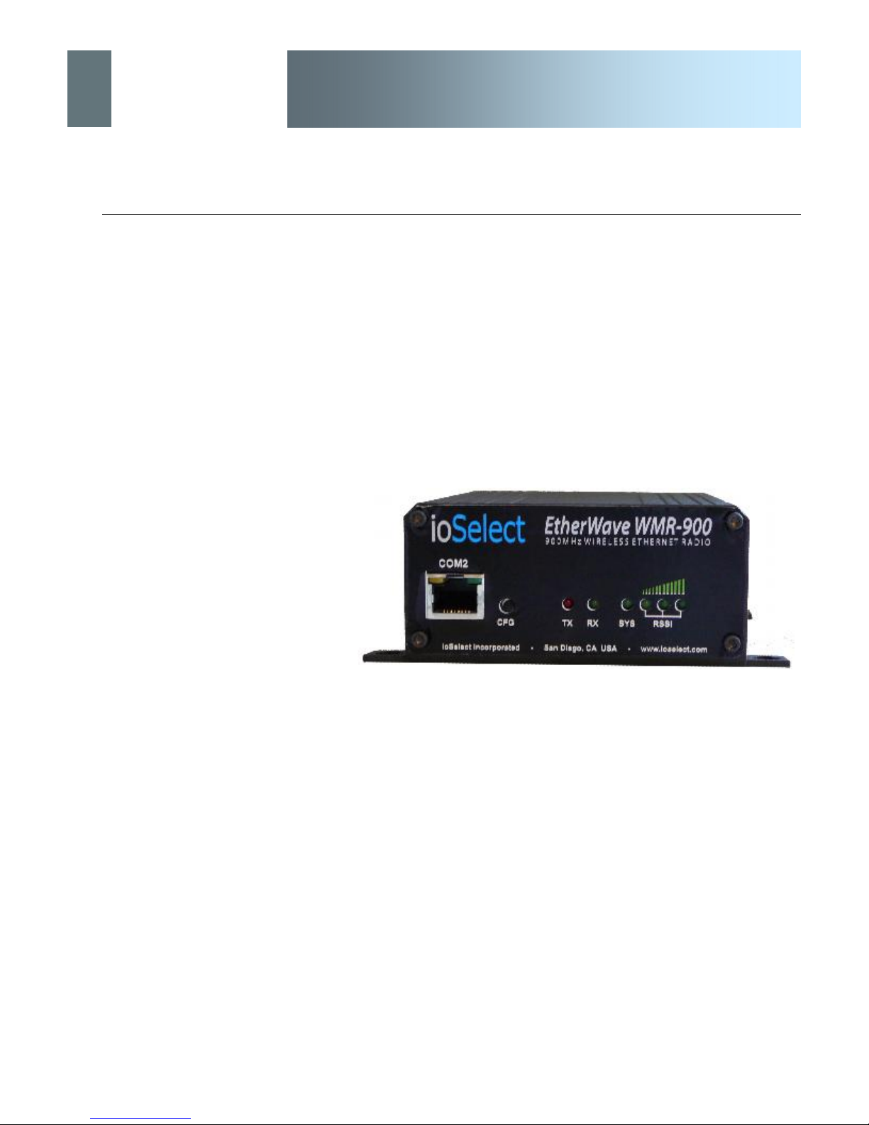
Image 3A: Front View of EtherWave-WMR
On the front of the EtherWave-WMR are, from left to right:
· COM2 Port (DCE)
· CFG pushbutton
· TX LED
· RX LED
· SYS LED
· RSSI LEDs (3)
© ioSelect Inc. CONFIDENTIAL 19
Page 20
ioSelect
3.0 Hardware Features
The COM2 port is NOT an
Ethernet port.
EtherWave - WMR
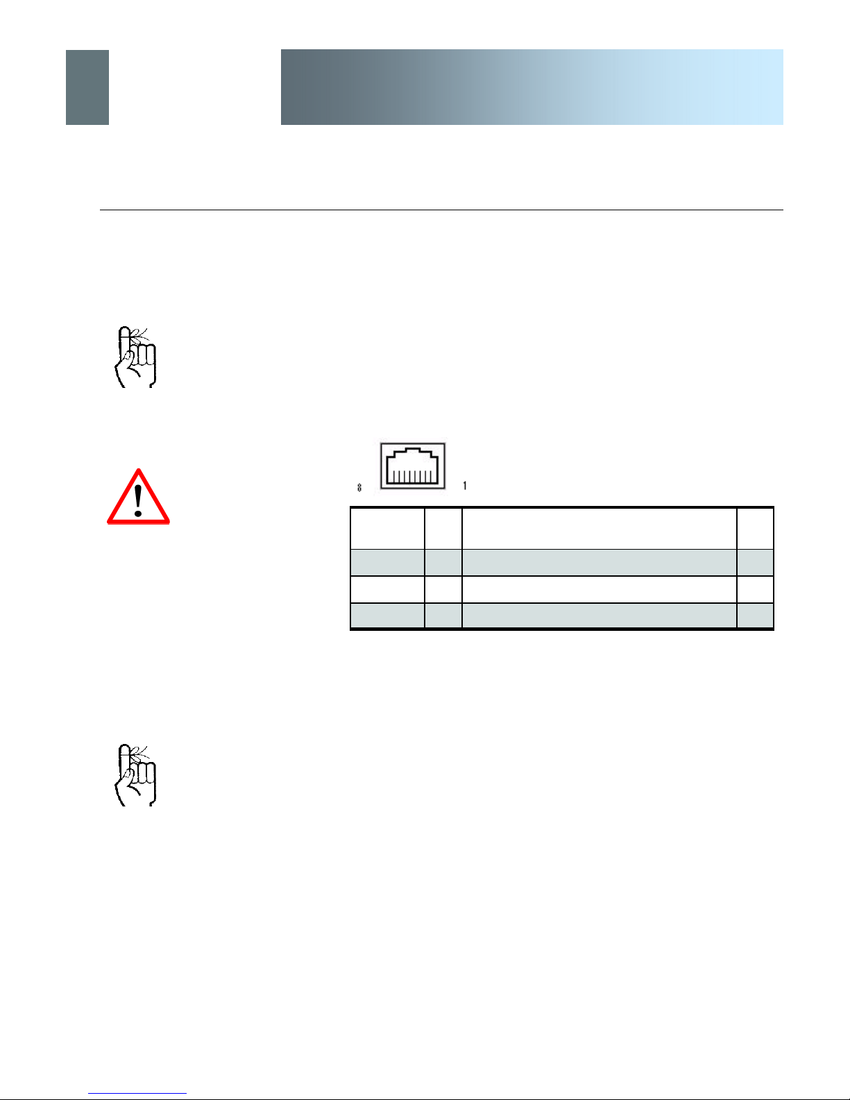
The COM2 Port (DCE) is used for two purposes:
· Text User Interface (local console port) at 115.2kbps
(using supplied BLACK RJ45-DE9 cable and
HyperTerminal (or equivalent).
· User data (serial, RS-232, wired for RxD, TxD, and SG)
DO NOT connect to COM2
pins other than those
identified in Table 3A, and for
their described function.
The CFG button (and ’default’
IP address 192.168.1.39) are
ONLY used for the purpose of
upgrading firmware.
The ’default’ IP address is
NOT available for accessing
the Web User Interface.
Pin Name No. Description In/
Out
RxD 2 Receiv e Data O
TxD 3 Transmit Data I
SG 5 Signal Ground
Table 3A: COM2 Pin Description
CFG Button
Holding this button depressed while powering-up the EtherWaveWMR will boot the unit into FLASH FILE SYSTEM RECOVERY
mode. The default IP address for system recovery (only - not for
normal access to the unit) is static: 192.168.1.39.
(For more information on performing a firmware upgrade, see
Appendix B and Section 6.1.9.1.)
If the unit has been powered-up for some time (>1 minute),
depressing the CFG Button for 8 seconds will result in FACTORY
DEFAULTS being restored, including a static IP address of
192.168.1.254. This IP address is useable in a Web Browser for
accessing the Web User Interface.
© ioSelect Inc. CONFIDENTIAL 20
Page 21
ioSelect
3.0 Hardware Features
EtherWave - WMR
3.1.2 Rear
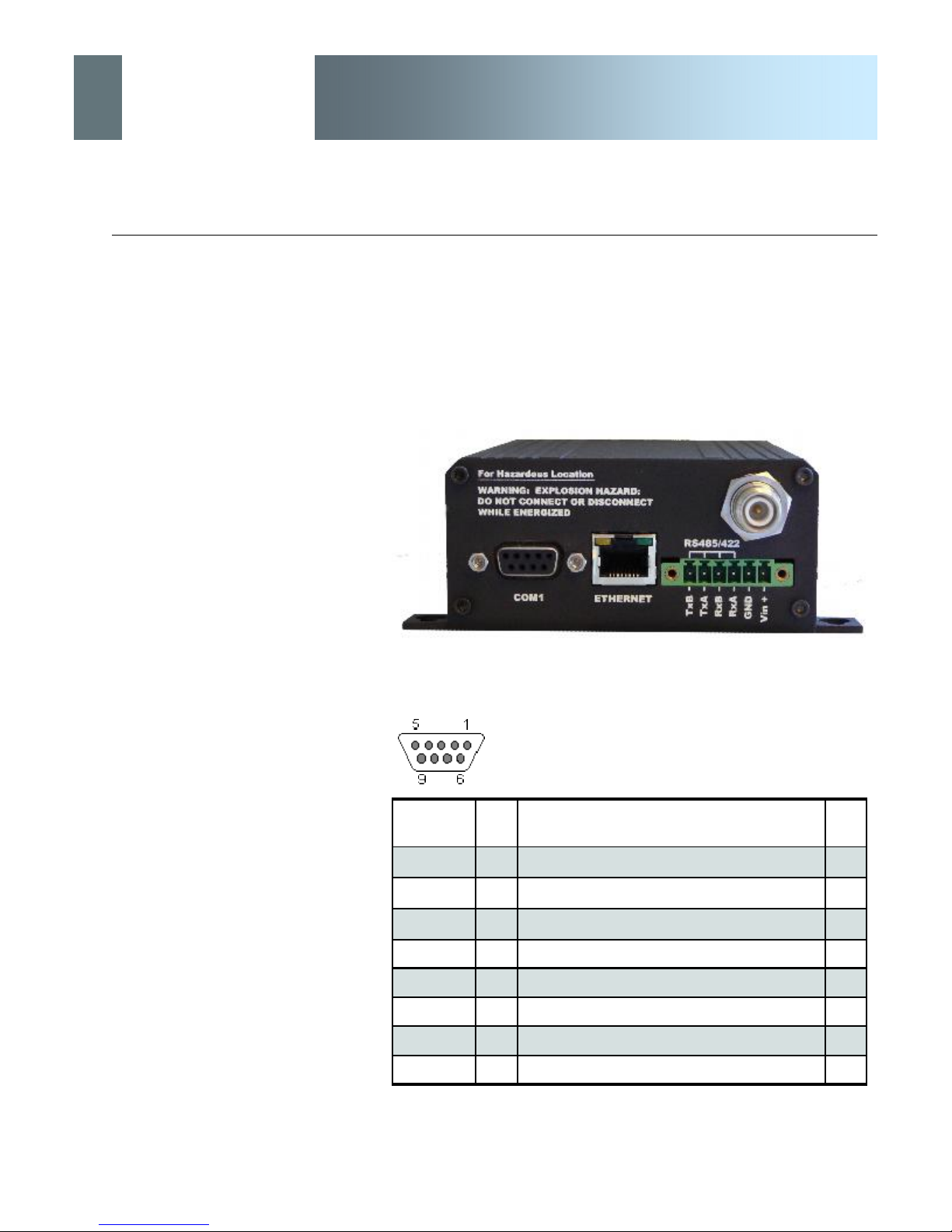
COM1 Port (DCE) on the rear of the EtherWave-WMR is used for
RS232 serial data (300 baud to 230.4kbps) communications.
RS422/485 Port used to interface the EtherWave-WMR to a DTE
with the same interface type (300 baud to 921kbps).
Either the RS232 or RS422/485 interface is used for ‘COM1’ data
traffic.
Image 3B: Rear View of EtherWave-WMR
See Appendix F for a full description of the COM1
RS-232 interface functions.
Pin Name No. Description In/
Out
DCD 1 Data Carrier Detect O
RXD 2 Receive Data O
TXD 3 Transmit Data I
DTR 4 Data Terminal Ready I
SG 5 Signal Ground
DSR 6 Data Set Ready O
RTS 7 Request To Send I
CTS 8 Clear To Send O
Table 3B: COM1 (RS-232) Pin Assignment
© ioSelect Inc. CONFIDENTIAL 21
Page 22
ioSelect
3.0 Hardware Features
Caution: Using a power
supply that does not provide
proper voltage may damage
the EtherWave-WMR.
EtherWave - WMR
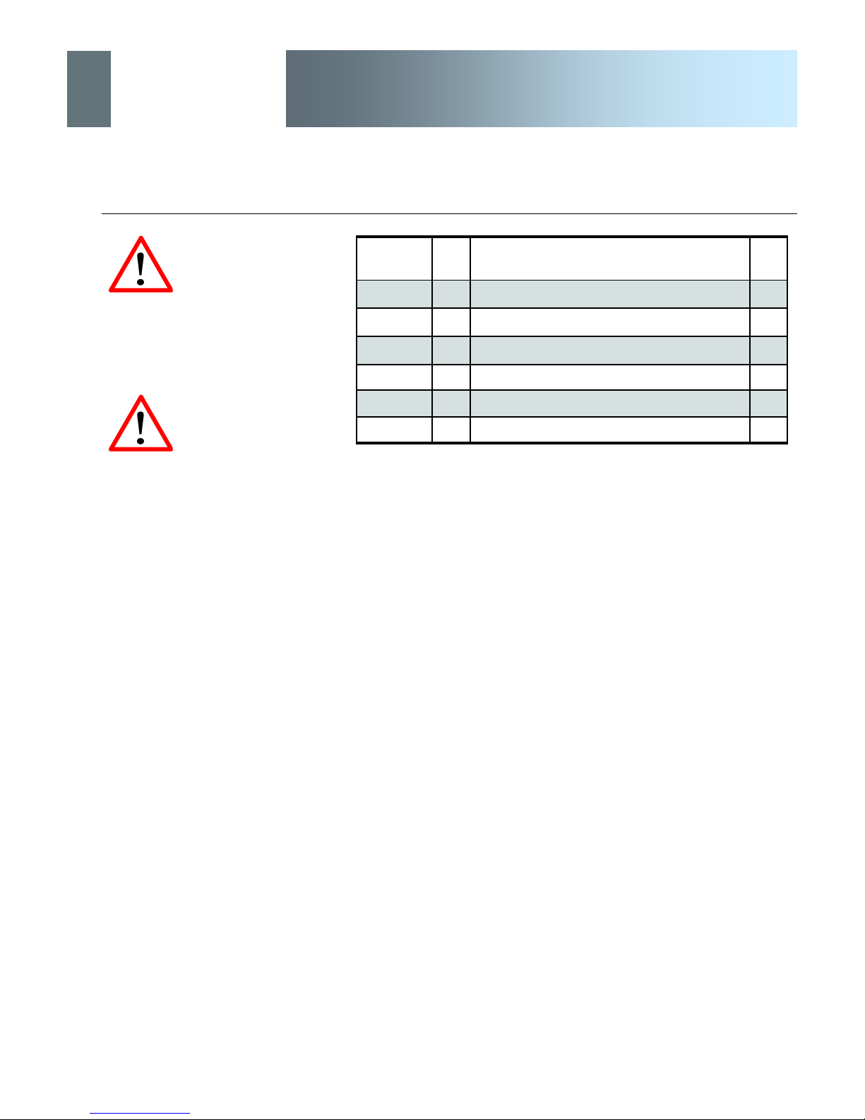
Pin Name No. Description In/
Out
TxB (D+) 1 Non-Inverting Driver Output O
TxA (D-) 2 Inverting Driver Output O
RxB (R+) 3 Non-Inverting Driver Input I
RxA (R-) 4 Inverting Driver Input I
GND 5 Ground (Power and Signal)
Vin+ 6 Positive Voltage Supply Input (12-30VDC) I
Caution: DO NOT connect
POWER to the DATA
SIGNAL pins of the Phoenixtype connector.
Table 3C: Phoenix-type Connector Pin Assignment
Antenna Connector
The EtherWave-WMR uses a reverse polarity TNC (RP-TNC)
connector. IoSelect Inc. can provide external cabling and
antennas suited to a variety of applications where the standard
rubber ducky antenna is not adequate.
© ioSelect Inc. CONFIDENTIAL 22
Page 23
ioSelect
3.0 Hardware Features
EtherWave - WMR
3.2 Indicators
3.2.1 Front
Alarm LED (Amber)
Located at top/left of COM2 port, illuminates when there is a load/
transmitter impedance mismatch—indicating a possible problem in
the antenna system.
MHX Status LED (Green)
Located at top/right of COM2 port, illuminates when the MHX core
module is powered-up and okay.
TX LED
DO NOT cycle power during
DO NOT cycle power during
the ‘Upgrading’ process:
the ‘Upgrading’ process:
doing so will corrupt the flash
doing so will corrupt the flash
file system and the
file system and the
EtherWave-WMR will not boot
EtherWave-WMR will not boot
properly. If this occurs, the
properly. If this occurs, the
system can only be restored
system can only be restored
using the recovery procedure.
using the recovery procedure.
The transmit (TX) LED is illuminated when the EtherWave-WMR is
transmitting data wirelessly.
RX LED
This LED, when illuminated, indicates that the modem is
synchronized and/or receiving valid packets of data.
SYS LED
The System Status LED operation is described in the following
table:
System Mode SYS LED Status
Normal On
Recovery Fast Blink (3 per second)
Loading (e.g. on normal power-up) Slow Blink (1 every 2 seconds)
Upgrading Slow Blink (1 every 2 seconds)
Table 3D: SYS LED Operation
Upon initial application of power the SYS LED will be illuminated for
approximately 20 seconds, after which time it will being to blink
slowly (loading) for an additional 25 seconds, then stay ON
‘solid’ (indicating it has achieved its specific operational status).
© ioSelect Inc. CONFIDENTIAL 23
Page 24

ioSelect
3.0 Hardware Features
EtherWave - WMR
Receive Signal Strength Indicator (RSSI) (3x Green) LEDs
As the received signal strength increases, so does the number of
illuminated RSSI LEDs, starting with the furthest left. RSSI is
calculated based on the last four valid recieved packets. For robust
wireless communications performance, strive for a minimum of 2
RSSI LEDs being lit.
Initially, a remote unit’s RSSI LED’s will ‘scan’ (cycle from right to
left, each LED being on for 300ms in turn). Once the unit acquires
synchronization with the network, a ‘steady’ RSSI reading will be
displayed.
A Master updates its RSSI indication upon receiving valid packets
from remote units. It takes into consideration packets received from
both Repeaters and Remotes.
When initially cabling between
devices, pay close attention to
the Activity LED to confirm that
proper patchcable types are
being used.
A Repeater will base its RSSI reading on valid packets received
from Slaves; if the Slaves are silent for 2 seconds, the Repeater will
display an RSSI value based on valid packets received from the
Master.
Signal strength is calculated based on the last four valid received
packets with correct CRC.
3.2.2 Rear
Collision LED (Amber)
Located at top/left of the ETHERNET connector, illuminates when
there is a collision on the ethernet interface.
Activity LED (Green)
Located at top/right of the ETHERNET connector, illuminates when
there is data activity present on the ethernet interface.
© ioSelect Inc. CONFIDENTIAL 24
Page 25

ioSelect
4.0 Operating Modes
EtherWave - WMR
An EtherWave-WMR may be configured for any operating mode:
this is very convenient for purposes of sparing and becoming familiar
with their configuration menus.
4.1 Master
One per network, the source of synchronization for the system. The
Master controls the flow of data through the system.
4.2 Repeater
Required only if necessary to establish a radio path between a Master and Remote(s); stores and forwards the data sent to it. Synchronizes to Master and provides synchronization to ‘downstream’ units.
If a local device is attached to a Repeater’s serial data port, the Repeater will also behave as a Remote (aka Repeater/Remote).
Throughout this manual,
‘Remote’ refers to a Remote
as defined in Section 4.4; the
general term ‘remote’ applies
to an EtherWave-WMR
Repeater and/or Remote - i.e.
As they are added to a radio network it is good practice to use the
values 2-17, sequentially, for Repeater Unit Addresses.
Adding one or more Repeaters within a network will HALVE the
throughput; the throughput is halved only once, i.e. it does not decrease with the addition of more Repeaters.
If there is a ‘radio (signal) path’ requirement to provide Repeater
functionality, but throughput is critical, the repeating function may be
accomplished by placing two EtherWave-WMR at the Repeater site
in a ‘back-to-back’ configuration. One EtherWave-WMR would be
configured as a Remote in the ‘upstream’ network; the other a Master in the ‘downstream’ network. Local connection between the modems would be accomplished with a crossover cable (for the
ethernet connection). Each modem would require its own antenna;
careful consideration should be given with respect to antenna placement and EtherWave-WMR configuration.
4.3 Remote
Endpoint/node within a network to which a local device is attached.
Communicates with Master either directly or through one or more
Repeaters. See Sections 5.3 and 5.4 for information regarding
‘Slave-to-Slave’ communications.
© ioSelect Inc. CONFIDENTIAL 25
Page 26

ioSelect
5.0 Network Topologies
EtherWave - WMR
The EtherWave-WMR may be configured to operate in a number of
different operating modes and participate in various network topologies.
The RADIO network topology
determines the paths
available for the movement of
data.
Take this important fact into
consideration when selecting
a network topology.
Note: This section describes radio network topologies in general
and includes examples of corresponding Radio Configuration settings. Refer to section 6 for further detailed information regarding
configuration options.
5.1 Point-to-Point (PTP)
In a Point-to-Point network, a path is created to transfer data between Point A and Point B, where Point A may be considered the
Master modem and Point B a Remote. Such a PTP network may
also involve one or more Repeaters (in a store-and-forward capacity) should the radio signal path dictate such a requirement. (Note
that a Repeater may also concurrently function as a Remote, i.e. it
may pass data to and from an attached device(s).)
A PTP configuration may also be used in a more dynamic sense:
there may be many Remotes (and Repeaters) within such a network, however the Master may have its ‘Destination Address’
changed as and when required to communicate with a specific remote unit.
© ioSelect Inc. CONFIDENTIAL 26
An example of a basic PTP network consisting of two EtherWaveWMR is on the next page.
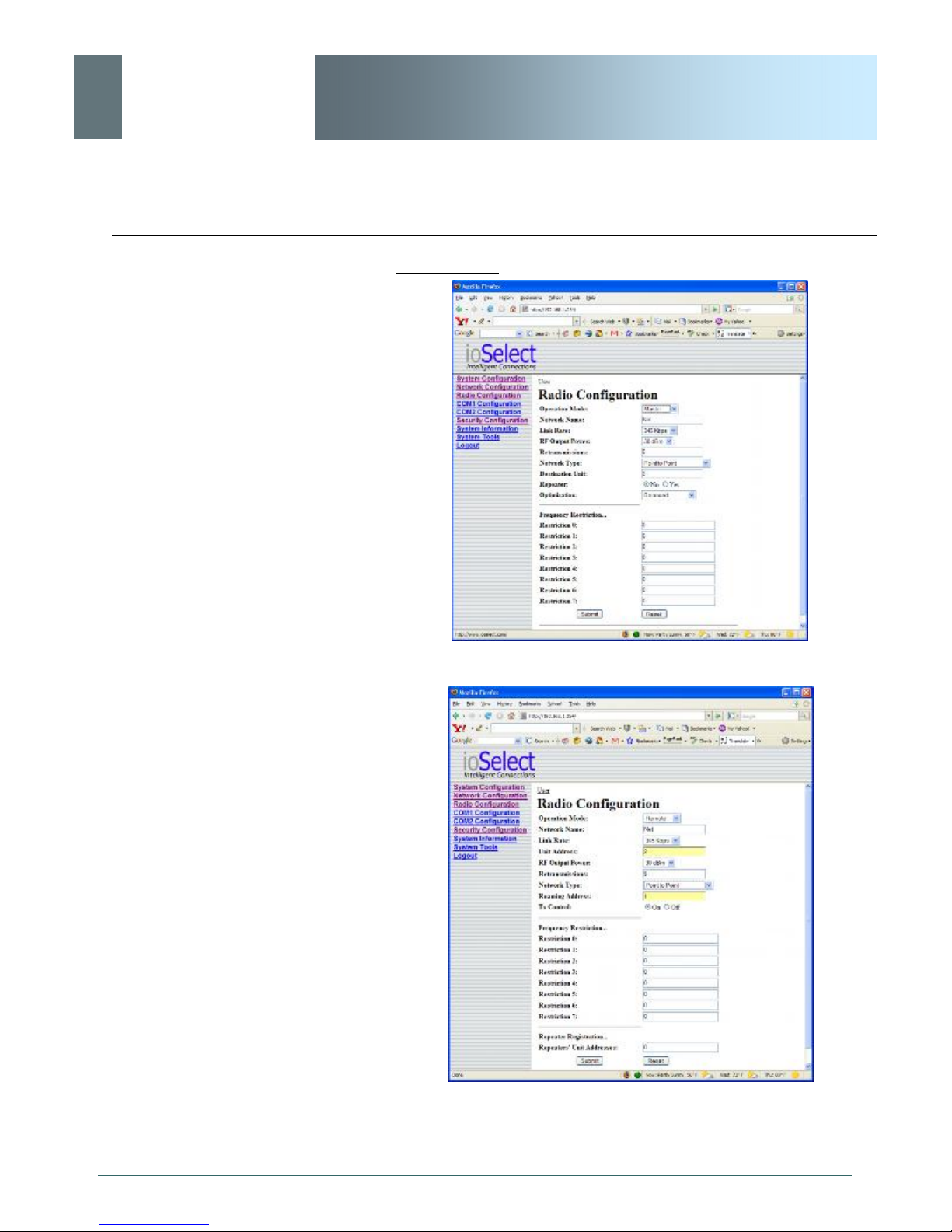
Notes re Example 5.1.1:
· Configuration options are based upon the chosen Operating Mode of the unit: select the Operating Mode
first.
· The DESTINATION UNIT for the MASTER is the UNIT
ADDRESS of the REMOTE, and vice versa (noting that
the MASTER’s Unit Address (not visible) is preset, and
must remain as, ‘1’).
· For a PTP system, RETRANSMISSIONS on a MAS-
TER is not as critical a setting as it is in a Point-toMultipoint (PMP) system.
Page 27
ioSelect
5.0 Network Topologies
EtherWave - WMR
Example 5.1.1
Image 5A: PTP Example 5.1.1: Master
Image 5B: PTP Example 5.1.1: Remote
© ioSelect Inc. CONFIDENTIAL 27
Page 28
ioSelect
5.0 Network Topologies
EtherWave - WMR
5.2 Point-to-Multipoint (PMP)
In a Point-to-Multipoint network, a path is created to transfer data
between the Master modem and numerous remote modems. The
remote modems may simply be Remotes with which the Master
communicates directly, and/or Remotes which communicate via
Repeaters. Some or all of the Repeaters may also act as Remotes
in this type of Network, i.e. the Repeaters are not only storing and
forwarding data, but are also acting as Remotes. Such Repeaters
may be referred to as ‘Repeater/Remotes’.
Example 5.2.1
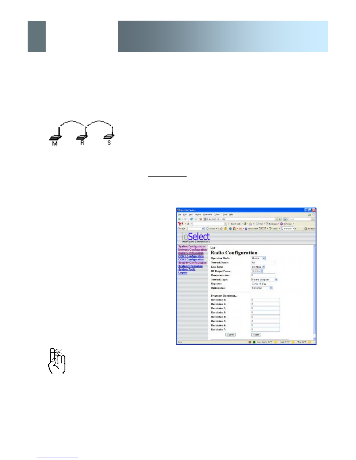
A 4-node network consisting of a Master, 1 Repeater, and 2 Remotes. 1 Remote is to communicate with the Master through a Repeater; the other is to communicate directly with the Master.
Refer to Section 6.1.4 for
important information
regarding the configuration of
a PMP Master’s
Retransmissions.
© ioSelect Inc. CONFIDENTIAL 28
Image 5C: PMP Example 5.2.1: Master
· There is no DESTINATION UNIT displayed as, in PMP,
the DESTINATION is preset to 65535: the BROADCAST address (‘multipoint’).
· RETRANSMISSIONS are set to 0. Refer to Section
6.1.4 for more information.
· There is a REPEATER in this example network, therefore the MASTER’s ‘Repeater’ configuration option is
set to Yes.
Page 29
ioSelect
5.0 Network Topologies
EtherWave - WMR
Example 5.2.1 (continued)
When bench testing PMP with
a REPEATER in the network,
configure the REMOTE to
synchronize to the
REPEATER via the
REMOTE’s ROAMING
ADDRESS field. If this is not
done, with the REMOTE in
close proximity to the
MASTER and its ROAMING
set as 1 (default), the
REMOTE will simply
synchronize with (and pass
data directly to) the MASTER,
bypassing the REPEATER
altogether.
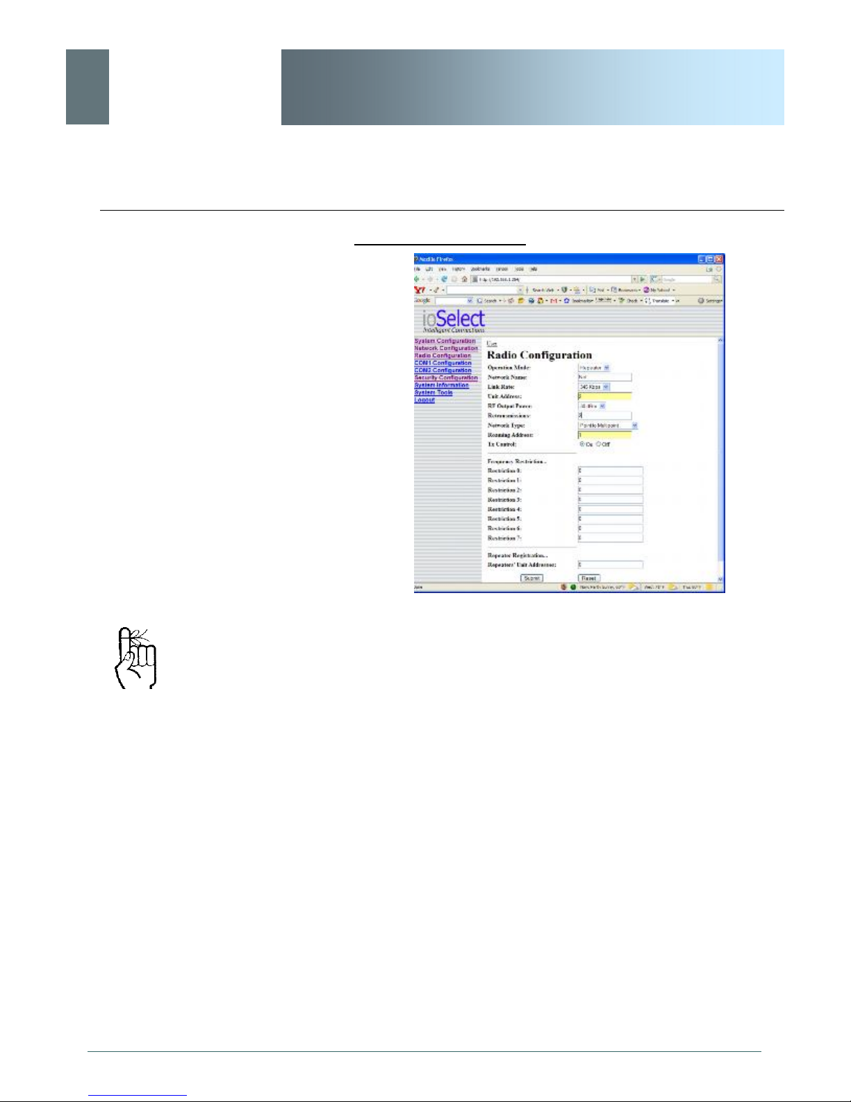
Image 5D: PMP Example 5.2.1: Repeater
· The ROAMING address for the REPEATER is set to 1:
the UNIT ADDRESS of the MASTER. This means that
this REPEATER will synchronize to, and communicate
directly with, the MASTER.
· There is no DESTINATION UNIT field for remote units
in a PMP network: the destination is predefined as
‘1’ (the MASTER ‘point’).
On the following page are the configurations for the REMOTES.
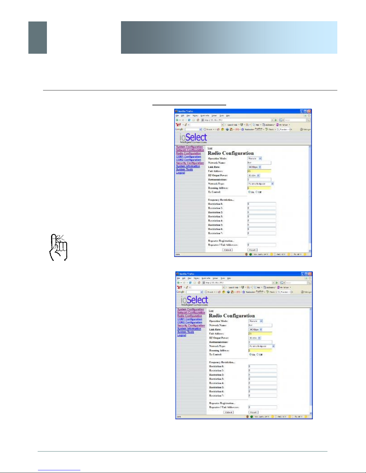
· Remote 20’s ROAMING ADDRESS is set to 2, the
UNIT ADDRESS of the REPEATER. This Remote will
synchronize to the Repeater and communicate via the
Repeater to the Master.
· Remote 30’s ROAMING ADDRESS is set to 1 (the
UNIT ADDRESS of the MASTER): it will synchronize
to, and communicate directly with, the MASTER.
© ioSelect Inc. CONFIDENTIAL 29
Page 30
ioSelect
5.0 Network Topologies
EtherWave - WMR
Example 5.2.1 (continued)
Each modem in any network
must have a unique Unit
Address.
Image 5E: PMP Example 5.2.1: Remote 20
Image 5F: PMP Example 5.2.1: Remote 30
© ioSelect Inc. CONFIDENTIAL 30
Page 31
ioSelect
5.0 Network Topologies
EtherWave - WMR
5.3 Peer-to-Peer (P2P)
P2P mode is used for communications between pairings of remote
modems,
e.g. Remote 20 can exchange data with (only) Remote 30,
Remote 21 can exchange data with (only) Remote 35, etc.
A P2P network requires a
Master modem.
The data being transmitted
from one Remote to another
in P2P mode is transferred
via the Master.
The Master will resend the data incoming to it from both Remotes to
both/all Remotes; one Remote’s data has a Destination Unit being
the other Remote and vice versa.
Example 5.3.1
A device located at a pump station must communicate bidirectionally with another device at a water tank. The MASTER
EtherWave-WMR must reside in an office at a separate location.
© ioSelect Inc. CONFIDENTIAL 31
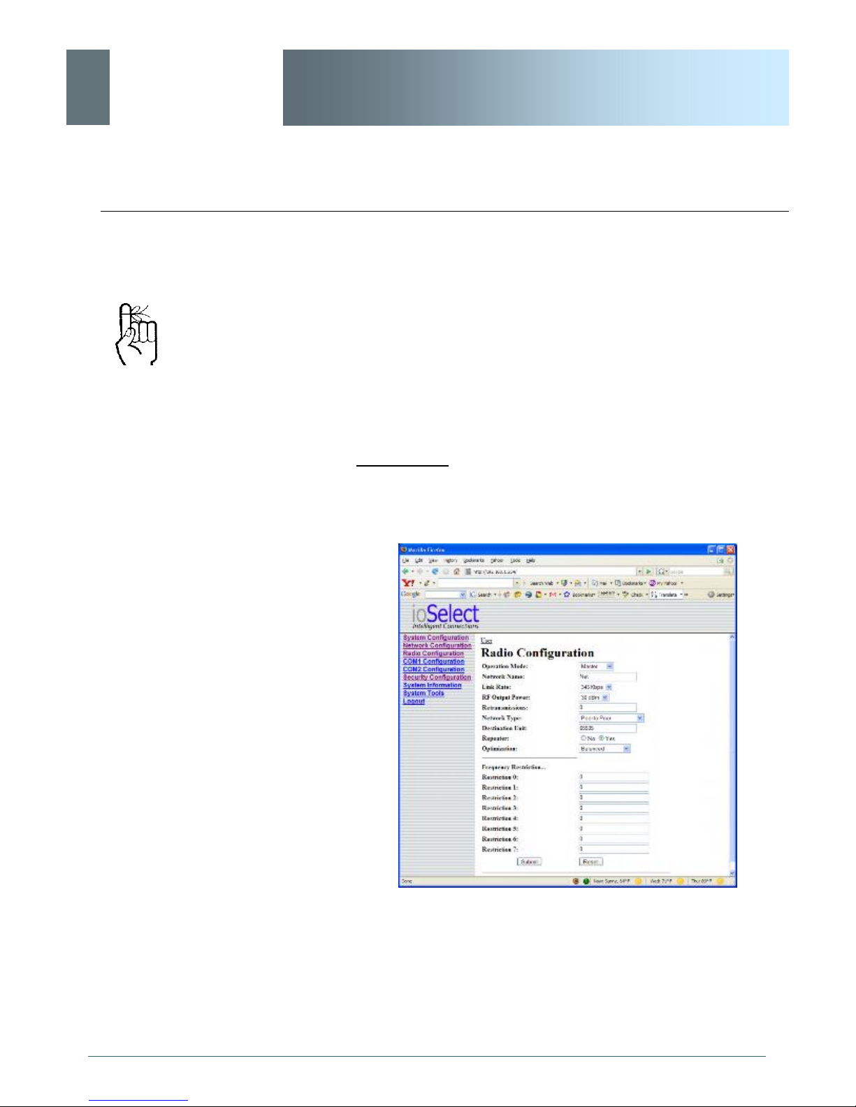
Image 5G: P2P Example 5.3.1: Master
All EtherWave-WMR within a particular network must be configured
to have the same Network Type.
continued...
Page 32
ioSelect
5.0 Network Topologies
EtherWave - WMR
Example 5.3.1 (continued)
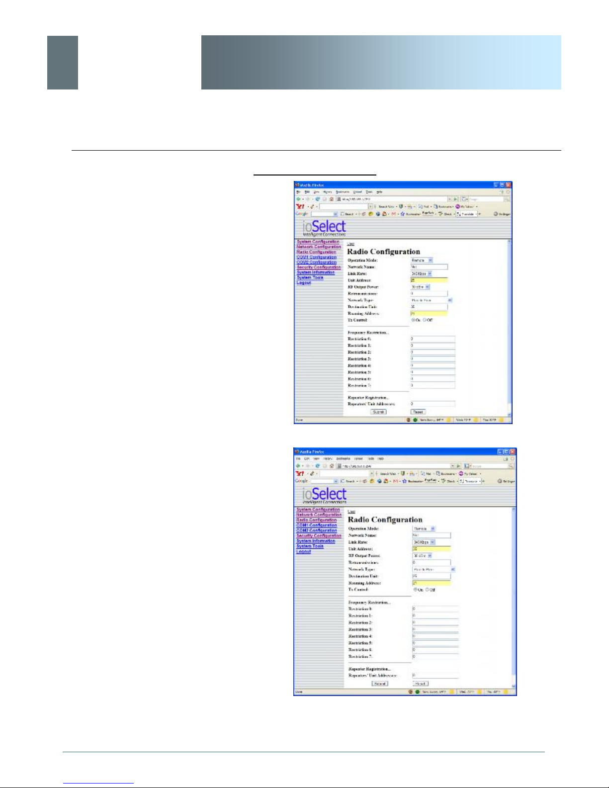
Image 5H: P2P Example 5.3.1: Remote 25
Image 5I: P2P Example 5.3.1: Remote 35
© ioSelect Inc. CONFIDENTIAL 32
Page 33
ioSelect
5.0 Network Topologies
EtherWave - WMR
5.4 Everyone-to-Everyone (E2E)
E2E mode is used for communications between all remote modems,
i.e. data from every modem is broadcast to every other
modem in the network.
An E2E network requires a
Master modem.
The data being transmitted
from remote units in an E2E
network travels to the Master
and is then re-broadcast to all
other remotes.
Considering the amount of data re-broadcasting (via the Master), it
is a very bandwidth-intensive network topology.
Example 5.4.1
1 Master and 3 remote units must all communicate with each other.
© ioSelect Inc. CONFIDENTIAL 33
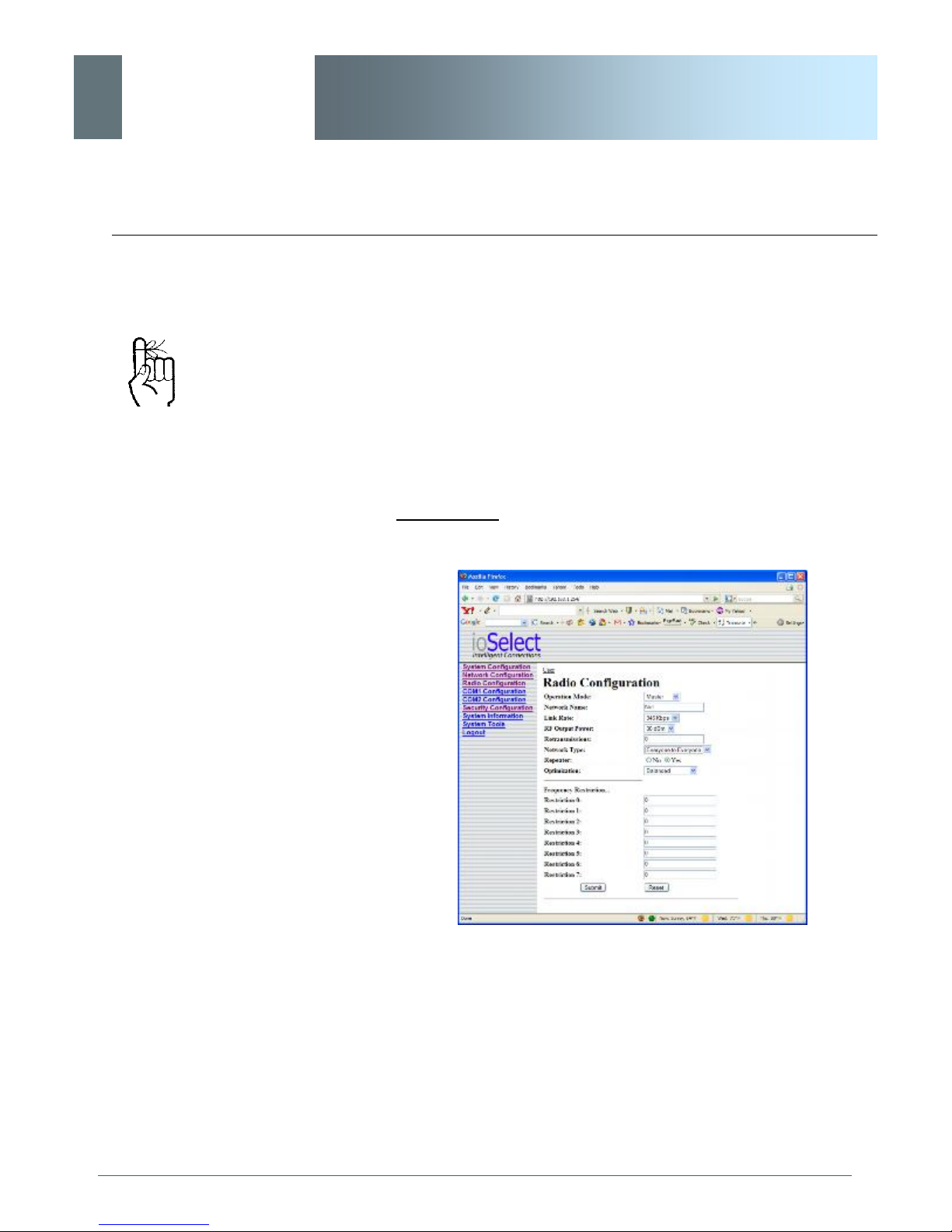
Image 5J: E2E Example 5.4.1: Master
· There is no DESTINATION UNIT configuration option
as the DESTINATION is predefined to be the broadcast
address (65535) when in E2E mode.
Page 34
ioSelect
5.0 Network Topologies
Each unit must have its
own unique Unit Address.
EtherWave - WMR
Example 5.4.1 (continued)
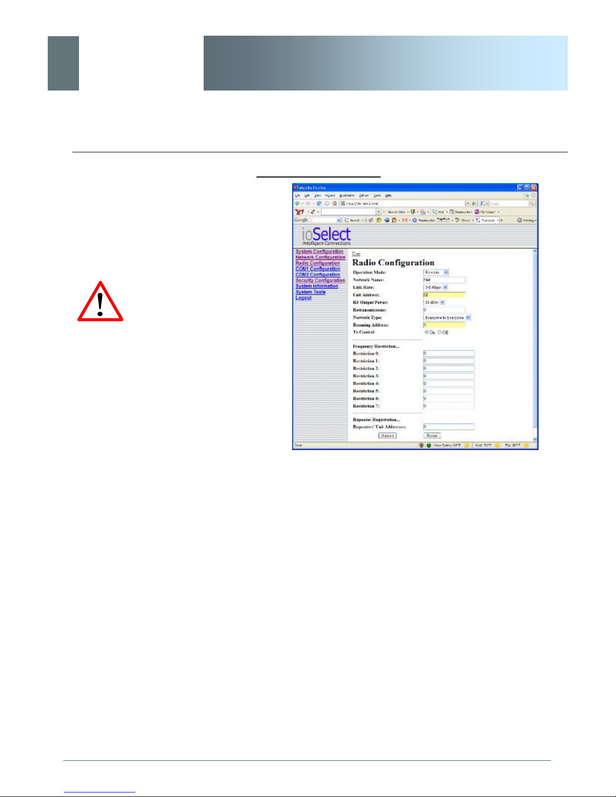
Image 5K: E2E Example 5.4.1: Remote
The Remotes will all be configured as per the above screen capture, with the exception of the UNIT ADDRESS. Each Remote (of
the 3 in this example) must have its own unique UNIT ADDRESS,
e.g. 50, 51, and 52.
© ioSelect Inc. CONFIDENTIAL 34
Page 35

ioSelect
6.0 Configuration
EtherWave - WMR
The following factors must be considered when preparing to configure the modems:
· the application
· network topology
· physical distribution of the network
· data interface requirements
Components involved in the configuration process of the EtherWaveWMR:
· interfacing with the modem, and
· selecting and inputting the desired operational parame-
ters
Interfacing to the EtherWave-WMR for the purpose of initially configuring it may be accomplished in one of two ways:
· front COM2 connector, IoSelect Inc. DE9-RJ45 Diagnostics Cable, and a PC running terminal communications
program (e.g. HyperTerminal), or
· rear ETHERNET (RJ45) port, ethernet crossover cable,
and PC running IoSelect Inc. DiscoverIP utility and Web
Browser application.
All configuration of the EtherWave-WMR is accomplished with a PC.
There are no DIP switches to set; switches which may subsequently
become inadvertently misadjusted or intermittent.
© ioSelect Inc. CONFIDENTIAL 35
Page 36

ioSelect
6.0 Configuration
The modem will arrive from
the factory with DHCP
enabled and a unique random
Class D IP address.
The DiscoverIP utility is
utilized to ’discover’ the IP
address of the EtherWaveWMR (not other devices on
network) so that you may
specifically address it (in Web
Browser URL line) for
configuration purposes.
EtherWave - WMR
6.1 Web User Interface
Initial configuration of an EtherWave-WMR using the Web User
(Browser) Interface (Web UI) method involves the following steps:
· connect EtherWave-WMR ETHERNET port to PC NIC card
using an ethernet crossover cable
· apply power to the EtherWave-WMR and wait approximately 1
minute for the system to load
· run IoSelect Inc. DiscoverIP Utility on the PC (see Appendix A
for complete details on this convenient utility)
· within the DiscoverIP Utility window, click on the desired unit’s
IP address (verify displayed MAC address with MAC address
printed on sticker on bottom of unit)
·
· logon window appears; log on
· configure EtherWave-WMR as desired.
In this section, all aspects of the Web Browser Interface, presented
menus, and available configuration options will be discussed.
© ioSelect Inc. CONFIDENTIAL 36
Page 37
ioSelect
6.0 Configuration
EtherWave - WMR
6.1.1 Logon Window
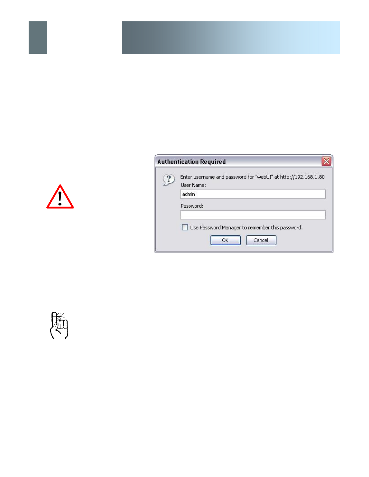
Upon successfully accessing the EtherWave-WMR using a Web
Browser, the Logon window will appear.
For security, do not allow the
web browser to remember the
User Name or Password.
It is advisable to change the
login Password (see Section
6.1.6.1). Do not FORGET the
new password as it cannot be
recovered.
Image 6A: Logon Window
The factory default User Name is: admin
The default password is: admin
Note that the password is case sensitive. It may be changed
(discussed further along in this section), but once changed, if
forgotten, may not be recovered.
© ioSelect Inc. CONFIDENTIAL 37
Page 38
ioSelect
6.0 Configuration
EtherWave - WMR
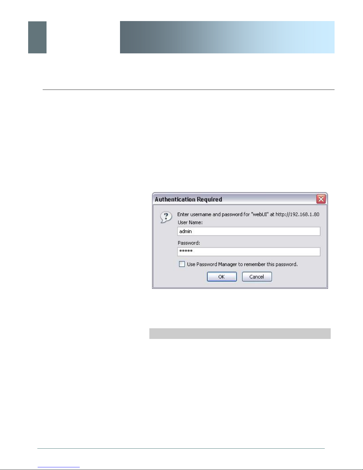
When entered, the password appears as ’dots’ as shown in the
image below. This display format prohibits others from viewing the
password.
The ‘Remember my password’ checkbox may be selected for
purposes of convenience, however it is recommended to ensure it
is deselected - particularly once the unit is deployed in the field for one primary reason: security.
© ioSelect Inc. CONFIDENTIAL 38
Image 6B: Logon Window With Password Input
Soft Buttons
· OK
Inputs the selected values into the EtherWave-WMR for
processing.
· Cancel
Page 39
ioSelect
6.0 Configuration
EtherWave - WMR
6.1.2 Welcome Window
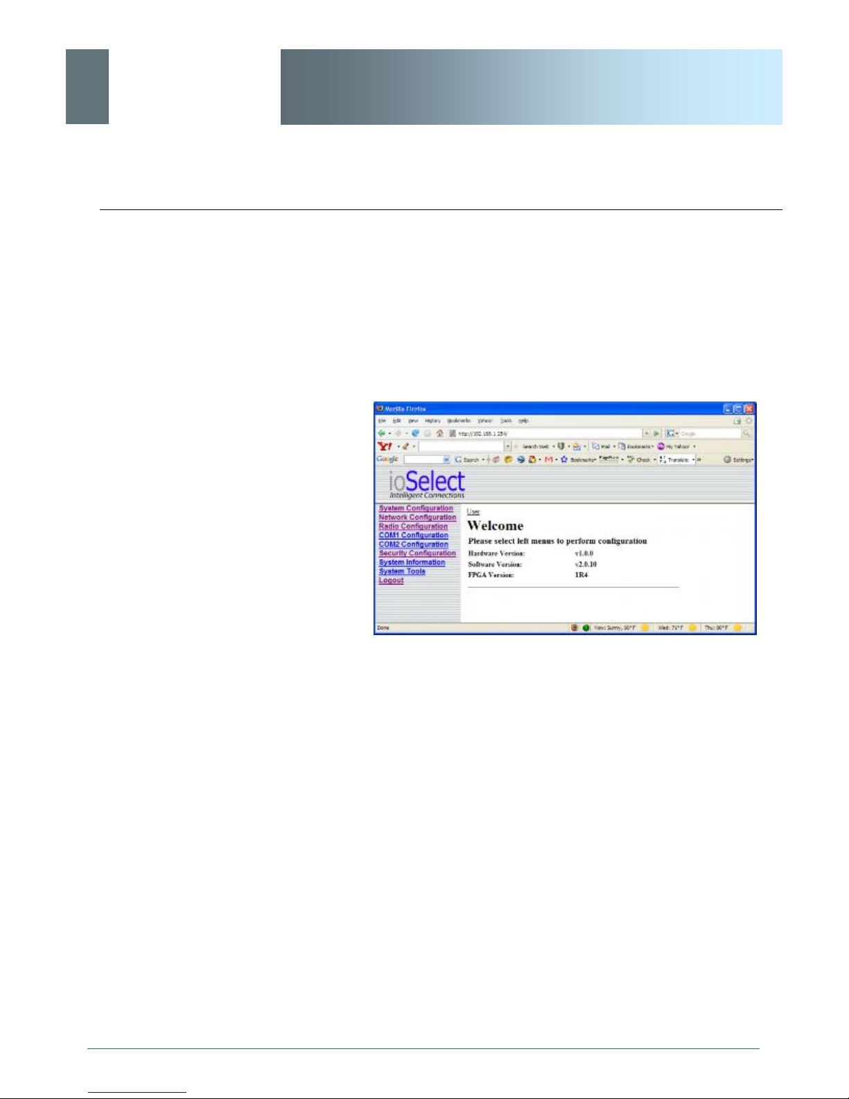
The Welcome window displays the specific EtherWave-WMR’ name
(entered as the Radio Description in the System Configuration
menu). This name quickly confirms the ’identity’ of the unit being
perused and appears in all menu windows.
© ioSelect Inc. CONFIDENTIAL 39
Image 6C: Welcome Window
Also displayed is various ‘version’ information:
· Hardware Version - applicable to the motherboard of
the EtherWave-WMR
· Software Version - this software resides on the
motherboard and is also referred to as the unit’s
’firmware’
· FPGA Version - Field Programmable Gate Array resides on the motherboard and relates to the interface
between the motherboard and radio module
Page 40
ioSelect
System Operation Mode
6.0 Configuration
EtherWave - WMR
6.1.3 System Configuration
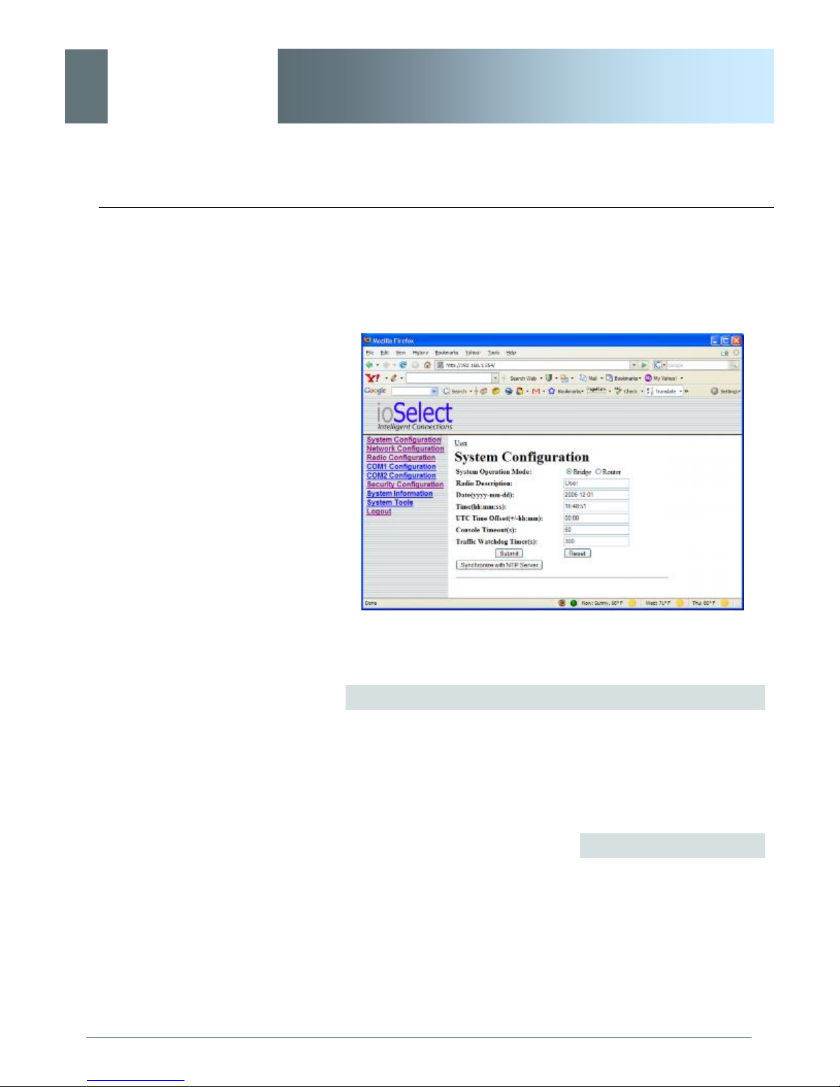
As per the previous section, the Radio Description is defined within
this menu, as are an assortment of other configuration options.
Image 6D: System Configuration Window
The radio button options presented here determine whether the
EtherWave-WMR unit will operate at a BRIDGE or a ROUTER.
Only a MASTER unit should ever be configured as a router.
Select the System Operation Mode ‘first’, i.e. prior to configuring
other options within the unit.
Values
Bridge
Bridge
Router
© ioSelect Inc. CONFIDENTIAL 40
Page 41

ioSelect
6.0 Configuration
The Radio Description must
not be confused with the
Network Name (Radio
Configuration menu). The
Network Name MUST be
exactly the same on each unit
within an EtherWave-WMR
EtherWave - WMR
Radio Description
The Radio Description is simply a convenient identifier for a specific
EtherWave-WMR, e.g. Pump Station 5, 123 Main Street, etc. This
feature is most welcome when accessing units from afar with large
networks: a convenient cross-reference for the unit’s IP address.
This ‘name’ appears in all menu windows. It has no bearing on the
unit’s operation.
Values
default is model-dependent
up to 30 characters
Date (yyyy-mm-dd)
The calendar date may be entered in this field. Note that the
entered value is lost should the EtherWave-WMR lose power for
some reason.
Values
2007-05-07 (varies)
valid date values, where
yyyy = 4-digit year
mm = 2-digit month
dd = 2-digit day
Time (hh:mm:ss)
The calendar date may be entered in this field. Note that the
entered value is lost should the EtherWave-WMR lose power for
some reason.
Values
11:27:28 (varies)
© ioSelect Inc. CONFIDENTIAL 41
valid time values, where
hh = 2-digit hours
mm = 2-digit minutes
ss = 2-digit seconds
Page 42

ioSelect
Soft Buttons
hh:mm)
6.0 Configuration
EtherWave - WMR
UTC Time Offset (+/-
Input the Universal Coordinated Time offset in this field, if so
desired. + indicates that local time is ahead of UTC time; - behind.
Values
00:00
valid time values, where
hh = 2-digit hours
mm = 2-digit minutes
Console Timeout (s)
This value determines when the console connection (made via
COM2) will timeout after becoming inactive.
Values
seconds
60
0-65535
· Synchronize with NTP Server
Useable to have related parameters on this page updated
with current time values when valid NTP Server information
has been configured and the service is enabled within the
modem (see Section 6.1.3.2 for additional information).
· Submit
Write parameter values into EtherWave-WMR memory.
© ioSelect Inc. CONFIDENTIAL 42
· Reset
Restore ‘currently’ modified parameter values to those
which were previously written into EtherWave-WMR
Page 43
ioSelect
6.0 Configuration
EtherWave - WMR
6.1.4 Network Configuration
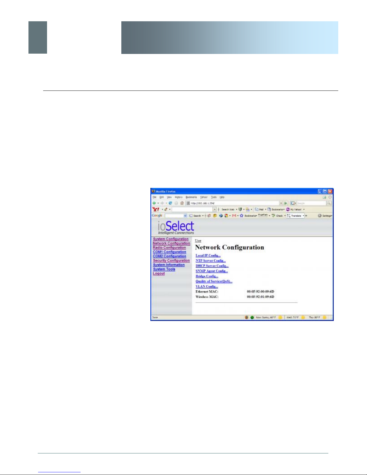
The Network Configuration menu consists of a number of
submenus, all of which provide various options pertaining to
configuring the units to be part of an IP network. These settings do
not effect the ‘radio’ communications network aspect of the system,
however, be mindful of the Network Type (Radio Configuration
menu) as that dictates the possibilities for the flow of network data.
For a basic implementation, only the Local IP Configuration
(submenu) options need to be defined.
© ioSelect Inc. CONFIDENTIAL 43
Image 6E: Network Configuration, Top Level Menu
The Ethernet MAC address (as displayed above) is that of the
ETHERNET interface located at the rear of the EtherWave-WMR.
The Wireless MAC address is for internal purposes.
Page 44
ioSelect
IP Address Mode
6.0 Configuration
DHCP: Dynamic Host
Configuration Protocol may
be used by networked
devices (Clients) to obtain
unique network addresses
from a DHCP server.
EtherWave - WMR
6.1.4.1 Local IP Configuration
6.1.4.1.1 Bridge
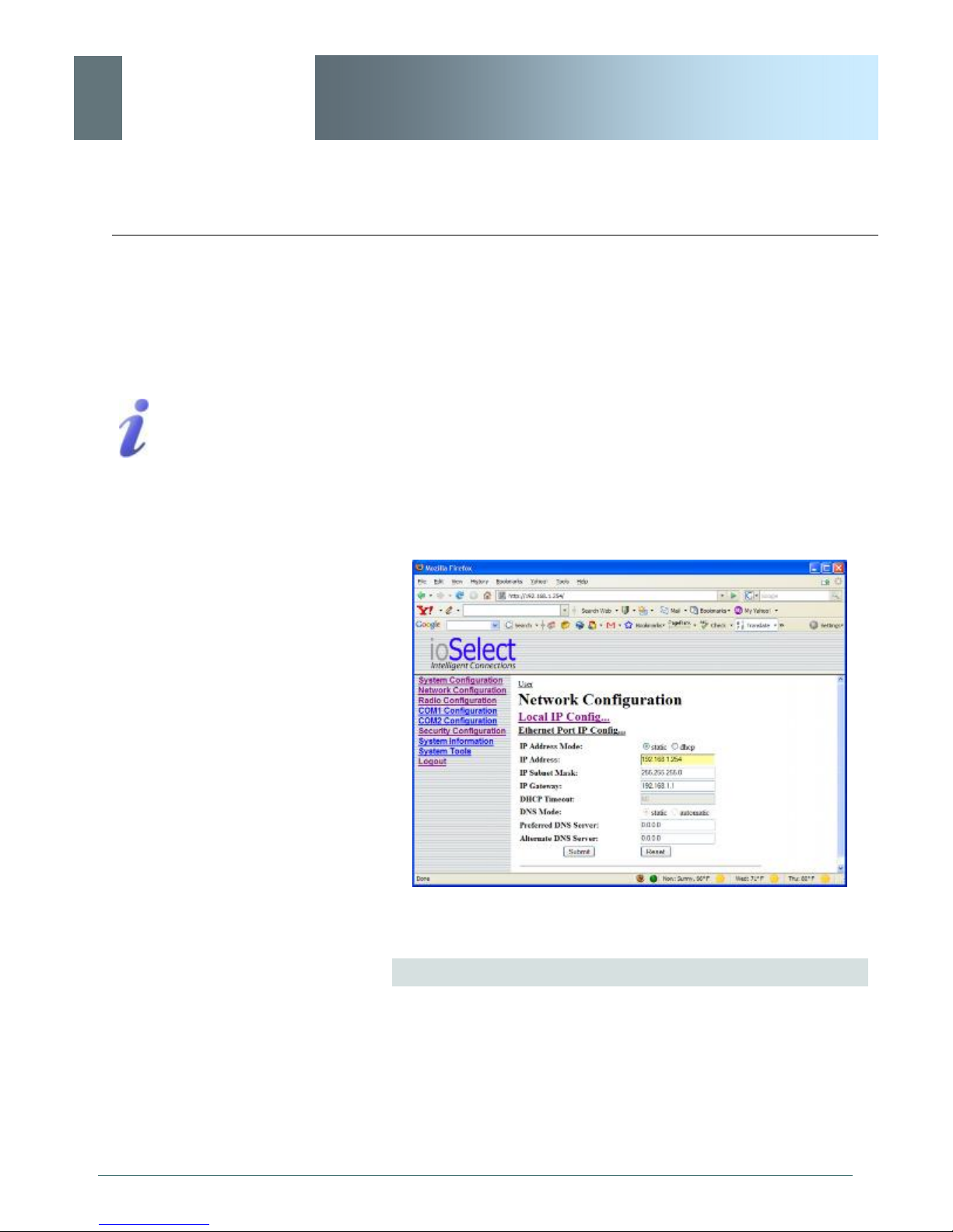
This submenu, along with Radio Configuration settings, are the
minimum which must be considered when implementing any
EtherWave-WMR network.
It must be determined if the unit is to be either:
· assigned an IP address (by a DHCP server), or
· given a static (unchanging) IP address.
Once the above is ascertained, the items within this submenu may
be configured.
Advantage:
Ensures unique IP addresses
are assigned, from a central
point (DHCP server) within a
network.
Disadvantage:
The address of a particular
device is not ‘known’ and is
also subject to change.
STATIC addresses must be
tracked (to avoid duplicate
use), yet they may be
permanently assigned to a
device.
Image 6F: Network Configuration (Bridge), Local IP Configuration
Submenu
If ‘static’ is selected, the three following fields (see Image 6F) are to
be manually populated with values which will suit the network/
devices to which the EtherWave-WMR is connected.
© ioSelect Inc. CONFIDENTIAL 44
continued...
Page 45

ioSelect
IP Address Mode (continued)
6.0 Configuration
If DHCP mode is selected,
but there is no DHCP server
available, after the DHCP
timeout period the units will
default to function simply as a
’wireless bridge’.
EtherWave - WMR
If ‘DHCP’ is selected, the three following fields (see Image 6F) will
be automatically populated by the DHCP server. The DHCP
Timeout value may be manually modified from the factory default
value.
Note that the factory default setting is DHCP.
Values
dhcp
static
dhcp
Within any IP network, each
device must have its own
unique IP address.
A SUBNET MASK is a bit
mask that separates the
network and host (device)
portions of an IP address.
The ‘unmasked’ portion
leaves available the
information required to
identify the various devices
on the subnet.
IP Address
If DHCP is selected (see above), a unique IP address will be
assigned to the EtherWave-WMR; if STATIC IP address mode has
been selected, enter a suitable value for the specific network.
Values
192.168.1.254
valid value is specific to the
network
Subnet Mask
For a small private network with IP addresses appearing similar to
192.168.1.xx (Class C address), the standard 255.255.255.0
subnet mask may be applicable.
If DHCP mode is selected (see above/top), the DHCP server will
populate this field.
Values
255.255.255.0
valid value is specific to the
network
© ioSelect Inc. CONFIDENTIAL 45
Page 46

ioSelect
6.0 Configuration
EtherWave - WMR
IP Gateway
If the EtherWave-WMR devices are integrated into a network which
has a defined gateway, then, as with other hosts on the network,
this gateway’s IP address will be entered into this field. If there is a
DHCP server on the network, and the IP Address Mode (see
previous page) is selected to be DHCP, the DHCP server will
populate this field with the appropriate gateway address.
A GATEWAY is a point within
a network that acts as an
entrance to another network.
In typical networks, a router
acts as a gateway.
In a very small network (e.g. point-to-point, and STATIC IP Address
Mode), the gateway value is not critical. The IP address of the
most significant device on the overall network may be entered, or, if
only two EtherWave-WMR’s are being used, make the gateway of
EtherWave-WMR No. 1 = IP address of EtherWave-WMR No. 2;
gateway of EtherWave-WMR No. 2 = IP address of EtherWaveWMR No. 1. The idea behind this approach is: If an EtherWaveWMR at ‘one end’ of a wireless link receives a packet it is unsure
where to send, send it to the other end of the wireless link (i.e. the
other EtherWave-WMR) where it was quite likely destined.
A simple way of looking at what the gateway value should be is: If
a device has a packet of data is does not know where to send, send
it to the gateway. If necessary - and applicable - the gateway can
forward the packet onwards to another network.
Values
192.168.1.1
valid value is specific to the
network
DHCP Timeout
© ioSelect Inc. CONFIDENTIAL 46
This value determines for how long the EtherWave-WMR will await
to receive information from a DHCP server. If this timeout expires,
the unit will assign itself a random Class D IP address (and subnet
mask) and function simply as a wireless bridge.
Values
seconds
60
1-65535
Page 47

ioSelect
6.0 Configuration
EtherWave - WMR
DNS Mode
The setting determines whether the EtherWave-WMR unit will have
its DNS Server information entered manually (static) or if it will
obtain the information (provided it is available) via the connected
network.
Values
static
automatic
Preferred DNS Server
If DNS Mode is static, enter valid IP Address of accessible
Preferred DNS Server in this field.
Values
0.0.0.0
valid DNS Server IP address
Alternate DNS Server
If DNS Mode is static, enter valid IP Address of accessible Alternate
DNS Server in this field.
Values
0.0.0.0
valid DNS Server IP address
Soft Buttons
· Submit
Write parameter values into EtherWave-WMR memory.
· Reset
Restore ‘currently’ modified parameter values to those
which were previously written into EtherWave-WMR
memory.
© ioSelect Inc. CONFIDENTIAL 47
Page 48
ioSelect
6.0 Configuration
Only the MASTER
EtherWave-WMR unit may be
configured as a Router.
EtherWave - WMR
6.1.4.1 Local IP Configuration
6.1.4.1.2 Router
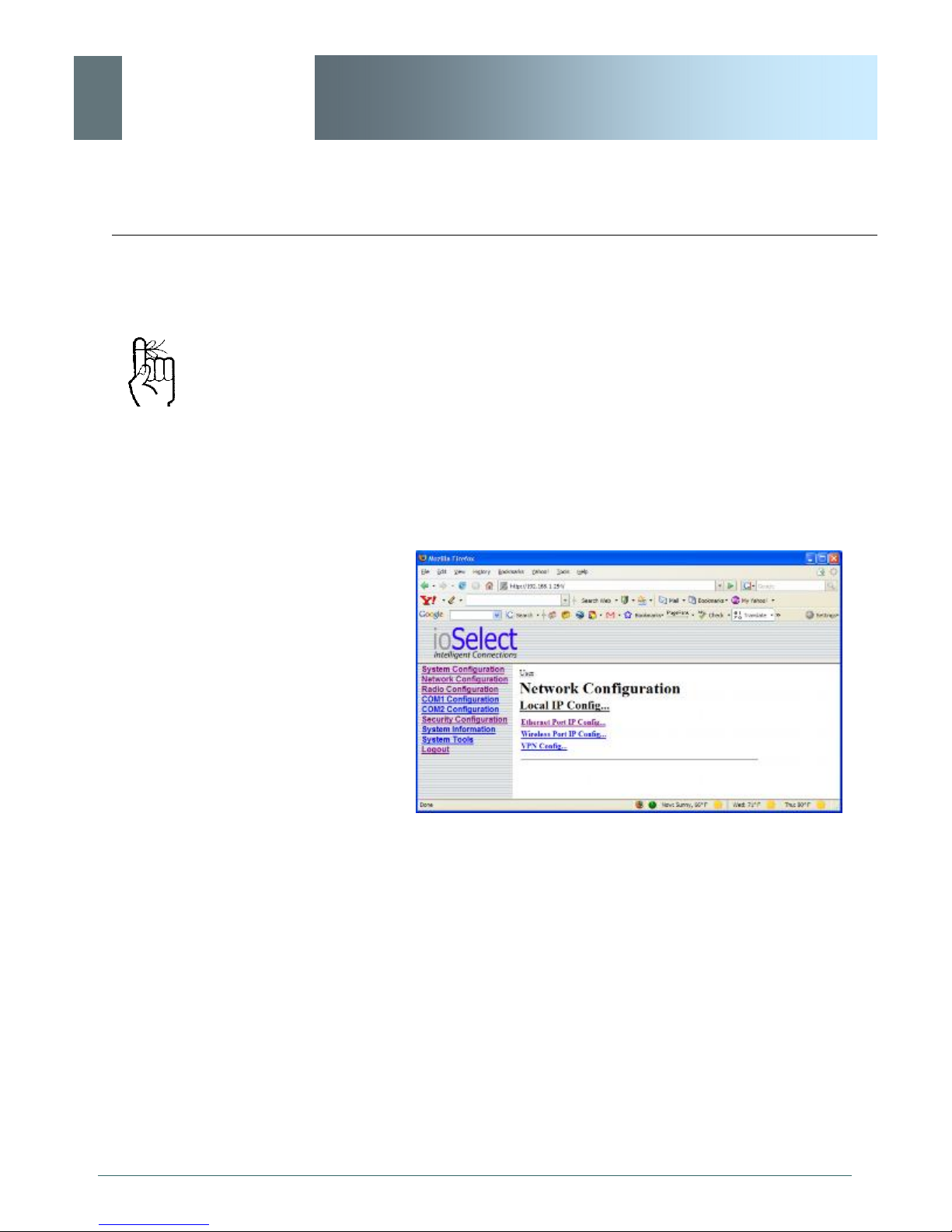
If the EtherWave-WMR unit has been configured as a Router
(under the System Configuration menu), the Network Configuration
will present some additional options to those presented if the unit
was configured as a Bridge.
The Ethernet Port IP Configuration applies to the ‘wired’ port (at
rear of EtherWave-WMR unit), which may also be considered as
the WAN (Wide Area Network) port.
The Wireless Port IP Configuration applies to the LAN (Local Area
Network): the LAN consists of the devices, and EtherWave-WMR
units, connected to each other via the wireless (radio) network.
© ioSelect Inc. CONFIDENTIAL 48
Image 6G: Network Configuration (Router), Local IP Configuration
Submenu
Refer to the preceding section for configuring the Ethernet Port,
keeping in mind that the settings apply only to the ‘wired’
connection of the MASTER unit.
There are two other options to be discussed further on the following
pages:
· Wireless Port IP Configuration
· VPN Configuration
Page 49
ioSelect
6.0 Configuration
EtherWave - WMR
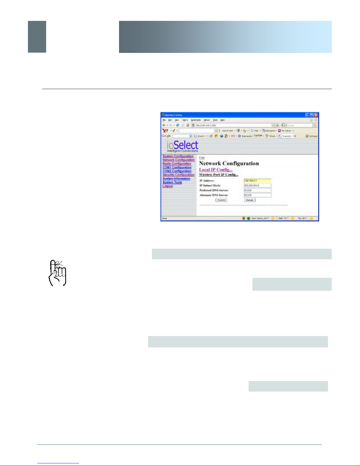
6.1.4.1.2.1 Wireless Port IP Configuration
Within any IP network, each
device must have its own
unique IP address.
Image 6H: Network Configuration (Router), Wireless Port IP
Configuration Submenu
IP Address
This address MUST be STATIC (i.e. DHCP is not applicable).
Values
192.168.2.1
valid value is specific to the
network, typically a Class C
private IP
Subnet Mask
For a small private network with IP addresses appearing similar to
192.168.1.xx (Class C address), the standard 255.255.255.0
subnet mask may be applicable.
Values
255.255.255.0
© ioSelect Inc. CONFIDENTIAL 49
valid value is specific to the
network
Page 50

ioSelect
6.0 Configuration
EtherWave - WMR
Preferred DNS Server
If applicable, enter valid IP address of Preferred DNS Server which
exists within the LAN (the wireless subnet) in this field.
Values
0.0.0.0
valid DNS Server IP address
Alternate DNS Server
If applicable, enter valid IP address of Alternate DNS Server which
exists within the LAN (the wireless subnet) in this field.
· Submit
Write parameter values into EtherWave-WMR memory.
· Reset
Restore ‘currently’ modified parameter values to those
which were previously written into EtherWave-WMR
memory.
Values
0.0.0.0
valid DNS Server IP address
Soft Buttons
© ioSelect Inc. CONFIDENTIAL 50
Page 51
ioSelect
6.0 Configuration
VPN: Virtual Private Network.
A communications path
connecting a device on a
WAN with a device on a LAN.
EtherWave - WMR
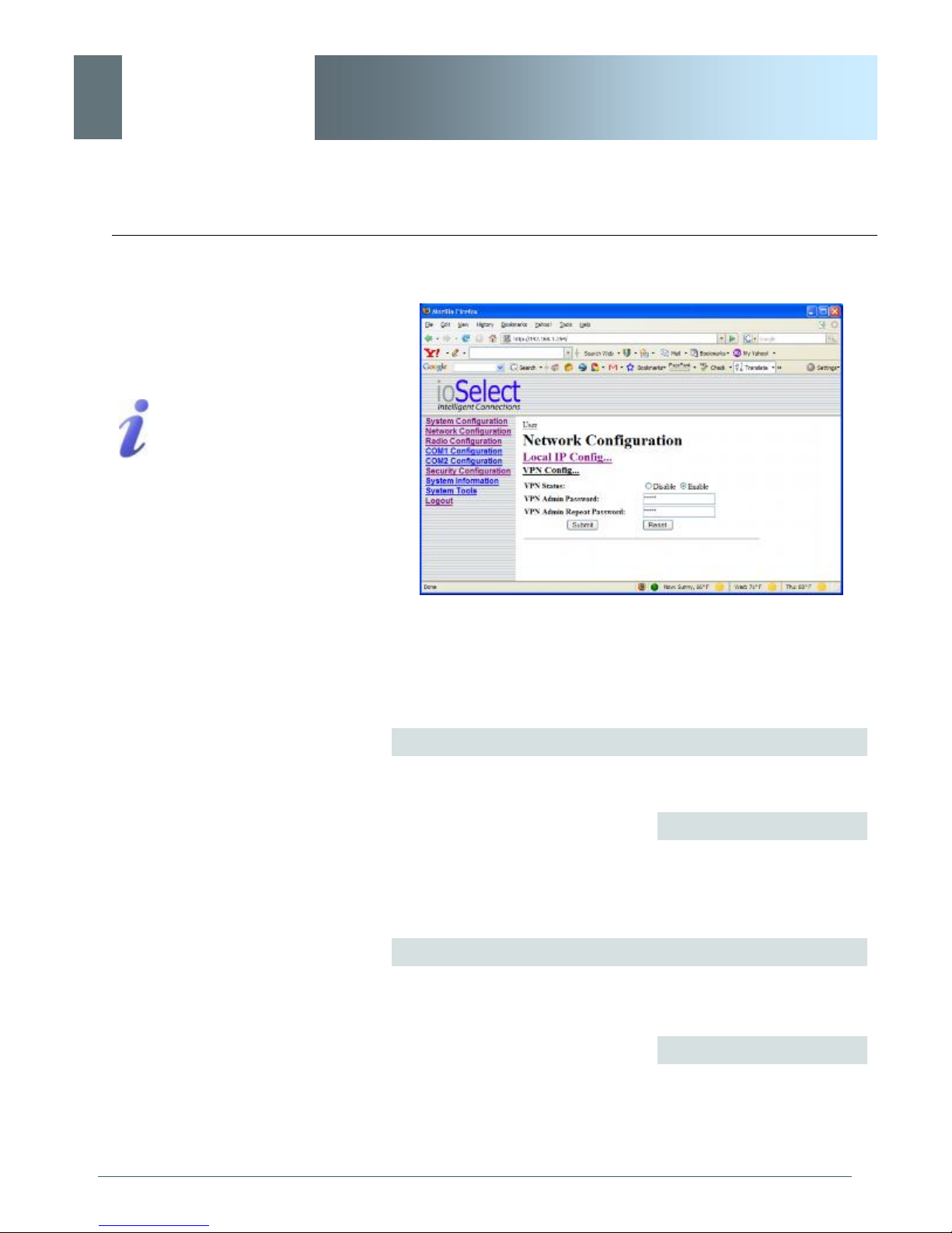
6.1.4.1.2.2 VPN Configuration
Image 6I: Network Configuration (Router), VPN Configuration
Submenu
A Virtual Private Network (VPN) may be configured to enable a direct
communications link between one device on the WAN and another
on the LAN.
VPN Status
Enable (default) enables the service; Disable disables it.
Values
Enable
Enable
Disable
VPN Admin Password
Select a unique password of 32 characters maximum, casesensitive.
Values
© ioSelect Inc. CONFIDENTIAL 51
admin
32 characters maximum
Page 52

ioSelect
6.0 Configuration
EtherWave - WMR
VPN Admin Repeat Password
Enter the same unique password of 32 characters maximum, casesensitive, which was entered in the preceding/above field.
Values
admin
32 characters maximum
Soft Buttons
· Submit
Write parameter values into EtherWave-WMR memory.
· Reset
Restore ‘currently’ modified parameter values to those
which were previously written into EtherWave-WMR
memory.
© ioSelect Inc. CONFIDENTIAL 52
Page 53
ioSelect
6.0 Configuration
NTP may be used to
synchronize the time in the
EtherWave-WMR within a
network to a reference time
EtherWave - WMR
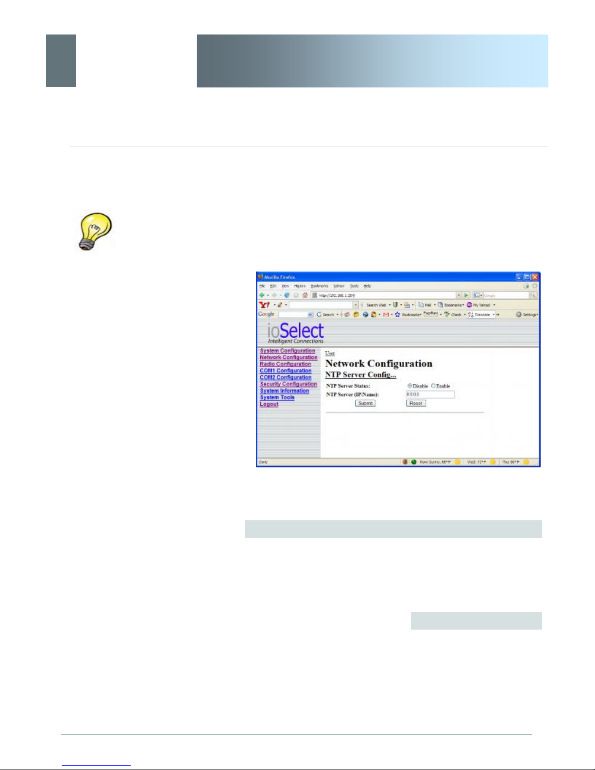
6.1.4.2 NTP Server Configuration
The Network Time Protocol (NTP) feature may be ENABLED,
provided there is an NTP server available and its IP address or
’name’ is entered in the appropriate field.
© ioSelect Inc. CONFIDENTIAL 53
Image 6G: Network Configuration, NTP Server Config. Submenu
NTP Server Status
Note that if NTP Server Status is ENABLED, the ‘Synchronize with
NTP Server’ soft button on the System Configuration menu will be
available for use.
Leave as DISABLED (default) if a server is not available.
Values
Disable
Disable
Enable
Page 54

ioSelect
6.0 Configuration
EtherWave - WMR
NTP Server (IP/Name)
IP address or domain name for NTP server (on local LAN or
website (provided that Internet access is available)) is to be entered
in this field if the NTP Server Status is configured as ENABLED.
Values
0.0.0.0
valid NTP server IP address
or ‘name’
· Submit
Write parameter values into EtherWave-WMR memory.
· Reset
Restore ‘currently’ modified parameter values to those
which were previously written into EtherWave-WMR
memory.
Soft Buttons
© ioSelect Inc. CONFIDENTIAL 54
Page 55

ioSelect
6.0 Configuration
EtherWave - WMR
6.1.4.3 DHCP Server Configuration
There is a difference in how the DHCP Server operates based on
whether the EtherWave-WMR unit (Master) is configured to function
as a bridge or a router.
6.1.4.3.1 Bridge
The EtherWave-WMR Master may be configured to provide dynamic
host control protocol (DHCP) service to all attached (either wired or
wireless-connected) devices.
Configuration field descriptions are discussed in the following section.
6.1.4.3.2 Router
An EtherWave-WMR Master may be configured to provide dynamic
host control protocol (DHCP) service for an entire LAN (or section
thereof). Recall that the LAN consists of wirelessly connected EtherWave-WMR units and those IP addressable devices which are connected to them. If this feature is to be utilized, it would be enabled
on the Master EtherWave-WMR unit, noting that such a DHCP
Server service must not be enabled on any other EtherWave-WMR
units or devices which reside on the same network segment.
With this service enabled on the Master, it can assign IP addresses
(as well as subnet mask and gateway) to the LAN radios and IP devices attached to them provided they are set for DHCP as opposed
to static.
The DHCP Server may also be used to manage up to five MAC address bindings. MAC address binding is employed when certain devices are to be assigned specific IP addresses (effectively issuing
them a ‘static’ IP address). Such devices are identified by their
unique MAC address: the DHCP Server ensures that a specified IP
address is assigned to a specific MAC address (hence, device - either an EtherWave-WMR or other IP-based device attached to the
LAN).
© ioSelect Inc. CONFIDENTIAL 55
Page 56
ioSelect
6.0 Configuration
EtherWave - WMR
Prior to enabling this service,
verify that there are no other
devices - either wired (e.g.
LAN) or wireless (e.g. another
EtherWave-WMR) with an
active DHCP SERVER
service.
(The Server issues IP
address information at the
request of a DHCP Client,
which receives the
information.)
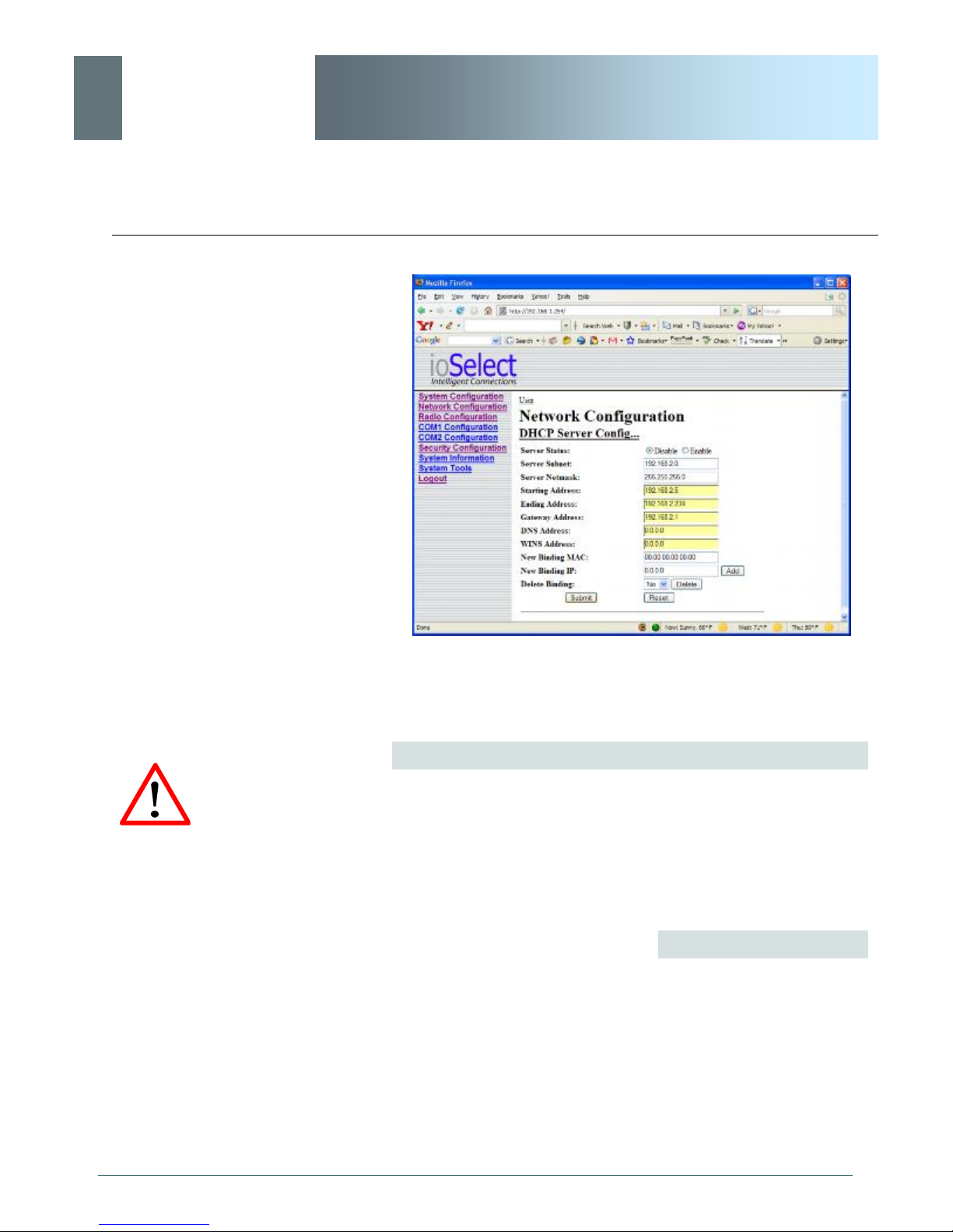
Image 6J: Network Configuration, DHCP Server Config. Submenu
Server Status
Choose to enable or disabled the DHCP Server service. Note that
there can only be one such service residing on a network segment otherwise, duplicate IP addresses could be assigned and exist on a
network, which would result in problems. Devices on the network,
which are intended to receive IP address information from this
DHCP Server, must have their local IP settings set for ‘DHCP’ (as
opposed to ‘static’)
Values
Disable
Disable
Enable
© ioSelect Inc. CONFIDENTIAL 56
Page 57

ioSelect
6.0 Configuration
EtherWave - WMR
Server Subnet
Not to be confused with the Server Netmask (see below). Enter the
network’s ‘root’ address, e.g. if devices are to be assigned
addresses such as 192.168.1.5 and 192.168.1.6, enter 192.168.1.0
in this field.
Values
192.168.2.0
valid server subnet value for
specific network
Server Netmask
In this field, input the subnet mask which is to be applied to the
network. For basic, small, private networks, a Class C subnet mask
such as 255.255.255.0 could be used.
Values
255.255.255.0
valid subnet mask value for
specific network
Starting Address
This is the starting (‘lower boundary’) IP address of the range of IP
addresses (also known as ’IP address pool’) to be issued by the
DHCP Server to the applicable devices on the network.
Values
192.168.2.5
IP address as per above
© ioSelect Inc. CONFIDENTIAL 57
Page 58

ioSelect
6.0 Configuration
EtherWave - WMR
Ending Address
This is the ending (‘upper boundary’) IP address of the range of IP
addresses to be issued by the DHCP Server to the applicable
devices on the network.
Values
192.168.2.239
IP address as per above
Gateway Address
Input the address of the desired gateway.
DNS: Domain Name Service
is an Internet service that
translates easilyremembered domain names
into their not-so-easilyremembered IP addresses.
Being that the Internet is
based on IP addresses,
without DNS, if one entered
the domain name
www.microhardcorp.com (for
example) into the URL line of
a web browser, the website
‘could not be found’).
WINS: Windows Internet
Naming Service keeps track
of which IP address is
assigned to which computer
on a Windows network: a
process known as name
resolution. It automatically
updates, which is particularly
important on a network where
DHCP is in use.
Values
192.168.2.1
IP address as per above
DNS Address
Input the IP address of the Domain Name Service (DNS) to be
provided by this DHCP Server.
Values
0.0.0.0
Valid DNS IP address
WINS Address
Windows Internet Naming Service (WINS) address to be provided
by this serv er.
Values
0.0.0.0
Valid WINS IP address
© ioSelect Inc. CONFIDENTIAL 58
Page 59

ioSelect
6.0 Configuration
EtherWave - WMR
New Binding MAC
In this field, input the MAC address (in specified format) of the
device to which a specific IP address is to be bound.
For the EtherWave-WMR, the MAC address of the unit may be
found on the label on the bottom of the unit, or it may be viewed on
the Network Configuration menu of that unit.
An address binding is a
mapping between a specific
IP address and the MAC
address of a specific client.
Values
00:00:00:00:00:00
MAC address of target
device
New Binding IP
Enter the IP address - from within the range identified with the
Starting Address and Ending Address parameters input previously which is to be ‘bound’ to the MAC address identified in the New
Binding MAC field (described above).
Values
0.0.0.0
IP address from within range
identified in Starting Address
and Ending Address fields
© ioSelect Inc. CONFIDENTIAL 59
Page 60

ioSelect
6.0 Configuration
EtherWave - WMR
Soft Buttons
· Add
After entering a New Binding MAC address and a New
Binding IP address, click this soft button to ADD this new
binding relationship.
Once ‘added’, the new relationship will be given a number
(e.g. Bound 1) and appear at the lower portion of the DHCP
Server Config. menu display, showing both the MAC and
corresponding IP address.
Note that the ADD action must be followed by SUBMIT for
the changes to be written to the EtherWave-WMR’s
memory.
· Delete
If binding relationships are present, the drop down box (to
left of Delete soft button) may be used to select a particular
binding, and the DELETE soft button used to delete it.
· Submit
Write parameter values into EtherWave-WMR memory.
· Reset
Restore ‘currently’ modified parameter values to those
which were previously written into EtherWave-WMR
© ioSelect Inc. CONFIDENTIAL 60
Page 61

ioSelect
6.0 Configuration
EtherWave - WMR
6.1.4.4 SNMP Agent Configuration
The EtherWave-WMR may be configured to operate as a Simple
Network Management Protocol (SNMP) agent.
Network management is most important in larger networks, so as to
be able to manage resources and measure performance.
SNMP: Simple Network
Management Protocol
provides a method of
managing network devices
from a single PC running
network management
software.
Managed networked devices
are referred to as SNMP
agents.
SNMP may be used in several ways:
· configure remote devices
· monitor network performance
· detect faults
· audit network usage
· detect authentication failures
A SNMP management system (a PC running SNMP management
software) is required for this service to operate. This system must
have full access to the EtherWave-WMR network. Communications
is in the form of queries (information requested by the management
system) or traps (information initiated at, and provided by, the SNMP
agent in response to predefined events).
Objects specific to the EtherWave-WMR are hosted under private
enterprise number 21703.
An object is a variable in the device and is defined by a Management
Information Database (MIB). Both the management system and the
device have a copy of the MIB. The MIB in the management system
provides for identification and processing of the information sent by a
device (either responses to queries or device-sourced traps). The
MIB in the device relates subroutine addresses to objects in order to
read data from, or write data to, variables in the device.
© ioSelect Inc. CONFIDENTIAL 61
An SNMPv1 agent accepts commands to retrieve an object, retrieve
the next object, set and object to a specified value, send a value in
response to a received command, and send a value in response to
an event (trap).
SNMPv2c adds to the above the ability to retrieve a large number of
objects in response to a single request.
SNMPv3 adds strong security features including encryption; a shared
password key is utilized. Secure device monitoring over the Internet
is possible. In addition to the commands noted as supported above,
there is a command to synchronize with a remote management station.
Page 62
ioSelect
6.0 Configuration
EtherWave - WMR
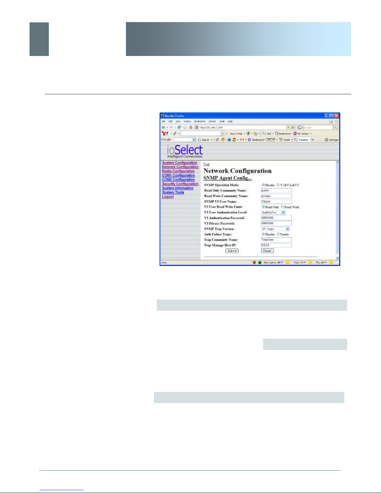
Image 6K: Network Configuration, SNMP Agent Config. Submenu
SNMP Operation Mode
If disabled, no SNMP service is provided from the device. Enabled,
the device - now an SNMP agent - can support SNMPv1, v2, & v3.
Values
Disable
Disable
V1&V2&V3
Read Only Community Name
Effectively a plain-text password mechanism used to weakly
authenticate SNMP queries. Being part of the community allows
the SNMP agent to process SNMPv1 and SNMPv2c requests. This
community name has only READ priority.
continued...
© ioSelect Inc. CONFIDENTIAL 62
Page 63

ioSelect
6.0 Configuration
EtherWave - WMR
Read Only Community Name (continued)
Values
public
character string
Read Write Community Name
Effectively a plain-text password mechanism used to weakly
authenticate SNMP queries. Being part of the community allows
the SNMP agent to process SNMPv1 and SNMPv2c requests. This
community name has only READ/WRITE priority.
Values
private
character string
SNMP V3 User Name
Defines the user name for SNMPv3.
Values
V3user
character string
V3 User Read Write Limit
Defines accessibility of SNMPv3; select either Read Only or Read/
Write priority. If Read Only is selected, the SNMPv3 user may only
read information; if Read Write is selected, the SNMPv3 user may
read and write (set) variables.
© ioSelect Inc. CONFIDENTIAL 63
Values
Read Only
Read Only
Read Write
Page 64

ioSelect
6.0 Configuration
EtherWave - WMR
V3 User Authentication Level
Defines SNMPv3 user’s authentication level.
NoAuthNoPriv: No authentication, no encryption.
AuthNoPriv: Authentication, no encryption.
AuthPriv: Authentication, encrpytion.
Values
NoAuthNoPriv
NoAuthNoPriv
AuthNoPriv
AuthPriv
V3 Authentication Password
SNMPv3 user’s authentication password. Only valid when V3 User
Authentication Level set to AuthNoPriv or AuthPriv (see above).
Values
00000000
character string
V3 Authentication Password
SNMPv3 user’s encryption password. Only valid when V3 User
Authentication Level set to AuthPriv (see above).
Values
00000000
character string
© ioSelect Inc. CONFIDENTIAL 64
Page 65

ioSelect
6.0 Configuration
EtherWave - WMR
SNMP Trap Version
Select which version of trap will be sent should a failure or alarm
condition occur.
Values
V1 Traps
V1 Traps
V2 Traps
V3 Traps
V1&V2 Traps
V1&V2&V3 Traps
Auth Failure Traps
If enabled, an authentication failure trap will be generated upon
authentication failure.
Values
Disable
Disable
Enable
Trap Community Name
The community name which may receive traps.
Values
TrapUser
character string
© ioSelect Inc. CONFIDENTIAL 65
Page 66

ioSelect
Soft Buttons
6.0 Configuration
EtherWave - WMR
Trap Manage Host IP
Defines a host IP address where traps will be sent to (e.g. SNMP
management system PC IP address).
Values
0.0.0.0
applicable host’s IP address
· Submit
Write parameter values into EtherWave-WMR memory.
· Reset
Restore ‘currently’ modified parameter values to those
which were previously written into EtherWave-WMR
memory.
© ioSelect Inc. CONFIDENTIAL 66
Page 67
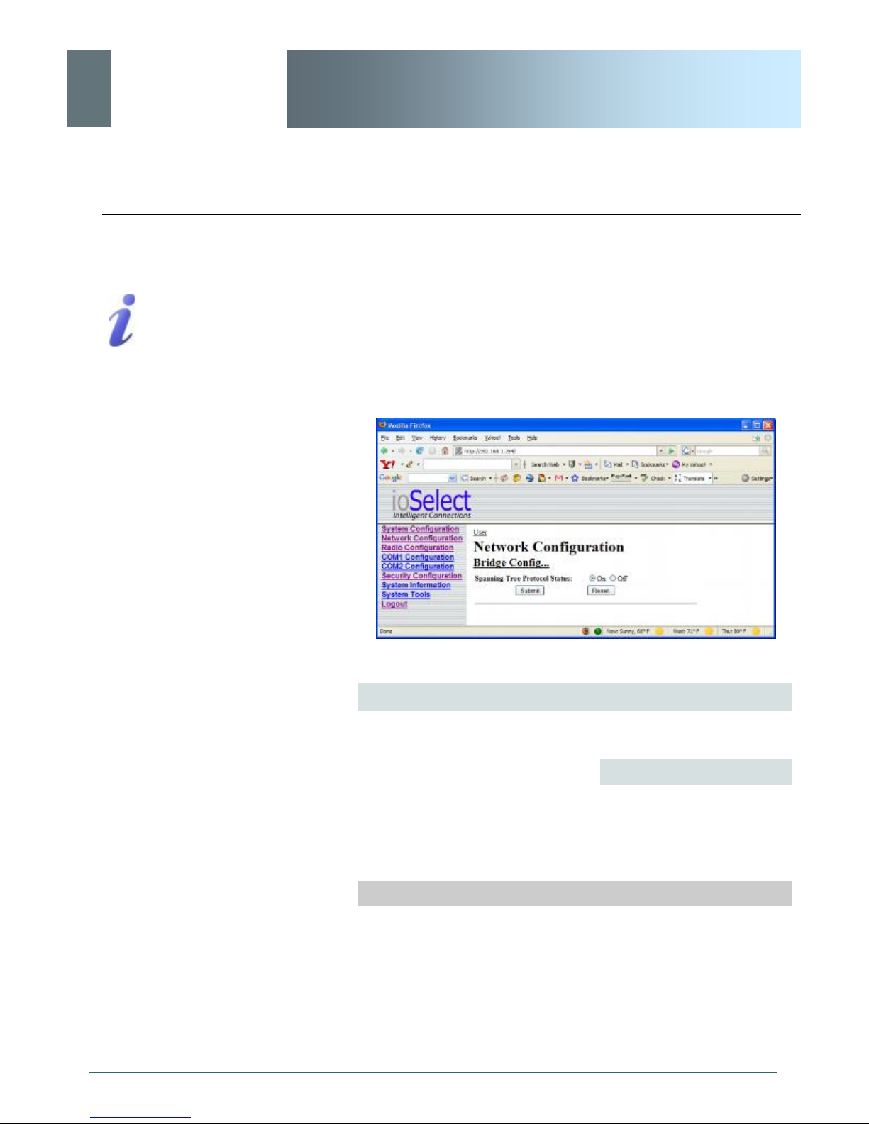
ioSelect
Soft Buttons
6.0 Configuration
STP: Spanning Tree Protocol
is a link management protocol
which will accommodate the
availability of redundant data
paths but inhibit the possibility
of a loop being created: a
loop could create endless
traffic ‘around’ a LAN,
consuming much of the
bandwidth.
EtherWave - WMR
6.1.4.5 Bridge Configuration
In most deployments, Spanning Tree Protocol (STP) will not be required. It does consume a small amount of bandwidth. The default
is ‘On’. If desired, change the status to ‘Off’.
Note that this menu item will not appear if the EtherWave-WMR unit
is configured to be a router.
Image 6L: Network Configuration, Bridge Config. Submenu
Spanning Tree Protocol Status
Selection of STP operational status within the EtherWave-WMR:
Values
On
On
Off
· Submit
Write parameter values into EtherWave-WMR memory.
· Reset
Restore ‘currently’ modified parameter values to those
which were previously written into EtherWave-WMR
memory.
© ioSelect Inc. CONFIDENTIAL 67
Page 68
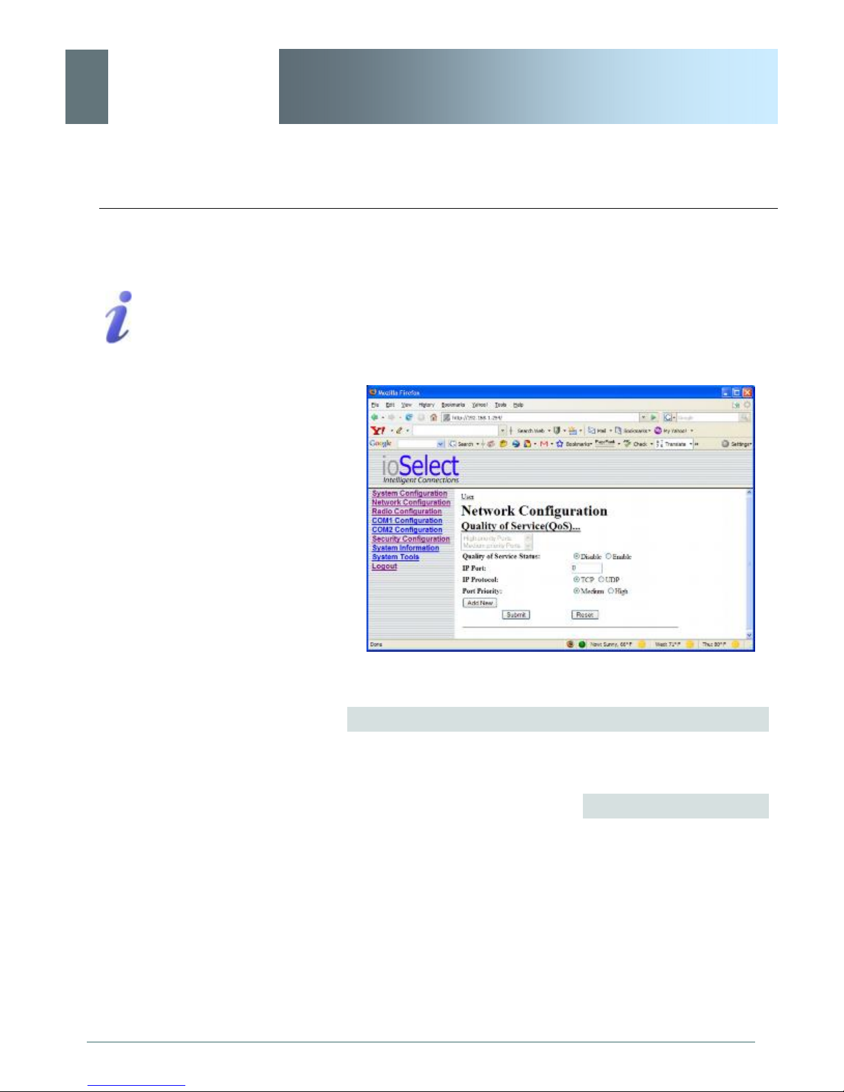
ioSelect
6.0 Configuration
QoS: Quality of Service is
applied to networks where it
is desired to give particular
data traffic/protocol(s) priority
over other data traffic.
EtherWave - WMR
6.1.4.6 Quality of Service
Quality of Service (QoS) may be applied to various data which enter
the EtherWave-WMR. This section describes configuring QoS for
data which enters via the ethernet port.
Image 6M: Network Configuration, Quality of Service Submenu
Quality of Service Status
If Enabled, the defined protocols and ports will have the QoS
service applied to them.
Values
Disable
Disable
Enable
To define particular ports, protocol, and priority to be assigned, see
the example of such a configuration exercise on the following page.
© ioSelect Inc. CONFIDENTIAL 68
Page 69
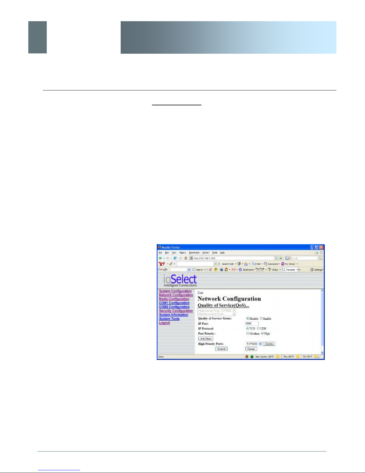
ioSelect
6.0 Configuration
EtherWave - WMR
Example 6.1.4.6.1
Assume that we want to add high priority to TCP traffic on Port
8080:
· In the IP Port field, enter 8080.
· Select the radio button for TCP.
· Select the radio button for High Priority.
· Click the ADD NEW soft button.
· Click the SUBMIT soft button.
The following screen capture shows the result of the above actions:
© ioSelect Inc. CONFIDENTIAL 69
Image 6N: Network Configuration, QoS Example
The mini window shows port 8080, TCP traffic, as having High
Priority. To apply the configuration: select Enable and SUBMIT.
As ports are defined, the mini window and list boxes (specific to
Priority) become populated. To DELETE any defined port, simply
select it via the appropriate list box and click the DELETE soft
button.
Page 70

ioSelect
Soft Buttons
6.0 Configuration
EtherWave - WMR
· Submit
Write parameter values into EtherWave-WMR memory.
· Reset
Restore ‘currently’ modified parameter values to those
which were previously written into EtherWave-WMR
memory.
© ioSelect Inc. CONFIDENTIAL 70
Page 71
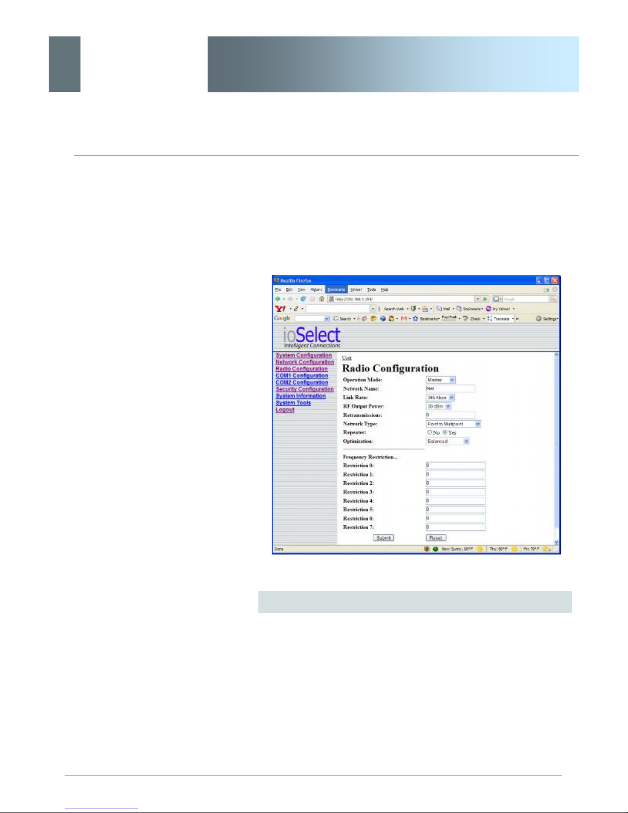
ioSelect
6.0 Configuration
EtherWave - WMR
6.1.5 Radio Configuration
The parameters within the Radio Configuration menu must be input
properly; they are the most basic requirement for radio network connectivity.
Prior to configuration, the network topology must be known (see Section 5.0); the role (operating mode) of the specific EtherWave-WMR
© ioSelect Inc. CONFIDENTIAL 71
Image 6O: Radio Configuration Menu (upper portion)
Network Search Mode
The above screen capture depicts Radio Configuration menu option
with Network Search Mode disabled. On the following page, the
screen capture shows what configuration options are available
when Network Search Mode is enabled.
continued...
Page 72
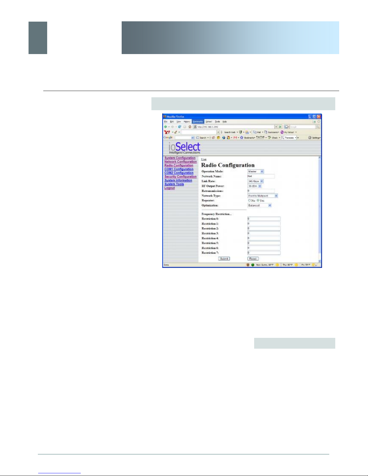
ioSelect
6.0 Configuration
EtherWave - WMR
Network Search Mode (continued)
Image 6P: Radio Configuration Menu (upper portion), with Network
Search Mode Enabled
With Network Search Mode enabled, Master units with the same
authentication key may be found by Remote units even if they have
different network names.
This feature, which must be enabled on all participating units,
allows for ‘roaming’ between networks.
Values
Disable
Disable
Enable
© ioSelect Inc. CONFIDENTIAL 72
Page 73

ioSelect
6.0 Configuration
EtherWave - WMR
Operation Mode
Select the mode of operation for the EtherWave-WMR: Master,
Repeater, or Remote. An EtherWave-WMR may be configured for
any role required within a radio network. This is convenient for
reasons of familiarity with any/all units, as well as for hardware
sparing purposes.
Master: Only one per network. For all Network Types data either
originates at, is destined to, or ‘passes through’ the Master.
The selected Operation Mode
will effect which configuration
options are presented.
i.e. There are settings which
apply to a Master which do
not apply, and are therefore
not presented, for a Remote.
Repeater: May act simply as a ‘Repeater’ to store and forward
data to/from an upstream unit to/from a downstream unit (e.g. when
there is a long distance between the latter units), or, may act as a
Repeater/Remote in which case the above function is performed
AND the unit may also exchange data as a Remote within the
network.
If 1 or more repeaters are to be in a network, on the Master (only)
the Repeater(s) YES configuration must be selected.
If 2 or more repeaters are to be in a network: the above ‘YES’
setting applies as does the requirement for Repeater Registration
(discussed further on in this section).
Remote: Interfaces with remote devices and communicates with
Master either directly or via Repeater(s). Communications between
2 or more Remotes is possible - through the Master - see
Network Types (further on in this section, and also refer to Section
5.3, 5.4).
Values
Remote
Master
Repeater
Remote
© ioSelect Inc. CONFIDENTIAL 73
Authentication Key
The Authentication Key is used to define the network search group:
Masters with the same key can be found by Remotes with different
Network Names.
continued...
Page 74

ioSelect
6.0 Configuration
Change the default value for
the Network Name to
something unique for your
network. Do this for an added
measure of security and to
differentiate your network
from others which may be
operating nearby.
EtherWave - WMR
Authentication Key (continued)
Values
Public
Character string
Network Name
All EtherWave-WMR in a given network must have the same
Network Namw. This unique network address is not only a security
feature for a particular network, but also allows other networks with their own unique network address - to operate in the same
area without the possibility of undesired data exchange between
networks.
Referring to the Network Profile configuration (detailed previously in
this section), the Network Name can also be used as the single
parameter to change when a Remote is to ’switch’ from operating
between distinct networks.
The Network Name is also taken into consideration in the frequency
hopping algorithm: change the Network Name and the hopping
pattern will change.
Values
default is model-dependent
character string
Link Rate
This is the RF communications Link Rate. A lower link rate offers
better receive sensitivity performance; a higher link rate, better
throughput. All EtherWave-WMR in a network must use the same
Link Rate.
Values
default value and available
rate(s) are model-dependent
© ioSelect Inc. CONFIDENTIAL 74
Page 75
ioSelect
6.0 Configuration
If the Operation Mode is set
to MASTER, the Unit Address
field will NOT be displayed in
the Radio Configuration
menu.
EtherWave - WMR
Unit Address
The unit address is, and must be, a unique identifier of each
modem in a network.
The Master has by default, and must retain, a unit address of 1;
65535 is the broadcast address.
Values
By setting the unit to Master,
its Unit Address will be 1.
FCC regulations allow for
up to 36dBi effective
isotropic radiated power
(EIRP). The sum (in dBm)
of the transmitted power,
the cabling loss, and the
antenna gain cannot
exceed 36dBi.
number varies
2-65534
RF Output Power
This setting establishes the transmit power level which will be
presented to the antenna connector at the rear of the EtherWaveWMR.
Unless required, the RF Output Power should be set not for
maximum, but rather for the minimum value required to maintain an
adequate system fade margin.
Values
dBm (mW equivalent)
20 (100)
21 (125)
22 (160)
23 (200)
24 (250)
25 (320)
26 (400)
27 (500)
28 (630)
29 (800)
30 (1000)
© ioSelect Inc. CONFIDENTIAL 75
Page 76

ioSelect
6.0 Configuration
In a PMP system, set
Retransmissions to the
minimum value required as,
effectively, the data
throughput from Master to
Remotes is divided by 1 plus
the Retransmissions value.
EtherWave - WMR
Retransmissions
This register determines the maximum amount of times that a
packet will be retransmitted (in addition to the initial transmission),
noting the following specific behaviours in various network
topologies:
PMP: Master will retransmit each data packet the exact number of
times specified in the Retransmissions field; Remote will retransmit
only if necessary, and then only until a given packet is
acknowledged or the value of the Remote’s Retransmissions field is
reached (after which it will discard the packet if retransmission not
successful). *See also ‘PMP with ACK” described in the Network
Type (below).
PTP: EtherWave-WMR will retransmit to its counterpart only if
necessary, and to a maximum number of the value specified in its
Retransmissions field. Packet is discarded if retransmissions are
not successful.
ALL modems in a network
must have the SAME value
for Network Type.
Values
0-255
5
Network Type
Defines the type of RADIO network (see Section 5.0 for a detailed
description of network topologies).
In a point-to-multipoint (PMP) network, the Master broadcasts data
to all units, and all remote units send their data (ultimately) to the
Master.
A point-to-point (PTP) network involves a Master and a Slave (with
0 or more Repeaters between them).
Peer-to-Peer (P2P) supports communication (through the Master)
between 2 (typically remote) units.
In an Everyone-to-Everyone (E2E) network, all units communicate
with all other units, through the Master. Note that this mode is very
bandwidth-intensive.
continued...
© ioSelect Inc. CONFIDENTIAL 76
Page 77

ioSelect
6.0 Configuration
Keep in mind that the
Network Type determines the
path that data will take.
i.e. In a PMP system, the
data flows from the Master to
Remotes, and from Remotes
to the Master. If a ping to
Remote B was sent to
Remote A, it will not arrive as
the data cannot travel from
Remote to Remote. Similarly,
a ping to a Repeater from a
Remote will not arrive either:
the destination for a Remote
in a PMP system is the
Master - not a Repeater, even
though it appears in the data
‘path’ to the Master.
EtherWave - WMR
Network Type (continued)
Point-to-Multipoint with ACK is a configuration whereby the Network
functions as a Point-to-Multipoint, but the Retransmissions behave
as a combination of PTP and PMP in that: If retransmissions are
set to 5 (for example) on the Master, and the packets it sends to the
Remotes result in an ACK being received by each of the Remotes
in the network, the Master will not send the data again (refer to the
PMP behavior described in the preceding Retransmissions section).
If, however, the Master does NOT receive an ACK from all
Remotes in the network, it will then revert to sending the data
again, to the maximum number of Retransmissions specified, for a
period of one minute, after which time it will revert to behaving as it
did originally.
This mode of operation is particularly well-suited to fixed PMP
networks when multipoint operation is required as is maximum
throughput.
The selected Network Type will effect the Radio Configuration
menu somewhat, i.e. If Point-to-Multipoint is selected for a Remote,
there is no menu item for a Destination Address as the destination
is - must be - the Master (Unit Address 1).
Values
Point-to-Multipoint
Point-to-Point
Peer-to-Peer
Everyone-to-Everyone
PMP with ACK
© ioSelect Inc. CONFIDENTIAL 77
Page 78

ioSelect
6.0 Configuration
EtherWave - WMR
Destination Unit
As the name implies, this register specifies the ultimate destination
for an EtherWave-WMR’s data. Different network topologies dictate
the configuration of the Destination Unit (address):
For a Remote in a Point-to-Multipoint network, this menu option will
not appear: by definition, the destination is the Master (UA = 1).
For the Master in PMP, its Destination Unit (Address) is 65535—the
broadcast address as it sends its data to all points.
In a Point-to-Point configuration, the destination is to be specified
(for a Remote: the Master); in the Master’s Radio Configuration,
specify the Unit Address of the Remote Unit to which it is to send its
data.
In Peer-to-Peer, the Remotes are configured with the target peer’s
UA as the Destination Address, the Master with 65535; in
Everyone-to-Everyone, the Destination Address for ALL units is
65535 - the broadcast address - as every unit sends its data to
every other unit (through the Master). E2E is a very bandwidth
intensive network topology.
Values
1-65535
Tx Control
This configuration option does not apply to a Master EtherWaveWMR.
On (the default) permits the EtherWave-WMR to transmit, i.e. RF
emissions are enabled.
Off configures the EtherWave-WMR for RECEIVE ONLY. If ‘Off’ is
selected, ‘On’ may only be selected LOCALLY or via a special UDP
packet sent from the DiscoverIP Utility.
© ioSelect Inc. CONFIDENTIAL 78
Values
On
Off
Page 79

ioSelect
6.0 Configuration
When bench testing 3
EtherWave-WMR for a
Master-Repeater-Remote
link, be sure to set the
Remote’s Roaming Address
to the Unit Address (UA) of
the Repeater, and the
Repeater’s Roaming Address
to the UA (1) of the Master.
EtherWave - WMR
Roaming Address
This feature allows a Remote unit to synchronize with a specified
‘upstream’ unit (either Master or Repeater). The options are as
follows:
65535: With this value as its Roaming Address, a Remote will
synchronize with an upstream unit which has the same Network
Name as the Remote. Should that upstream unit fail, this Remote
will attempt to synchronize with another ’upstream’ unit within the
same network (i.e. same Network Name). This ability is particularly
well-suited to mobile applications.
1-254: In most static (fixed) networks, where there are no
Repeaters, the default value of 1 is maintained: All Slaves
synchronize to the Master (whose unit address is 1).
This will ensure that data is
routed from the Remote
through the Repeater to the
Master; otherwise, if the
Remote’s Roaming Address
is left at the default value of 1,
the Remote will communicate
directly with the Master,
bypassing the Repeater
altogether.
In networks where Repeaters are present, the value of a Remote’s
Roaming Address typically corresponds to the particular upstream
modem with which a particular Remote is intended to communicate,
e.g. Slave with Unit Address 3 may have a Roaming Address of 2,
where the modem with Unit Address 2 is a Repeater between the
Slave and the Master; the Repeater will have a Roaming Address
of 1 as it is to synchronize to the Master.
The Roaming Address dictates to which EtherWave-WMR (by Unit
Address (UA)) a Remote (or Repeater) will ’look’ or ’attach to’ for its
upstream signal path.
See the description of Network Profile earlier in this section for
more information about roaming-type options. The Network Profile
allows for roaming between networks whereas the Roaming
Address provides for roaming within a network.
Values
65535 full roaming
1-254 specific (fixed) unit
address (Master or
Repeater) with which to
associate
© ioSelect Inc. CONFIDENTIAL 79
1
Page 80

ioSelect
6.0 Configuration
EtherWave - WMR
Repeater
This setting applies to the Master only.
The default value is No, stating there are no Repeaters in the
network.
With one or more Repeaters
in the system, a network’s
throughput is divided in half.
Exercising the option of backto-back ‘Repeaters’ - which
requires 2 EtherWave-WMR
at a ‘Repeater’ site eliminates the division of
bandwidth.
If there is more than one
Repeater in a network, the
Repeaters should be
‘registered’. See ‘Repeater
Registration’ further along in
this section re how to
accomplish this.
If there are 1 or more Repeaters in the network, configure this
setting as Yes.
Values
No
Yes
© ioSelect Inc. CONFIDENTIAL 80
Page 81

ioSelect
6.0 Configuration
EtherWave - WMR
Optimization
This setting applies to the Master only.
‘Balanced’ is the default setting and is typically the best choice for
‘Optimization’. The other options are High Throughput (when
throughput is a priority) and Low Latency (best suited to small
packets).
Optimization is a trade-off between throughput and latency.
Values
High Throughput
Balanced
Low Latency
Zone Restriction
Zone restriction dictates within which band (zone) of frequencies
that a particular unit will operate.
Using zones simplifies network deployment by providing a
convenient reference (e.g. Zone 1) within which a given network
can operate, thereby minimizing the potential for internetwork
interference. This is particularly useful when used in conjunction
with Network Search Mode to facilitate minimal interference among
adjacently deployed networks.
The tables on the following page illustrate the various zones and
their associated frequency restrictions. Note that there is a
difference between zone ‘values’ depending on the Wireless Link
Rate selected.
continued…
© ioSelect Inc. CONFIDENTIAL 81
Page 82
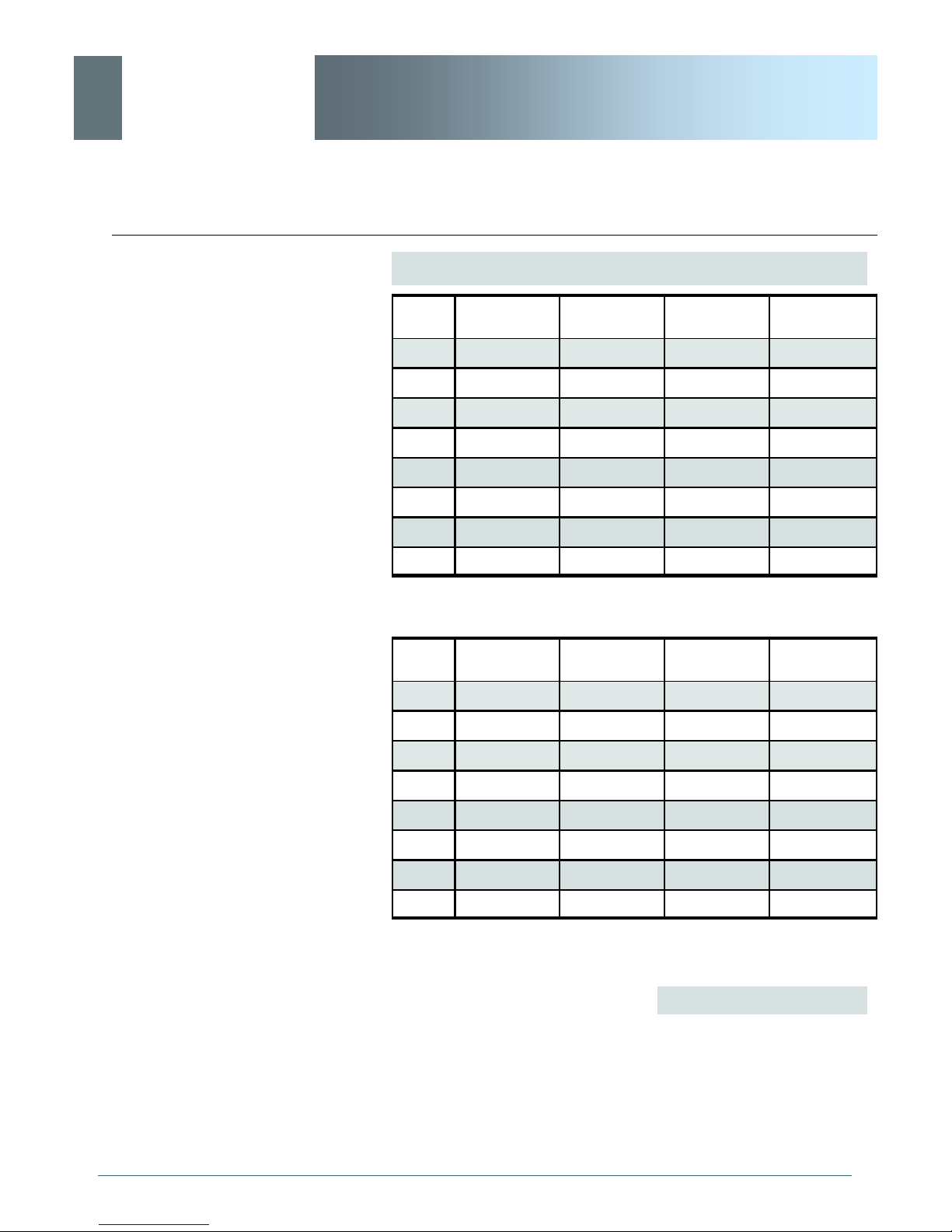
ioSelect
6.0 Configuration
EtherWave - WMR
Zone Restriction (continued)
Zone
No.
Zone
No.
Restrict From
Start (MHz)
1 923.200 927.600
2 902.400 902.800 924.000 927.600
3 902.400 903.600 924.800 927.600
4 902.400 904.400 925.600 927.600
5 902.400 905.200 926.400 927.600
6 902.400 906.000 927.200 927.600
7 902.400 906.800
8 912.800 917.200
Table 6A: Restricted Bands for UA1 at 345kbps Link Rate
Restrict From
Start (MHz)
1 909.750 926.250
2 902.400 905.250 912.750 926.250
3 902.400 908.250 915.750 926.250
Restrict To
End (MHz)
Restrict To
End (MHz)
Restrict From
Start (MHz)
Restrict From
Start (MHz)
Restrict to
End (MHz)
Restrict to
End (MHz)
© ioSelect Inc. CONFIDENTIAL 82
4 902.400 911.250 918.750 926.250
5 902.400 914.250 921.750 926.250
6 902.400 917.250 924.750 926.250
7 902.400 920.250
8 906.750 923.250
Table 6B: Restricted Bands for UA1 at 1.1Mbps Link Rate
Values
None
Zone 1, 2, 3, 4, 5, 6, 7, and 8
Page 83

ioSelect
6.0 Configuration
EtherWave - WMR
Channel Number
This setting applies only if the Link Rate is set to 1.1Mbps.
Channel Number defines the number of channels the unit will hop
on. The minimum number is 4. (Digital Transmission System
(DTS) technology is applied at the 1.1Mbps link rate.)
(This setting does not apply if the Link Rate is 345kbps because of
the 64 channels that are available, the unit must hop on exactly 50 there is not option to either increase or decrease this amount.)
Values
4-16
16
© ioSelect Inc. CONFIDENTIAL 83
Page 84
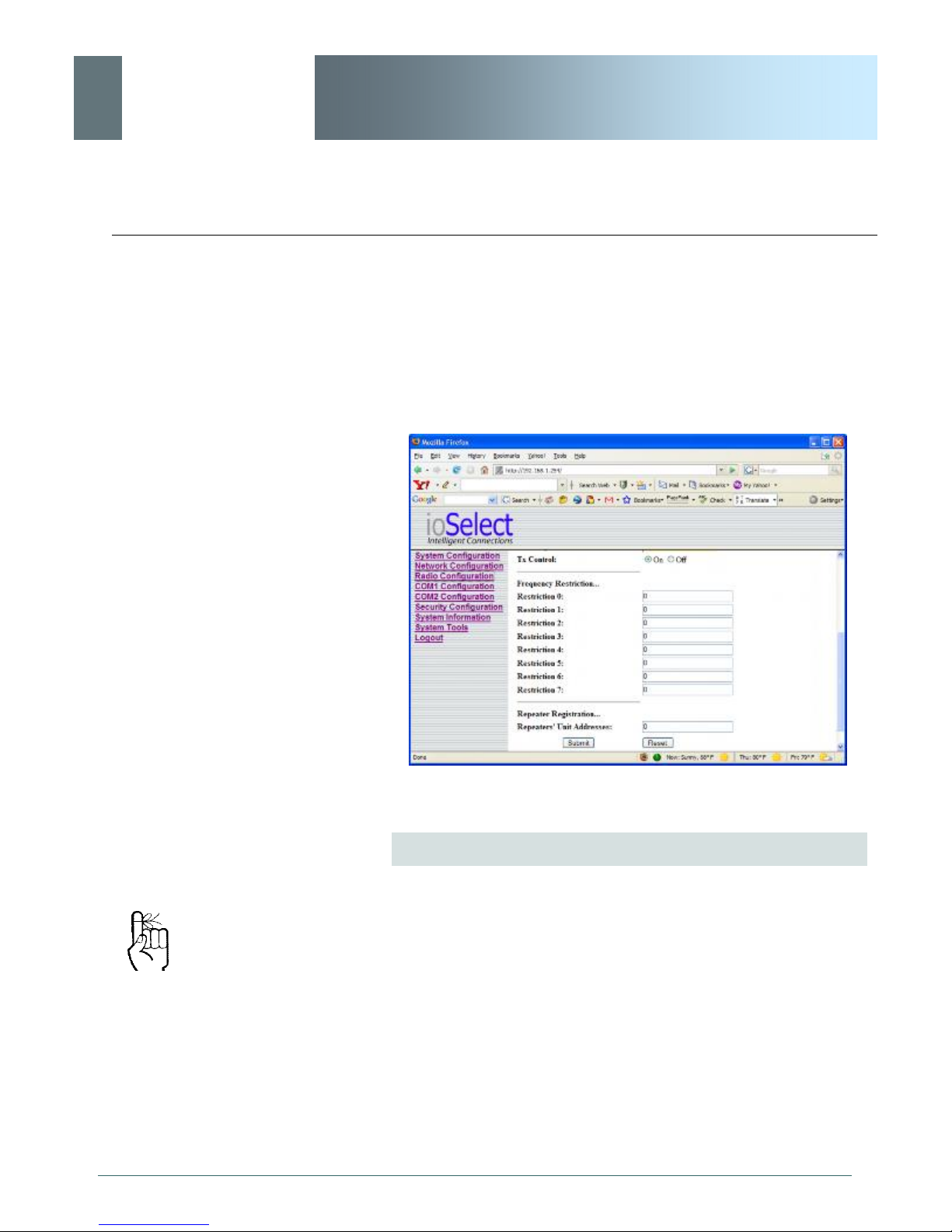
ioSelect
6.0 Configuration
EtherWave - WMR
Scrolling down the Radio Configuration menu reveals further
configuration options: Frequency Restriction and Repeater
Registration. Typically the former is not required; the latter only
applies if there are 2 or more Repeaters in your network.
All modems in the network
must have the same frequency
restriction configured within
them.
© ioSelect Inc. CONFIDENTIAL 84
Image 6Q: Radio Configuration Menu (lower portion)
Frequency Restriction
By default, the EtherWave-WMR will hop on frequencies across the
entire 902-928MHz ISM band. For some applications or within
certain operating environments it may be desired to prohibit the
modem from operating on specific frequencies or range(s) of
frequencies.
(See Section 6.1.8.4 for a description of the Radio Channel Noise
Levels tool.)
The modem will not allow ‘too many’ frequencies to be restricted; it
requires a certain amount of bandwidth within which to operate to
comply with regulations.
Page 85
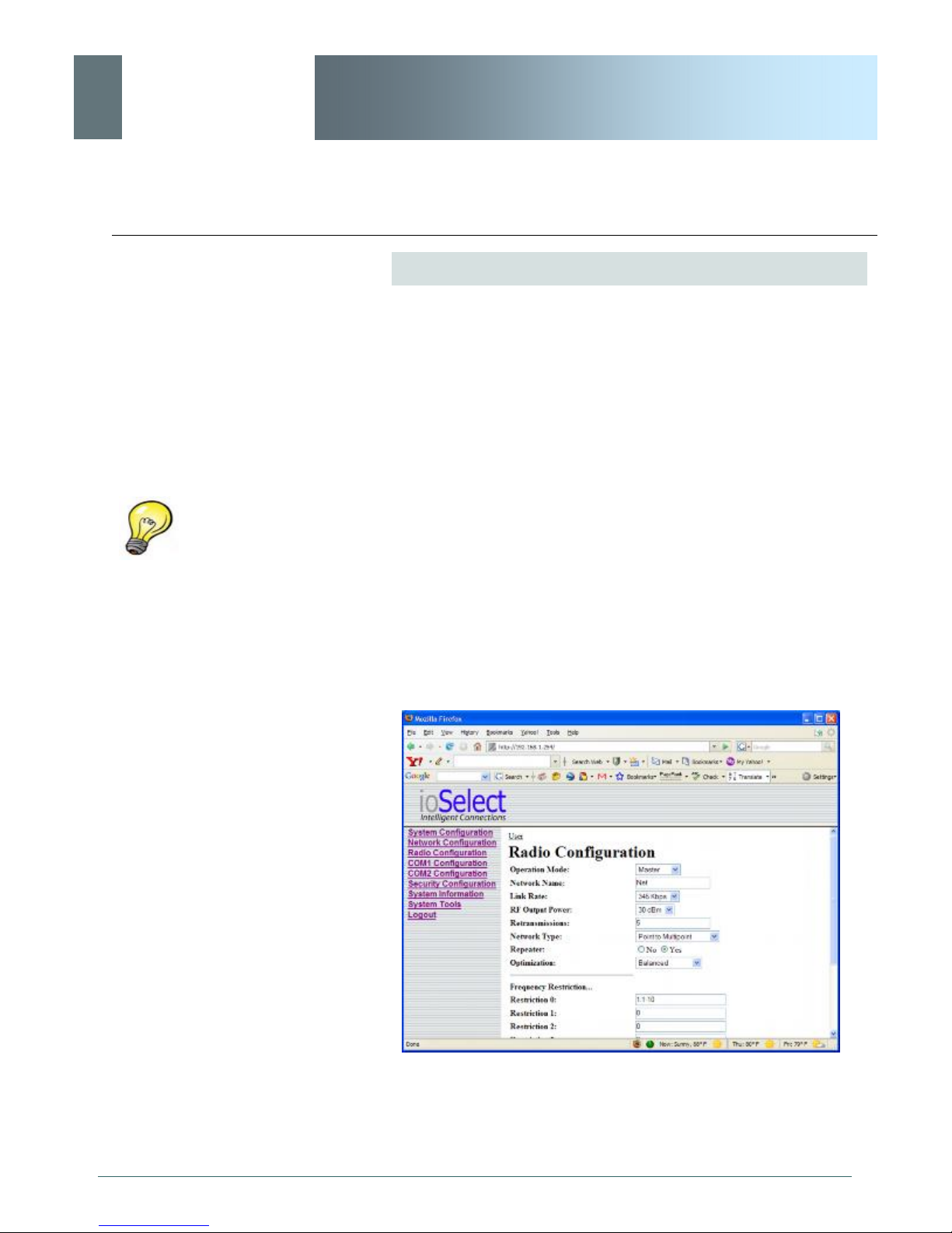
ioSelect
6.0 Configuration
Use the Radio Channels Noise
Level tool (see Section 6.1.8.4)
to help identify the frequency/
range of possible interfering
signals within the 902-928MHz
ISM band, and then use the
Frequency Restriction feature
to configure the EtherWaveWMR to avoid them.
EtherWave - WMR
Frequency Restriction (continued)
The input format is:
UA: channel number, or
UA: channel number-channel number z, or
UA: channel number,<no space>chnl number-chnl number
where UA is the Unit Address, and
channel number is the channel number (not frequency) of
the channel to be restricted.
The input formats above describe single channel, range of
channels, or a combination thereof. A number of input fields may
be used, or a combination of restrictions input in one field.
The image below shows an example of configuring an EtherWaveWMR (with 345kbps as an available Link Rate) with a Link Rate of
345kbps to not operate on channels 1 through 10.
© ioSelect Inc. CONFIDENTIAL 85
Image 6R: Frequency Restriction, 345kbps
Page 86
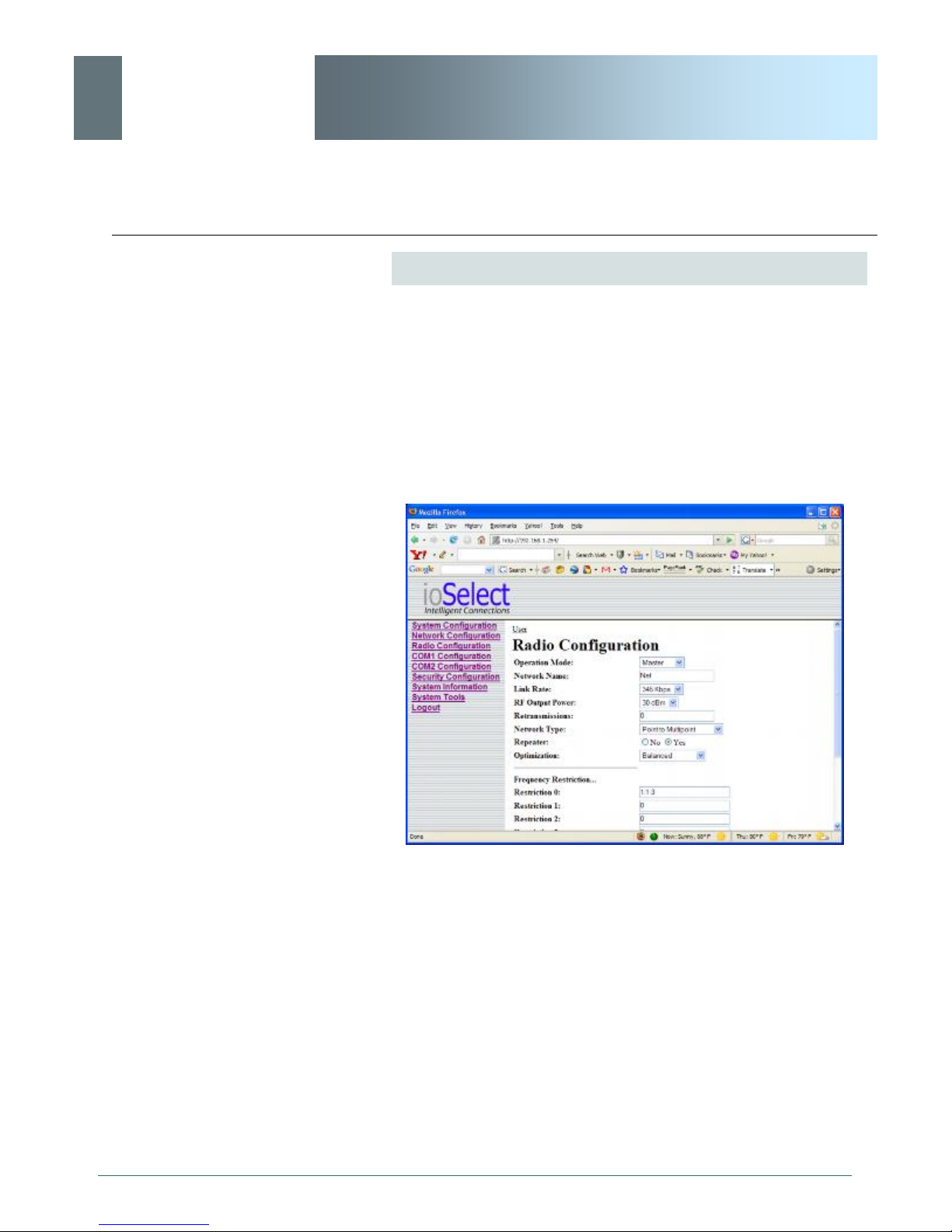
ioSelect
6.0 Configuration
EtherWave - WMR
Frequency Restriction (continued)
With the EtherWave-WMR having the option of, and configured for,
a Link Rate of 1.1Mbps (Special Order Only), the Frequency
Restriction input format remains the same (as for 345kbps
described previously), however, the Channel Number must be
reduced by the number of channels restricted, i.e. If Channels 1-3
are restricted, the Channel Number is to be decreased from 16 to
13, as per the following example (image below):
© ioSelect Inc. CONFIDENTIAL 86
Image 6S: Frequency Restriction, 1.1Mbps
The Frequency Restriction ‘value’ must be input into EVERY
MODEM in a network. Oftentimes the applicable Unit Address (as
input in the format detailed previously) will be ‘1’ - indicating that
that the Master modem - to which other units synchronize - will not
be transmitting on the specified channel(s). All units in the system
will use this information - as input into each one of them - to
generate the appropriate hopping pattern for the network.
Page 87
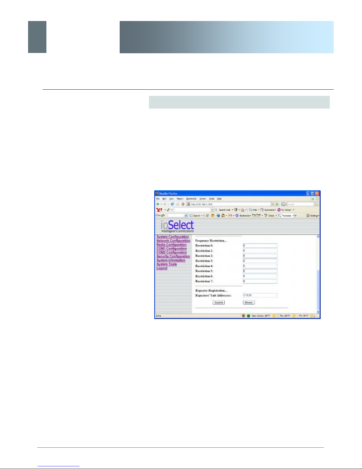
ioSelect
6.0 Configuration
EtherWave - WMR
Repeater Registration
In order to ensure that generated hopping patterns are orthogonal
to each other (thereby minimizing possible interference between
network segments), if there is more than 1 Repeater in a network,
ALL Repeaters must be registered in EVERY EtherWave-WMR.
The following image depicts an example:
© ioSelect Inc. CONFIDENTIAL 87
Image 6T: Repeater Registration
In the above example, there is a total of 3 Repeaters in the system,
with Unit Addresses of 7, 18, and 25. Again, these Repeater UAs
must be added into each/every EtherWave-WMR’s Repeater
Registration field.
Format:
x,y,z
where
x, y, and z are Repeater UAs,
Page 88

ioSelect
6.0 Configuration
EtherWave - WMR
Soft Buttons
· Submit
Write parameter values into EtherWave-WMR memory.
· Reset
Restore ‘currently’ modified parameter values to those
which were previously written into EtherWave-WMR
memory.
© ioSelect Inc. CONFIDENTIAL 88
Page 89
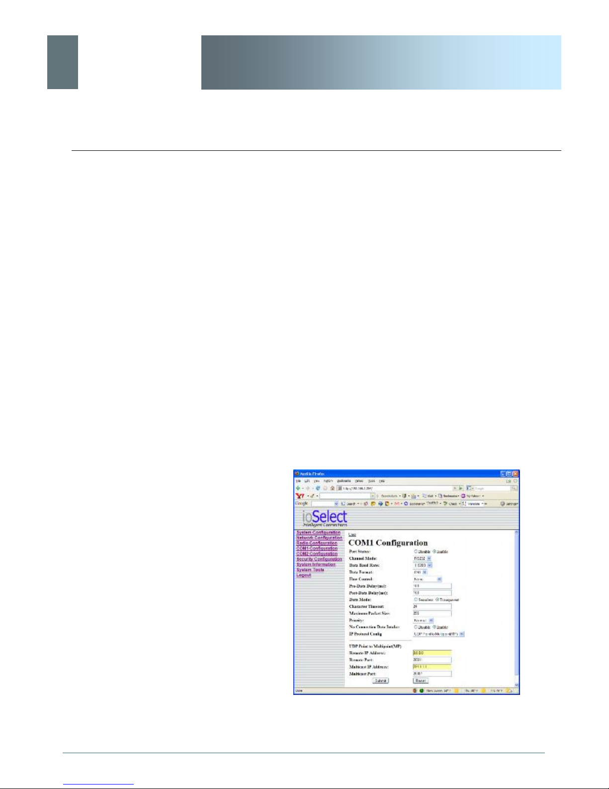
ioSelect
6.0 Configuration
EtherWave - WMR
6.1.6 COM1 and COM2 Configuration
The menus ’COM1 Configuration’ and ’COM2 Configuration’ are
used to configure the serial device server for the serial
communications ports:
· COM1, the rear DE9 connector on the EtherWave-
WMR, and
· COM2, the front RJ45 connector, respectively.
Serial device data may be brought into a LAN network through
TCP, UDP, or multicast; it may also exit the EtherWave-WMR
network on another EtherWave-WMR’s serial port.
COM1 is a full-featured RS232 interface dedicated to serial data
traffic. It supports hardware handshaking. By default, this port is
enabled.
COM2 is, by default, disabled. In this state, it may be used as the
console port for the text user interface. Enabled, it becomes
another serial port for data traffic. It is a 3-wire (TxD, RxD, and SG)
interface and does not support hardware handshaking.
For brevity, only COM1 is fully detailed in this section; the relative
limitations of COM2 are noted where applicable.
© ioSelect Inc. CONFIDENTIAL 89
Image 6U: COM1 Configuration Menu (upper portion)
Page 90
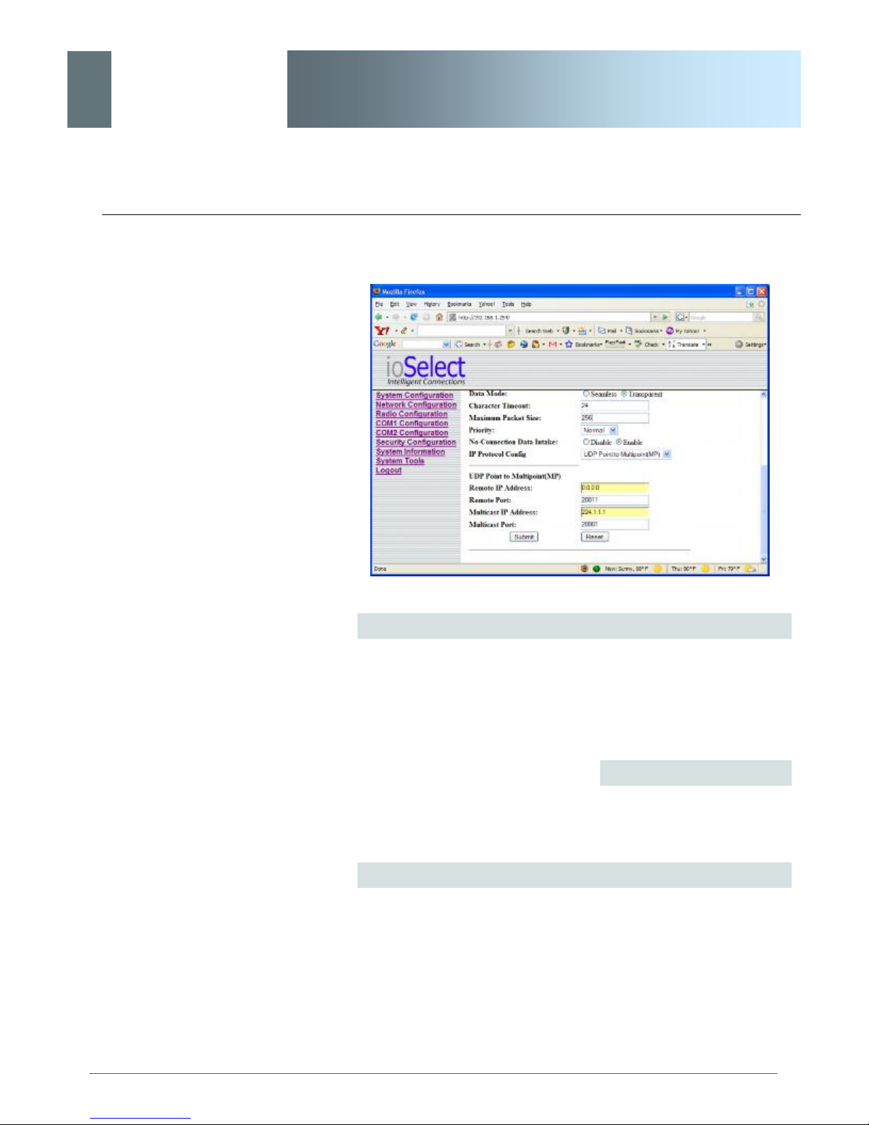
ioSelect
6.0 Configuration
EtherWave - WMR
Image 6V: COM1 Configuration Menu (lower portion)
Port Status
Select operational status of port. Enabled by default.
*COM2 is Disabled by default. If COM2 is Enabled and there is a
desire to switch it back to Disabled (console mode) via the serial
connection to it, the escape sequence of ‘+++’ may be entered at
the Data Baud Rate for which the port is configured.
Values
Enable
Disable
Channel Mode
Determines which (rear of unit) serial interface shall be used to
connect to external devices: RS232, RS485, or RS422. This
option applies only to COM1. When an interface other than RS232
is selected, the DE9 port will be inactive.
*COM2 is RS232 only, 3-wire (TxD, RxD, and SG).
...continued
© ioSelect Inc. CONFIDENTIAL 90
Page 91

ioSelect
6.0 Configuration
EtherWave - WMR
Channel Mode (continued)
Values
RS232
RS485
RS422
Data Baud Rate
The serial baud rate is the rate at which the modem is to
communicate with the attached local asynchronous device.
*COM2 data baud rate maximum is 115200bps.
Values
Note: Most PCs do not
readily support serial
communications greater than
115200bps.
bits per second (bps)
230400
115200
57600
38400
28800
19200
14400
9600
460800 and 921600 may be
selected for RS422 or
RS485 Channel Modes.
7200
4800
3600
2400
1200
600
300
Data Format
This setting determines the format of the data on the serial port.
The default is 8 data bits, No parity, and 1 Stop bit.
Values
8N1
8N2
8E1
8O1
7N1
7N2
7E1
7O1
7E2
7O2
© ioSelect Inc. CONFIDENTIAL 91
Page 92
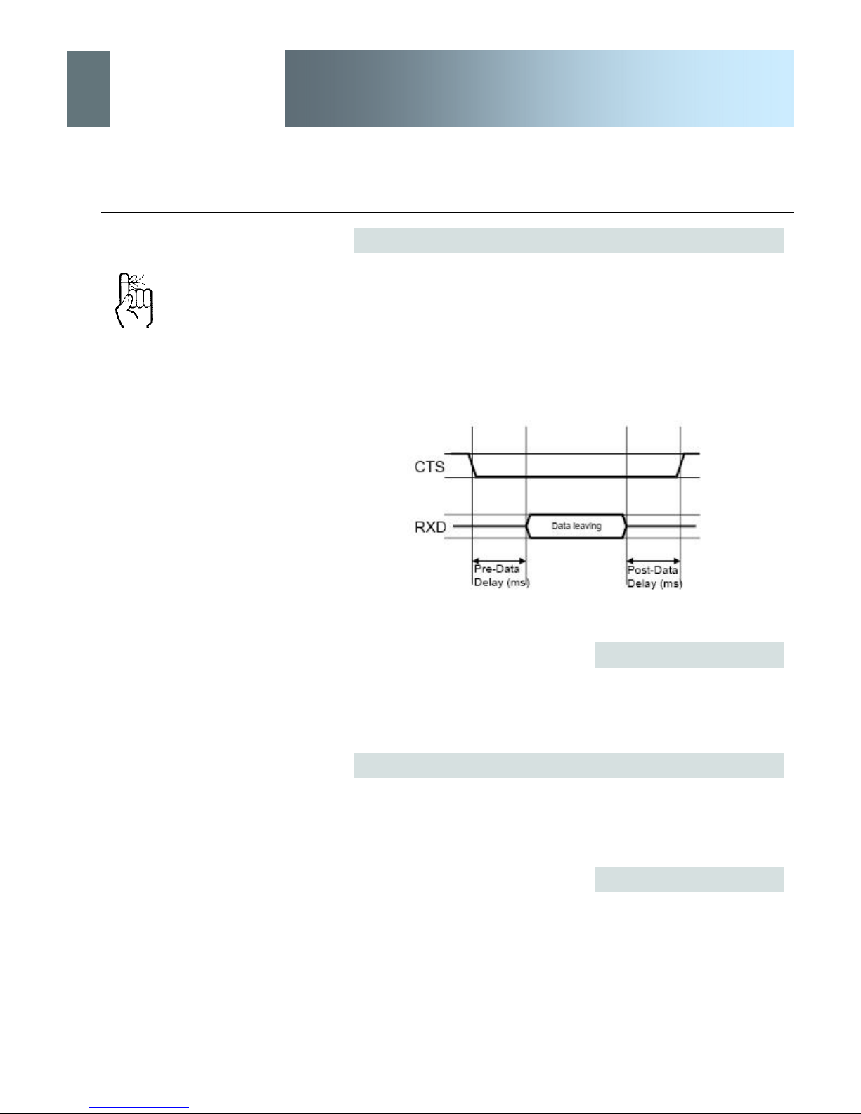
ioSelect
6.0 Configuration
EtherWave - WMR
Flow Control
Flow control may be used to enhance the reliability of serial data
communications, particularly at higher baud rates. If the attached
device does not support hardware handshaking, leave this setting
at the default value of ‘None’.
Software flow control (XON/
XOFF) is not supported.
When CTS Framing is selected, the EtherWave-WMR uses the
CTS signal to gate the output data on the serial port. Figure 6A
below illustrates the timing of framed output data.
*COM2 does not support Flow Control.
Drawing 6A: CTS Output Data Framing
Values
None
Hardware
CTS Framing
© ioSelect Inc. CONFIDENTIAL 92
Pre-Data Delay (ms)
Refer to Figure b on the preceding page.
*COM2 does not support this function.
Values
ms
100
Page 93

ioSelect
6.0 Configuration
EtherWave - WMR
Post-Data Delay (ms)
Refer to Figure b on the preceding page.
*COM2 does not support this function.
Values
ms
100
Data Mode
This setting defines the serial output data framing.
In Transparent mode (default), the received data will be output
promptly from the EtherWave-WMR.
When set to Seamless, the serial port server will add a gap
between data frames to comply with the MODBUS protocol for
example. See ‘Character Timeout’ on the next page for related
information.
Values
Seamless
Transparent
Character Timeout
In Seamless mode (see Data Mode described on the preceding
page), this setting determines when the serial server will consider
the recently-received incoming data as being ready to transmit. As
per the MODBUS standard, frames will be marked as ‘bad’ if the
time gap between frames is greater than 1.5 characters, but less
than the Character Timeout value.
© ioSelect Inc. CONFIDENTIAL 93
The serial server also uses this parameter to determine the time
gap inserted between frames. It is measured in ‘characters’ and
related to baud rate.
continued...
Page 94

ioSelect
6.0 Configuration
EtherWave - WMR
Character Timeout (continued)
Example: If the baud rate is 9600bps, it takes approximately 1ms
to move one character. With the Character Timeout set to 4, the
timeout period is 4ms. When the calculated time is less than
3.5ms, the serial server will set the character timeout to a minimum
value of 3.5ms.
If the baud rate is greater than 19200bps, the minimum character
timeout is internally set to 750us (microseconds).
Values
characters
4
Maximum Packet Size
Defines the buffer size that the serial server will use to receive data
from the serial port. When the server detects that the Character
Timeout criteria has been met, or the buffer is full, it packetizes the
received frame and transmits it.
Values
Bytes
1024
Priority
This setting effects the Quality of Service (QoS) associated with the
data traffic on the specific COM port.
Values
© ioSelect Inc. CONFIDENTIAL 94
Normal
Medium
High
Page 95

ioSelect
6.0 Configuration
EtherWave - WMR
IP Protocol Config
This setting determines which protocol the serial server will use to
transmit serial port data over the EtherWave-WMR network.
The protocol selected in the
IP Protocol Config field will
determine which configuration
options appear in the
remainder of the COMn
Configuration Menu.
UDP: User Datagram
Protocol does not provide
sequencing information for
the packets sent nor does it
establish a
’connection’ (‘handshaking’)
and is therefore most suited
to communicating small
packets of data.
TCP: Transmission Control
Protocol in contrast to UDP
does provide sequencing
information and is connectionoriented; a more reliable
protocol, particularly when
large amounts of data are
being communicated.
Requires more bandwidth
than UDP.
TCP Client: When TCP Client is selected and data is received on
its serial port, the EtherWave-WMR takes the initiative to find and
connect to a remote TCP server. The TCP session is terminated by
this same unit when the data exchange session is completed and
the connection timeout has expired. If a TCP connection cannot be
established, the serial port data is discarded.
· Remote Server Address
IP address of a TCP server which is ready to
accept serial port data through a TCP connection.
For example, this server may reside on a LAN
network server.
Default: 0.0.0.0
· Remote Server Port
A TCP port which the remote server listens to,
awaiting a session connection request from the
TCP Client. Once the session is established, the
serial port data is communicated from the Client to
the Server.
Default: 20001
· Outgoing Connection Timeout
This parameter determines when the EtherWaveWMR will terminate the TCP connection if
the connection is in an idle state (i.e. no data traffic
on the serial port).
Default: 60 (seconds)
TCP Server: In this mode, the EtherWave-WMR will not INITIATE
a session, rather, it will wait for a Client to request a session of it
(it’s being the Server—it ‘serves’ a Client). The unit will ‘listen’ on a
specific TCP port. If a session is established, data will flow from the
Client to the Server, and, if present, from the Server to the Client. If
a session is not established, both Client-side serial data, and
Server-side serial data , if present, will be discarded.
· Local Listening Port
The TCP port which the Server listens to. It allows
a TCP connection to be created by a TCP Client to
carry serial port data.
Default: 20001
continued...
© ioSelect Inc. CONFIDENTIAL 95
Page 96

ioSelect
6.0 Configuration
A UDP or TCP port is an
application end-point. The IP
address identifies the device
and, as an extension of the IP
address, the port essentially
‘fine tunes’ where the data is
to go ‘within the device’.
Be careful to select a port
number that is not
predetermined to be
associated with another
application type, e.g. HTTP
uses port 80.
EtherWave - WMR
IP Protocol Config (continued)
· Incoming Connection Timeout
Established when the TCP Server will terminate the
TCP connection is the connection is in an idle
state.
Default: 300 (seconds)
© ioSelect Inc. CONFIDENTIAL 96
TCP Client/Server: In this mode, the EtherWave-WMR will be a
combined TCP Client and Server, meaning that it can both initiate
and serve TCP connection (session) requests. Refer to the TCP
Client and TCP Server descriptions and settings described
previously as all information, combined, is applicable to this mode.
continued...
Page 97

ioSelect
6.0 Configuration
EtherWave - WMR
IP Protocol Config (continued)
UDP Point-to-Point: In this configuration the EtherWave-WMR will
send serial data to a specifically-defined point, using UDP packets.
This same EtherWave-WMR will accept UDP packets from that
same point.
· Remote IP Address
IP address of distant device to which UDP packets
are sent when data received at serial port.
Default: 0.0.0.0
· Remote Port
UDP port of distant device mentioned above.
Default: 20001
· Listening Port
UDP port which the EtherWave-WMR listens to
(monitors). UDP packets received on this port
are forwarded to the unit’s serial port.
Default: 20001
Multicast is a one-to-many
transmission of data over an
IP network. It is an efficient
method of transmitting the
same data to many recipients.
The recipients must me
members of the specific
multicast group.
TTL: Time to Live is the
number of hops a packet can
travel before being discarded.
In the context of multicast, a
TTL value of 1 restricts the
range of the packet to the
same subnet.
UDP Point-to-Multipoint (P): This mode is configured on an
EtherWave-WMR which is to send multicast UDP packets; typically,
the MASTER in the EtherWave-WMR network.
· Multicast IP Address
A valid multicast address this unit uses to send
multicast UDP packets upon receiving data from
the serial port. The default value is a good
example of a valid multicast address.
Default: 224.1.1.1
· Multicast Port
A UDP port that this EtherWave-WMR will send
UDP packets to. The Multipoint (MP - see the UDP
Point-to-Multipoint (MP) description) stations
should be configured to listen to this point in order
to receive multicast packets from this EtherWaveWMR.
Default: 20001
· Listening Port
The UDP port that this unit receives incoming data
on from multiple remote units.
Default: 20011
· Time to Live
Time to live for the multicast packets.
© ioSelect Inc. CONFIDENTIAL 97
Page 98

ioSelect
6.0 Configuration
In a Point-to-Multipoint (PMP)
network topology which is to
utilize UDP multicast, typically
the MASTER would be
configured as ’(P)’ (the
POINT) and the REMOTES
would be configured as
’(MP)’ (the MULTIPOINTS).
EtherWave - WMR
IP Protocol Config (continued)
UDP Point-to-Multipoint (MP): This protocol is selected on the
units which are to receive multicast UDP packets, typically the
Remote units. See the previous description of UDP Point-toMultipoint (P).
· Remote IP Address
The IP address of a distant device (EtherWaveWMR or, for example, a PC) to which the unit
sends UDP packets of data received on the serial
port. Most often this is the IP address of the
Master EtherWave-WMR.
Default: 0.0.0.0
· Remote Port
The UDP port associated with the Remote IP
Address (above). In the case of this ‘Remote’
being the Master EtherWave-WMR, the value in
this field should match the Listening Port of the
Master (see UDP Point-to-Multipoint (P)).
Default: 20011
· Multicast IP Address
A valid MULTICAST address that this unit will use
to receive multicast UDP packets sent by a UDP
Point-to-Multipoint (P) unit. Note that the default
value for this field matches the def ault Multicast IP
Address of the UDP Point-to-Multipoint (P)
configuration described on the previous page.
Default: 224.1.1.1
· Multicast Port
The UDP port that this unit will use, along with the
Multicast IP Address detailed above, to receive the
multicast UDP packets sent by the UDP Point-toMultipoint (P) unit.
Default: 20001
© ioSelect Inc. CONFIDENTIAL 98
Page 99

ioSelect
6.0 Configuration
EtherWave - WMR
IP Protocol Config (continued)
UDP Multipoint-to-Multipoint
· Multicast IP Address
A valid multicast address the unit will use to send
multicast UDP packets upon receiving them at its
serial port.
Default: 224.1.1.1
· Multicast Port
UDP port that the packets are sent to. Multipoint
stations should be configured to listen to this port in
order to receive multicast packets.
Default: 20011
· Time to Live
Time to live for the multicast packets.
Default: 1 (hop)
SMTP: Simple Mail Transport
Protocol is a protocol used to
transfer mail across an IP
network.
· Listening Multicast IP Address
A valid multicast address the unit is to listen to
receive multicast UDP packets sent by another
UDP Multipoint-to-Multipoint unit.
Default: 224.1.1.1
· Listening Multicast Port
UDP port that the unit will listen to for multicast
UDP packets sent by another UDP Multipoint-toMultipoint unit.
Default: 20011
SMTP Client: If the EtherWave-WMR network has Internet access,
this protocol may be used to send the data received on the serial
port (COM1), in a selectable format (see Transfer Mode (below)), to
an e-mail addressee. Both the SMTP Server and the e-mail
addressee must be ‘reachable’ for his feature to function.
· Mail Subject
Enter a suitable ‘e-mail subject’ (e-mail heading).
Default: COM1 Message
· Mail Server (IP/Name)
IP address or ‘Name’ of SMTP (Mail) Server.
Default: 0.0.0.0
continued...
© ioSelect Inc. CONFIDENTIAL 99
Page 100

ioSelect
Soft Buttons
6.0 Configuration
EtherWave - WMR
IP Protocol Config (continued)
· Mail Recipient
A valid e-mail address for the intended addressee,
entered in the proper format.
Default: host@
· Message Max Size
Maximum size for the e-mail message.
Default: 1024
· Timeout (s)
How long the unit will wait to gather data from the
serial port before sending an e-mail message; data
will be sent immediately upon reaching Message
Max Size.
Default: 10
· Transfer Mode
Select how the data received on COM1 is to be
sent to the email addressee. Options are: Text,
Attached File, Hex Code.
Default: Text
Note: COM2 does not support this mode.
Values
TCP Client
TCP Server
TCP Client/Server
UDP Point-to-Point
UDP Point-to-Multipoint (P)
UDP Point-to-Multipoint(MP)
UDP Multipoint-to-Multipoint
SMTP Client
· Submit
Write parameter values into EtherWave-WMR memory.
© ioSelect Inc. CONFIDENTIAL 100
· Reset
Restore ‘currently’ modified parameter values to those
which were previously written into EtherWave-WMR
 Loading...