

Page 1
ioSafe BDR515 Hardware Guide
910-11762-00 Rev03 HARDWARE GUIDE, BDR515
Page 2

2
Table of Contents
Chapter 1: Before You Start
Package Contents ............................................................................................................................................... 3
ioSafe at a Glance ............................................................................................................................................... 4
Safety Instructions ............................................................................................................................................... 5
Chapter 2: Hardware Setup
Connecting Your ioSafe ...................................................................................................................................... 6
Chapter 3: Initial Start-up
Powering up the System ..................................................................................................................................... 7
Activating ShadowProtect ................................................................................................................................... 8
Chapter 4: Component Replacement
Tools and Parts for Hard Disk Installation ......................................................................................................... 10
Install or Replace Hard Disks ............................................................................................................................ 10
Replace System Fan Assembly ........................................................................................................................ 14
Chapter 5: Product Support
Data Recovery Proceedure ............................................................................................................................... 15
Contact Us ........................................................................................................................................................ 15
Appendix A: Specifications
Appendix B: LED Indication Table
Page 3
3
Chapter 1: Before You Start
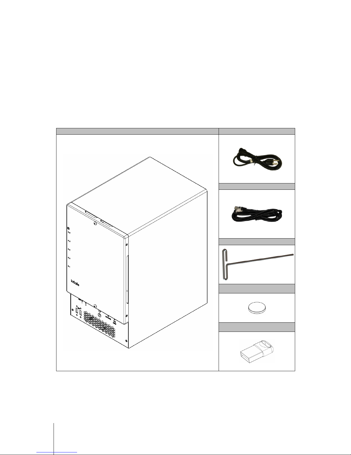
Before you start setting up the ioSafe, please check the package contents to verify that you have received the
items below. Please also read the safety instructions carefully before use to prevent your ioSafe from any
damages.
Package Contents
Main unit x1
AC power cord x1
RJ-45 LAN cable x1
3mm Hex Tool x1
Hex Tool Magnet x1
USB Recover Media x1
Page 4

4
ioSafe at a Glance
No.
Article Name
Location
Description
1)
HD Indicators Front Panel
The LED indicator is used to display the status of the internal disks. For more
information, see "Appendix B: LED Indication Table" on Page 17.
2)
USB 2.0 Ports Front Panel
The ioSafe offers USB ports for adding additional external hard drives, USB
printers, or other USB devices.
3)
LAN Indicators Front Panel
The LED indicator is used to display the status of the LAN Connections. For
more information, see "Appendix B: LED Indication Table" on Page 17.
4)
Power Button Front Panel
The power button is used to turn your ioSafe on or off.
To turn off your ioSafe, press the Power Button and hold it until you hear a beep
sound and the Power LED starts blinking.
5)
Locator Front Panel
The LED indicator is used to display the status of the internal disks and the
system. For more information, see "Appendix B: LED Indication Table" on Page
17.
6)
Fan Alert
Indicator
Front Panel
The Fan Alert indicator is used to display an error with the fans.
7)
Raid
Management
Port
Back Panel
Used to configure and communicate directly with the RAID Card.
8)
UID LED
“Locator”
Back Panel
When the UID button is pressed, the front Locator and rear UID LED indicator
flashes blue. Press the UID Reset button again to stop the indicator from
flashing.
UID Reset
“Locator”
9)
D-Sub Port Back Panel
VGA Port for connecting a monitor
Page 5
5
No.
Article Name
Location
Description
10)
LAN 1 Port Back Panel
The LAN ports are where you connect RJ-45 cable to the ioSafe.
11)
LAN 2 Port Back Panel
The LAN ports are where you connect RJ-45 cable to the ioSafe.
12)
Power Port Back Panel
The power port is where you connect the power cord to the ioSafe.
13)
IPMI LAN Port Back Panel
Intelligent Platform Management Interface (IPMI) is a set of computer
interface specifications that provides management and monitoring capabilities
independently of the host system's CPU, firmware (BIOS or UEFI)
and operating system.
14)
USB 3.0 Ports Back Panel
The ioSafe offers USB ports for adding additional external hard drives, USB
printers, or other USB devices.
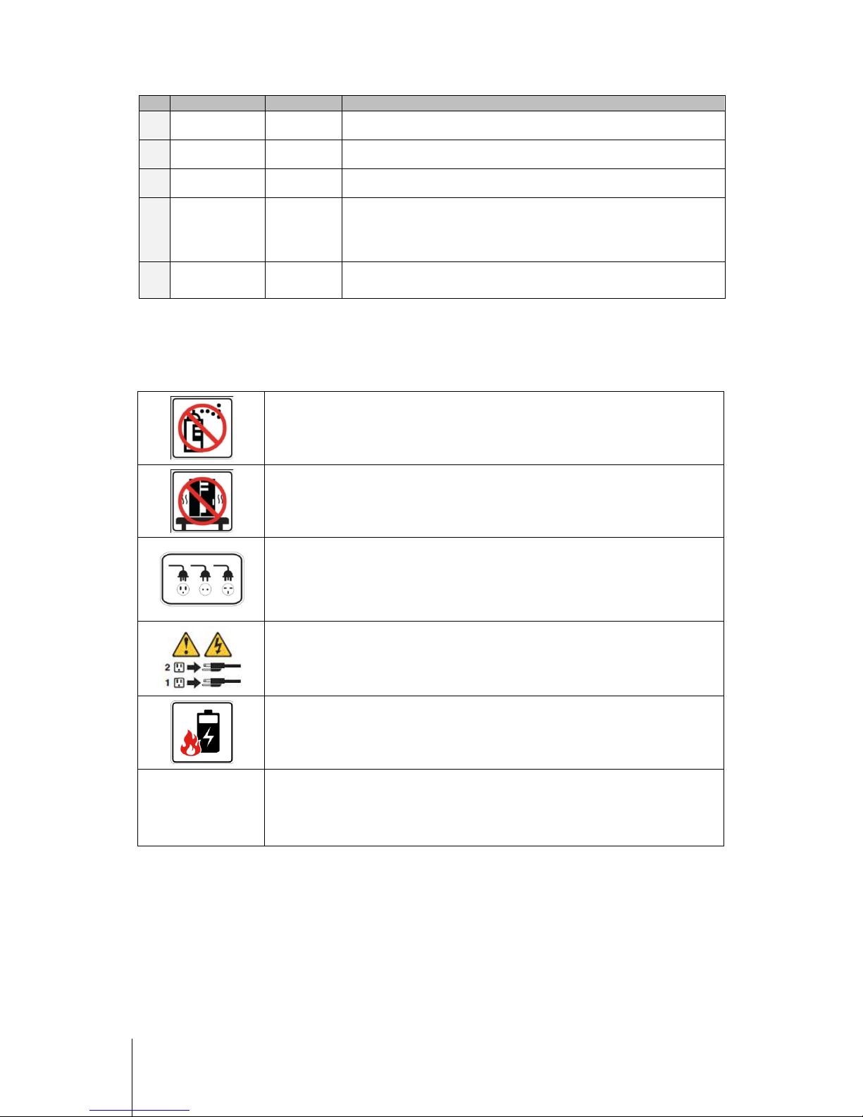
Safety Instructions
Before cleaning, unplug the power cord first. Wipe ioSafe product with damp paper towels.
Do not place the ioSafe
product on a cart, table, or desk, which is not stable to avoid the product
from falling over.
The power cord must plug in to the right supply voltage. Make sure that the supplied AC voltage
is correct and stable.
To remove all electrical current from the device, ensure that all power cords are disconnected
from the power source.
Risk of explosion if battery
is replaced with an incorrect type. Dispose of used batteries
appropriately.
3-2-1
At ioSafe, we suggest a minimum of the "3-2-
1 Rule" for backup: Make 3 complete copies of your
data, keep them on at least 2 separate systems, and have at least 1
protected from natural
disaster.
Page 6
6
Chapter 2: Hardware Setup
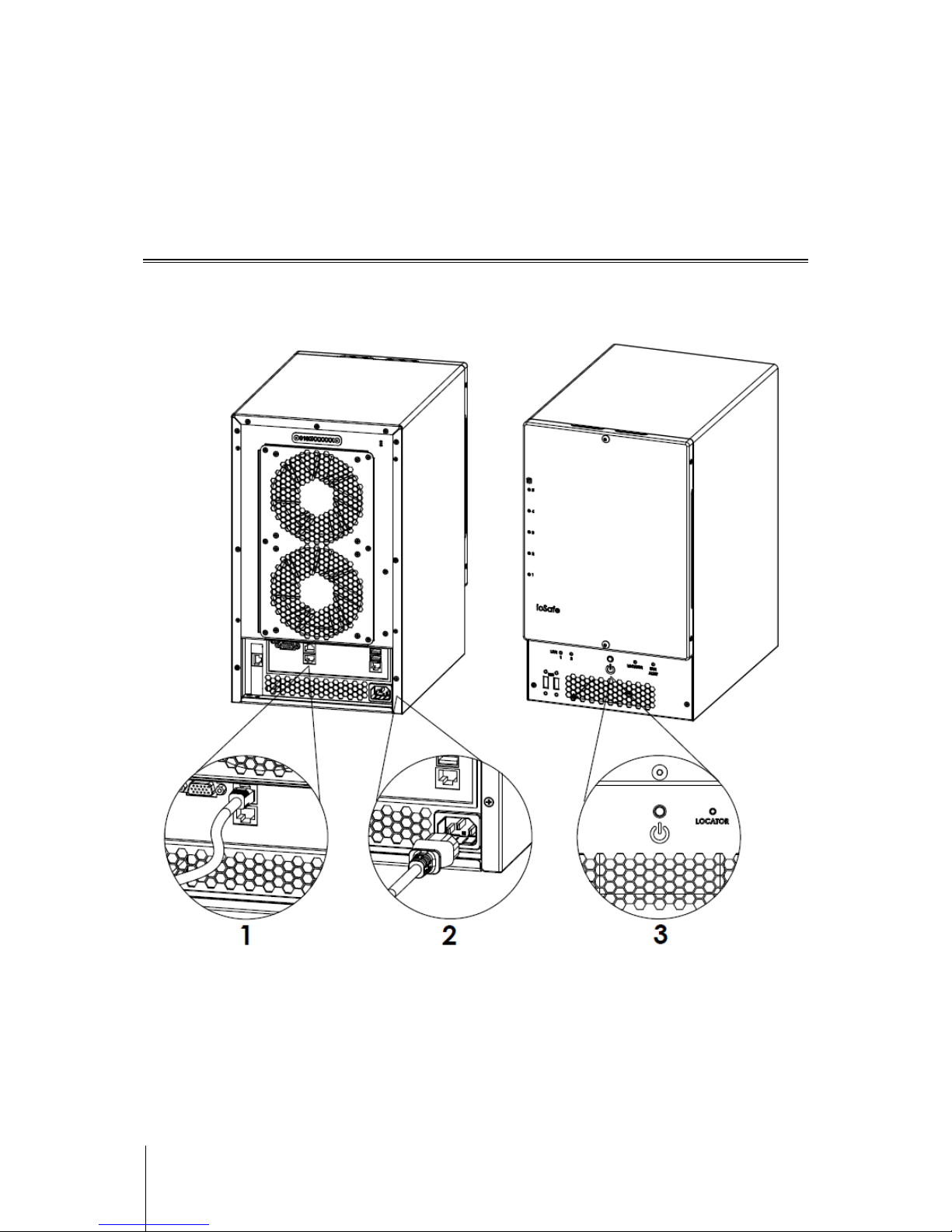
Connecting Your ioSafe
1 Use the LAN cable to connect the ioSafe to your switch/router/hub.
2 Connect one end of the power cord to the power port of your ioSafe, and the other to the power outlet.
3 Now your ioSafe is ready to power up.
Page 7

7
Chapter 3: Initial Start-up
Powering up the system
1 Press the Power On/Off button.
2 Confirm a successful power on sequence by ensuring that the Power On/Off LED is illuminated blue.
3 After the system starts, log into Windows Server 2012 R2 using the default credentials
"Administrator / password"
Page 8

8
Activating ShadowProtect
1 Once you have successfully logged into the BDR double click on the ShadowProtect SPX icon to open the
application
2 ShadowProtect SPX will prompt you to login with the server’s administrator login and password.
3 Once logged in, ShadowProtect will require an activation key. This should have been provided by ioSafe.
4 Select Activate License Now. Note: You will require and active internet connection to activate.
Page 9

9
5 You should be prompted to enter your License key and other information. Once entered select “I agree”
Note: This information is important should you ever need to restore the Server and/or need to request a
replacement license key.
Note: Do Not check Socket Licensing Service
Page 10

10
Chapter 4: Component replacement
Tools and Parts for Hard Disk Installation
A Phillips screwdriver
3mm Hex Tool (included)
At least one 3.5" or 2.5" SATA hard disk
(Please visit www.iosafe.com for compatible hard disk models.)
Warning: If you install a hard disk that contains data, the system will format the hard disk and erase all data. If you
need the data in the future, please back it up before installation.
Install or Replace Hard Disks
6 Remove the Front Cover using the include 3mm Hex Tool
Page 11

11
7 Remove the Waterproof Drive Cover using the 3mm Hex Tool.
8 Remove the Drive trays using the provided 3mm Hex Tool.
Page 12

12
9 Install a compatible Hard Drive into each Drive Tray using (4x) Drive Screws and a Phillips screwdriver.
(Please visit www.iosafe.com for compatible hard drives models.)
Note: If you want to set up a RAID set, it is recommended that all installed hard disks are of the same size to make
the best use of hard disk capacity.
10 Insert the loaded hard drive tray into the empty hard drive bay and tighten the screws using the 3mm
Hex Tool.
Important: Make sure the tray is pushed in all the way. Otherwise, the hard disk might not be able to function
properly.
Page 13

13
11 Replace the Waterproof Drive Cover and securely tighten using the supplied 3mm Hex Tool
WARNING: BE SURE TO TIGHTEN THIS SCREW USING THE PROVIDED HEX TOOL. THE HEX TOOL IS
DESIGNED TO FLEX SLIGHTLY WHEN THE SCREW IS SUFFICIENTLY TIGHT AND THE WATERPROOF
GASKET IS PROPERLY COMPRESSED. AVOID USING TOOLS OTHER THAN THE SUPPLIED HEX
TOOL AS YOU COULD UNDER TIGHTEN OR BREAK THE SCREW.
12 Install the Front Cover to finish the installation and protect the drives from fire. Keep the Hex Tool
nearby for future use. A magnet is provided to attach the Hex Tool to the back of the ioSafe or some other
convenient location.
Page 14

14
Replace System Fan Assembly
If your fans are not working properly on your ioSafe the Fan Fault LED will illuminate on the front panel. Follow
the steps below to replace the malfunctioning fans with a good set.
To replace the system fans:
1 Shut down your ioSafe. Disconnect all cables connected to your ioSafe to prevent any possible damages.
2 Remove the 6 perimeter screws that secure the malfunctioning fan assembly.
3 Remove the malfunctioning fan assembly:
a Pull the assembly from the back panel of your ioSafe to expose the fan connections.
b Disconnect the fan cables from the connector located near the bottom of the fan socket, and then remove
the assembly.
4 Install the new fan assembly:
a Connect the fan cables of the new fans to the fan connectors.
5 Replace and tighten the 6 screws you removed in step 2.
Page 15

15
Chapter 5: Product Support
Congratulations! You are now ready to manage and enjoy all the features of your ioSafe. For more information
regarding specific features, please refer to our online resources available at www.iosafe.com
Data Recovery Procedure
If the ioSafe faces possible data loss for any reason, you should immediately call the ioSafe Disaster Response
Team at 1-888-984-6723 (US & Canada) or 1-530-820-3090 (International) extension 430. You can also send an
email to disastersupport@iosafe.com. The professionals at ioSafe can determine the best actions to take to
protect your valuable information. In some cases a self-recovery can be performed and provide you with
immediate access to your information. In other cases, ioSafe may request that the product be returned to the
ioSafe factory for data recovery. In any case, contacting ioSafe is the first step.
The general steps for disaster recovery are:
1. Email disastersupport@iosafe.com with your serial number, product type and date of purchase.
2. If you cannot email, call ioSafe Disaster Support Team at 1-888-984-6723 (US & Canada) or 1-530-8203090 (International) extension 430
3. Report disaster event, and obtain return shipping address/instructions
4. Follow ioSafe team instructions on proper packaging.
5. ioSafe will recover all data which is recoverable according to the terms of the Data Recovery Service Terms
and Conditions.
6. ioSafe will then place any recovered data on a replacement ioSafe device
7. ioSafe will ship the replacement ioSafe device back to the original user
8. Once the primary server / computer is repaired or replaced, the original user should restore the primary drive
data with the ioSafe backup data
Contact Us
Customer Support
USA Toll Free Phone: 888.98.IOSAFE (984.6723) x400
International Phone: 530.820.3090 x400
Email: customersupport@iosafe.com
Technical Support
USA Toll Free Phone: 888.98.IOSAFE (984.6723) x450
International Phone: 530.820.3090 x450
Email: techsupport@iosafe.com
Disaster Support
US Toll Free Phone: 888.98.IOSAFE (984.6723) x430
International Phone: 530. 820.3090 x430
Email: disastersupport@iosafe.com
Corporate Headquarters
ioSafe, Inc.
12760 Earhart Avenue
Auburn CA 95602
Page 16

16
Appendix
Appendix C: Specifications
Item
ioSafe SERVER 5
Fire Protection Protects data from fire. Up to 1550°F (843°C), 30 minutes per ASTM E-119.
Flood Protection Protects data from flood. Fully submersed, fresh or salt water, 10 foot (3m) depth, 72
CPU Model Intel Xeon D-1521
CPU Frequency 2.4GHz 4-Core, 8 Threads
System Memory Up to 128GB DDR4 ECC RDIMM
Memory Expandable yes
Drive Bays 5
Compatible Drive Type 3.5" or 2.5" SATA (III)
RAID Controller Areca ARC-1226-8i
Hot Swappable Drives Yes
Ethernet 2X 10GBASE-T LAN 1000/100
Rear Panel I/O
VGA Port – D-sub x1
USB 3.0 x 2
RJ45 10Gbase-T ports x2
Front Panel I/O USB 2.0 x 2
Size (HxWxD) 14.8” x 8.7” x 12.5” (375mm x 221mm x 317mm)
Weight 58.5lbs (26.5Kg) (without hard drives & external cabling)
Graphics Controller ASPEED AST2400
Max. Resolution 1920x1200@60Hz
System Fans 120mm x2
Noise Level 61dB
Power Supply Unit 220W
AC Input Power Voltage 100V to 240V AC
Power Frequency 50/60Hz
Power Consumption 141W
Operating Temperature 40 to 95˚F (5 to 35˚C)
Storage Temperature -5 to 140˚F (-20 to 60˚C)
Relative Humidity 5% to 95% RH
Page 17

17
Appendix
Appendix B: LED Indication Table
LED Indication Color Status Description
Power Blue
Static Powered on
Off Powered off
Hard Drive Status
Indicator
Green
(activity)
Blinking Disk is being accessed
Off Disk is idle
Yellow
(fault)
Blinking
When the fault LED is blinking
(2 times/sec), that disk drive has failed and
should be hot swapped immediately.
When the activity LED is lit and
fault LED is fast blinking (10
times/sec) there is rebuilding activity on that
disk drive.
Through the Raid Management Portal, a user
can also identify specific drive which fast
blinks a single fault LED or to locate a system
by fast blinking all the drive fault LED’s
Static No disk present
Off Disk is Present and status is normal
Front LAN 1, Lan 2 Green
Static Connection Established
Blinking Network is active
Off Network is down
Fan Alert Orange
Off Fans Normal
Static HDD above 61C or Fan is Stopped
Locator Blue Static Helps locate the Device being managed
Rear LAN (ACT/Link) Green
Off No Link
Blinking Data Activity
On 100Mbps Connection
Rear LAN (SPEED) Green
Off 10Mbps Connection
Off 100Mbps Connection
On 1Gbps Connection
 Loading...