

Page 1
Powered by Synology DSM
910-11835-00 Rev02 HARDWARE GUIDE, 1517, ENG
ioSafe 1517 Hardware Guide
Page 2

Table of Contents
Chapter 1: Before You Start
Package Contents ............................................................................................................................................... 3
ioSafe at a Glance ............................................................................................................................................... 4
Safety Instructions ............................................................................................................................................... 5
Chapter 2: Hardware Setup
Tools and Parts for Hard Disk Installation ........................................................................................................... 6
Install Hard Disks ................................................................................................................................................ 6
Connecting Your ioSafe .................................................................................................................................... 10
Replace System Fan Assembly ........................................................................................................................ 11
Chapter 3: Install Synology DiskStation Manager
Install DSM with Web Assistant ......................................................................................................................... 12
Chapter 4: Product Support
Data Recovery Procedure ................................................................................................................................. 13
Contact Us ........................................................................................................................................................ 13
Appendix A: Specifications
Appendix B: LED Indication Table
2
Page 3
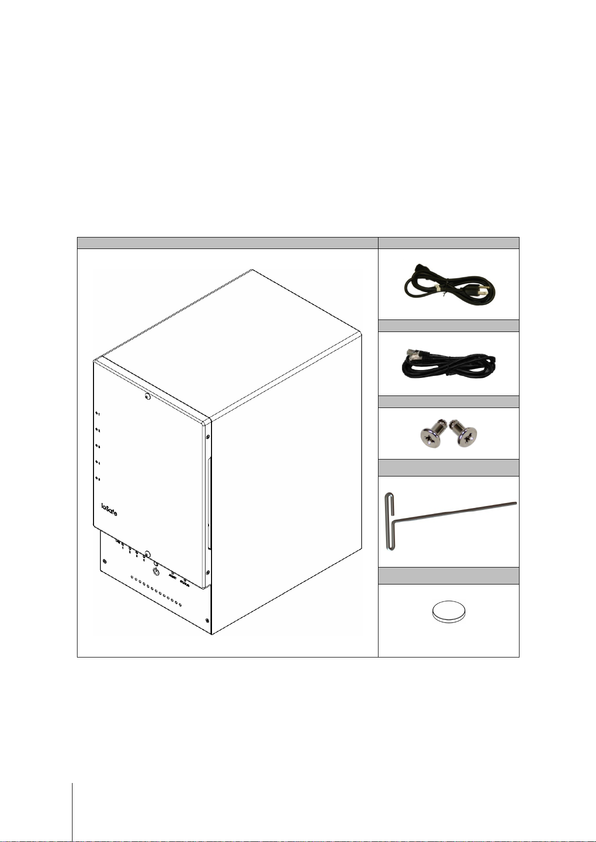
Main unit x 1
AC power cord x 1
RJ-45 LAN cable x 1
Screws for 3.5” hard drives x 24
Chapter 1: Before You Start
Before you start setting up the ioSafe, please check the package contents to verify that you have received the
items below. Please also read the safety instructions carefully before use to prevent your ioSafe from any
damages.
Package Contents
3mm Hex Tool x1
Magnet x1
3
Note: For storing the Hex Tool
on the back of the device
Page 4
No.
Article Name
Location
Description
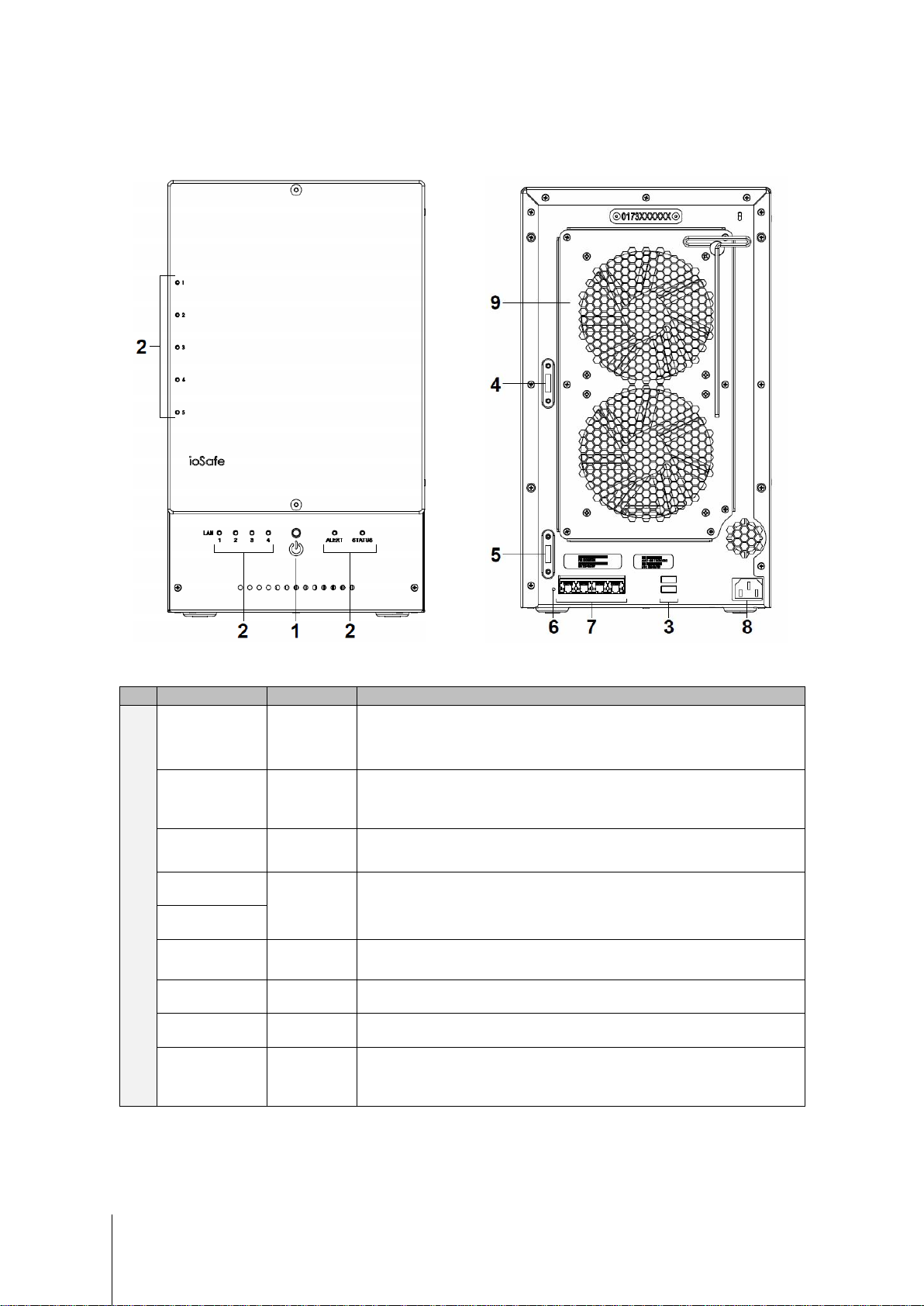
ioSafe at a Glance
1)
Power Button Front Panel
2)
LED Indicators Front Panel
3)
USB 3.0 Ports Back Panel
4)
5)
6)
7)
8)
9)
eSATA 1
eSATA 2
RESET Button Back Panel
LAN Ports Back Panel
Power Port Back Panel
Fans Back Panel
Safety Instructions
Back Panel
The power button is used to turn your ioSafe on or off.
To turn off your ioSafe, press the Power Button and hold it until you hear a beep
sound and the Power LED starts blinking.
The LED indicator is used to display the status of the internal disk and t he
system. For more information, see "Appendix A: LED Indication Table" on Page
15.
The ioSafe offers USB ports for adding additional external hard drives, USB
printers, or other USB devices.
The eSATA ports are used to connect external SATA disks or Expans ion Units
to the ioSafe.
1. To restore IP, DNS, passwords for the admin account to default value.
2. To reinstall the ioSafe.
The LAN ports are where you connect RJ-45 cable to the ioSafe.
The power port is where you connect the power cord to the ioSafe.
The fans are built to exhaust waste heat. It will start automatically when the
server starts. If the fan is malfunctioning, the system will beep every few
seconds.
1
-----
1
For more information about ioSafe Expansion Unit supported by your DiskStation, please visit www.iosafe.com .
4
Page 5
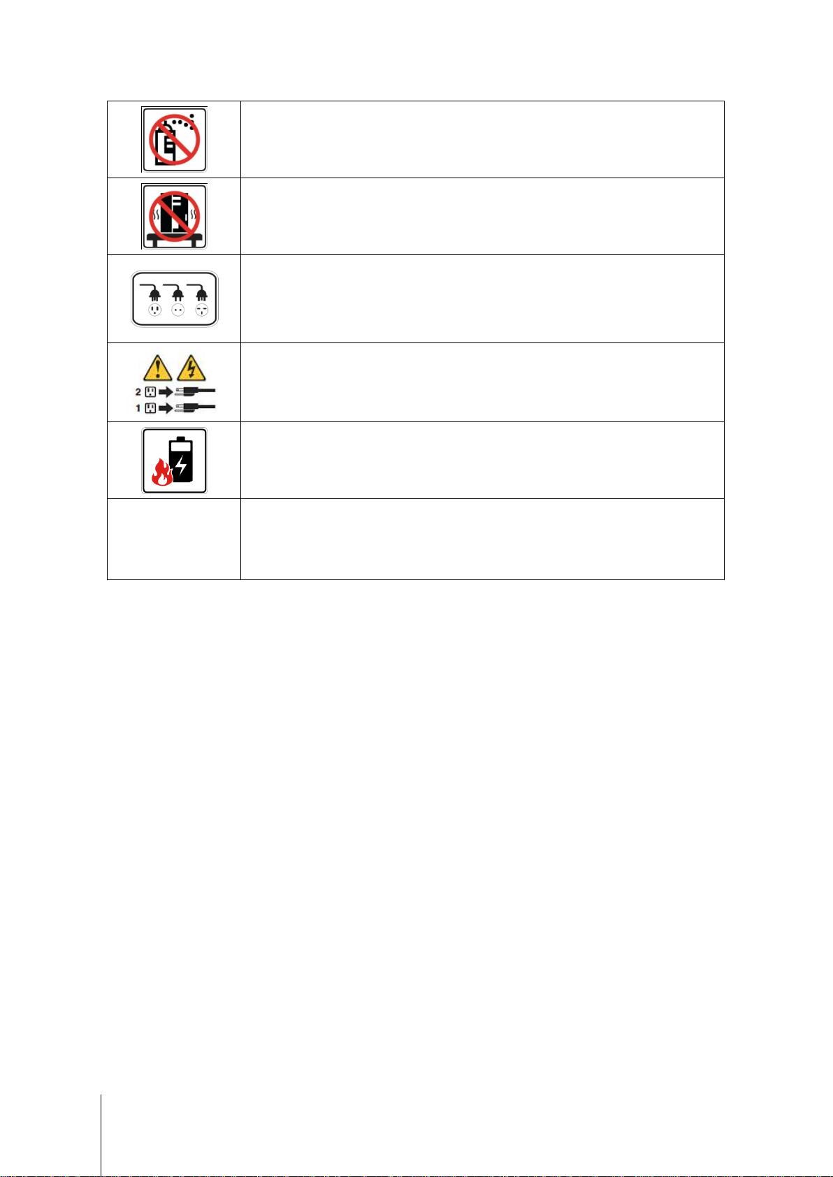
product on a cart, table, or desk, which is not stable to avoid the product
To remove all electrical current from the device, ensure that all power cords are disconnected
is replaced with an incorrect type. Dispose of used batteries
1 Rule" for backup: Make 3 complete copies of your
protected from natural
Before cleaning, unplug the power cord first. Wipe ioSafe product with damp paper towels.
Do not place the ioSafe
from falling over.
The power cord must plug in to the right supply voltage. Make sure that the supplied A C voltage
is correct and stable.
from the power source.
3-2-1
Risk of explosion if battery
appropriately.
At ioSafe, we suggest a minimum of the "3-2data, keep them on at least 2 separate systems, and have at least 1
disaster.
5
Page 6
Chapter 2: Hardware Setup
Tools and Parts for Hard Disk Installation
A Phillips screwdriver
3mm Hex Tool (included)
At least one 3.5" or 2.5" SATA hard disk
(Please visit www.iosafe.com for compatib le hard dis k mod els.)
Warning: If you ins tall a hard disk that contains data, the system will format the hard disk and eras e all data. If you
need the data in the fut ure, please back it up before install ation.
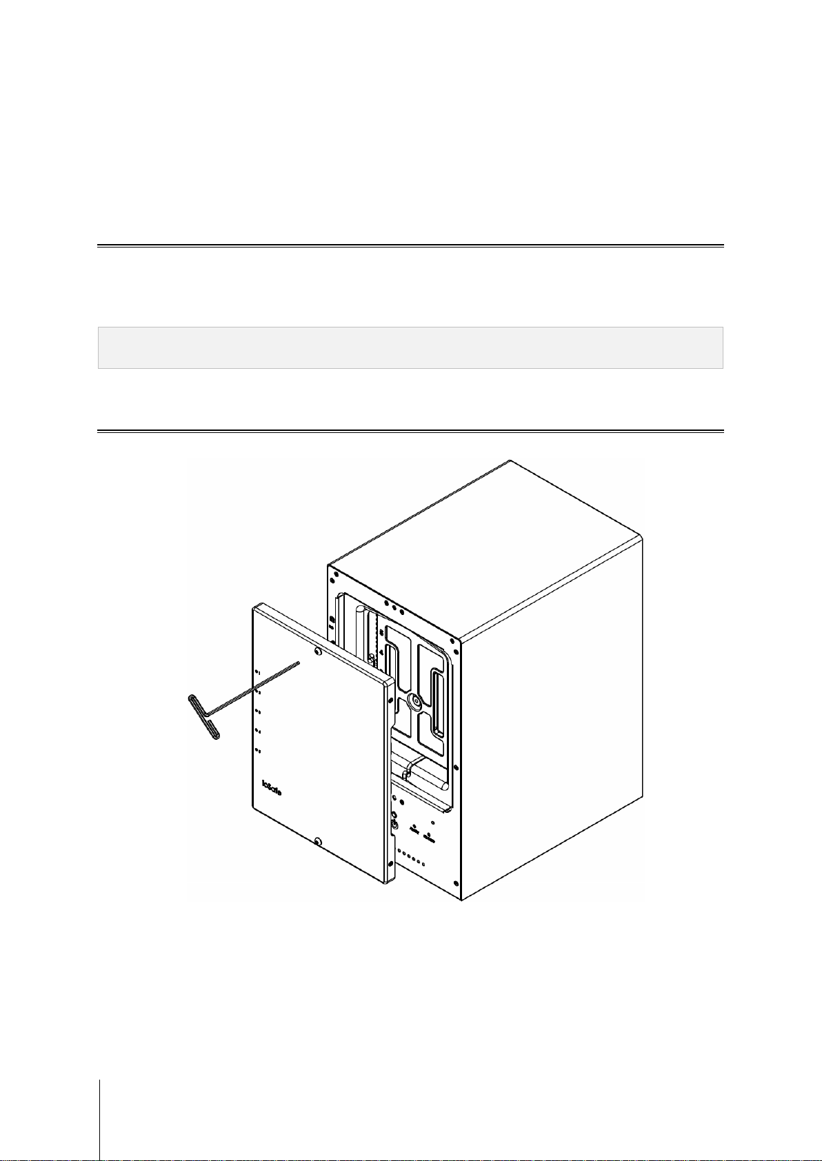
Install Hard Disks
1 Remove the Front Cover using the include 3mm Hex Tool
6
Page 7

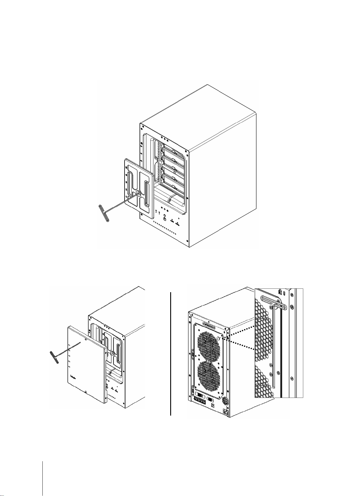
2 Remove the Waterproof Drive Cover using the 3mm Hex Tool.
3 Remove the Drive trays using the provided 3mm Hex Tool.
7
Page 8

4 Install a compatible Hard Drive into each Drive Tray using (4x) Drive Screws and a Phillips screwdriver.
(Please visit www.iosafe.com for compatib le hard driv es mo dels .)
Note: If you want t o set up a RAID set, it is recommended that all installed hard disks are of the same size to make
the best use of hard disk capacity.
5 Insert the loaded hard drive tray into the empty hard drive bay and tighten the screws using the 3mm Hex Tool.
Important: Make sure the tray is pushed in all the way. Otherwise, the hard disk might not be able to function
properly.
8
Page 9
6 Replace the Waterproof Drive Cover and securely tighten using the supplied 3mm Hex Tool
WARNING: BE SURE TO TIGHTEN THIS SCREW USING THE PROVIDED HEX TOOL. THE HEX TOOL IS
DESIGNED TO FLEX SLIGHTLY WHEN THE SCREW IS SUFFICIENTLY TIGHT AND THE WATERPROOF
GASKET IS PROPERLY COMPRESSED. AVOID USING TOOLS OTHER THAN THE SUPPLIED HEX
TOOL AS YOU COULD UNDER TIGHTEN OR BREAK THE SCREW.
7 Install the Front Cover to finish the installation and protect the drives from fire. Keep the Hex Tool nearby for
future use. A magnet is provided to attach the Hex Tool to the back of the ioSafe or some other convenient
location.
9
Page 10

Connecting Your ioSafe
1 Use the LAN cable to connect the ioSafe to your switch/router/hub.
2 Connect one end of the power cord to the power port of your ioSafe, and the other to the power outlet.
3 Press and hold the power button to turn on your ioSafe.
Your ioSafe is now online and detectable from a network computer.
10
Page 11

Replace System Fan Assembly
Your ioSafe will play beep sounds if either of the system fans is not working. Follow the steps below to replace
the malfunctioning fans with a good set.
To replace the system fans:
1 Shut down your ioSafe. Disconnect all cables connected to your ioSafe to prevent any possible damages.
2 Remove the 7 perimeter screws that secure the malfunctioning fan assembly.
3 Remove the malfunctioning fan assembly:
a Pull the assembly from the back panel of your ioSafe to expose the fan connections.
b Disconnect the fan cables from the connector located near the bottom of the fan socket, and then remove
the assembly.
4 Install the new fan assembly:
a Connect the fan cables of the new fans to the fan connectors.
5 Replace and tighten the 7 screws you removed in step 2.
11
Page 12

Chapter 3: Install Synology DiskStation Manager
Synology DiskStation Manager (DSM) is a browser-based operating system which provides tools to access and
manage your ioSafe. When installation is complete, you will be able to log into DSM and start enjoying all the
features of your ioSafe powered by Synology. To get started, please see the steps below.
Install DSM with Web Assistant
Your ioSafe comes equipped with Web Assistant, a browser-based installation tool which helps you download,
configure, and install the newest version of DiskStation Manager (DSM). Before installing DSM with Web
Assistant, please check the follow ing:
Your computer and your ioSafe must be connected to the same local network.
In order to download the latest version of DSM, Internet access must be available during installation.
After confirming, please follow the steps below:
1 Power on your ioSafe.
1 Open a web browser on your computer and go to find.synology.com.
Note: Web Assis tant is optimized for Chrome and Firefox web browsers.
2 Web Assistant will find your ioSafe within the local network. The status of your ioSafe should be Not Installed.
3 Click Connect to begin the setup process. Follow the onscreen instructions to complete the setup process.
Note: ioSafe uses an unmodified vers ion of Synology’s DSM. The software int erface will sometimes refer to the
Synology Product the ioSafe is based on; Synology DS1517
4 A web browser should open showing the Login screen. Enter the ‘admin’ as the username and leave the
password field blank as shown below.
Default user name: admin
admin
Leave this field empty
12
Page 13

Chapter 4: Product Support
Congratulations! You are now ready to manage and enjoy all the features of your ioSafe. For more information
regarding specific features, please check out DSM Help or refer to our online resources available at
www.iosafe.com or www.synology.com.
Data Recovery Procedure
If the ioSafe faces possible data loss for any reason, you should immediately call the ioSafe Disaster Response
Team at 1-888-984-6723 (US & Canada) or 1-530-820-3090 (Intern ational) extension 430. You can also send an
email to disastersupport@iosafe.com. The professionals at ioSafe can determine the best actions to take to
protect your valuable information. In some cases a self-recovery can be performed and provide you with
immediate access to your information. In other cases, ioSafe may request that the product be returned to the
ioSafe factory for data recovery. In any case, contacting ioSafe is the first step.
The general steps for disaster recovery are:
1. Email disastersupport@iosafe.com with your serial number, product type and date of purchase.
2. If you cannot email, call ioSafe Disaster Support Team at 1-888-984-6723 (US & Canada) or 1-530-8203090 (International) extension 430
3. Report disaster event, and obtain return shipping address/instructions
4. Follow ioSafe team instructions on proper packaging.
5. ioSafe will recover all data which is recoverable according to the terms of the Data Recovery Service Terms
and Conditions.
6. ioSafe will then place any recovered data on a replacement ioSafe device
7. ioSafe will ship the replacement ioSafe device back to the original user
8. Once the primary server / computer is repaired or replaced, the original user should restore the primary drive
data with the ioSafe backup data
Contact Us
Customer Support
USA Toll Free Phone: 888.98.IOSAFE (984.6723) x400
International Phone: 530.820.3090 x400
Email: customersupport@iosafe.com
Technical Support
USA Toll Free Phone: 888.98.IOSAFE (984.6723) x450
International Phone: 530.820.3090 x450
Email: techsupport@iosafe.com
Disaster Support
US Toll Free Phone: 888.98.IOSAFE (984.6723) x430
International Phone: 530. 820.3090 x430
Email: disastersupport@iosafe.com
Corporate Headquarters
ioSafe, Inc.
10600 Industrial Ave, Suite 120
Roseville CA 95678
13
Page 14

Item
ioSafe NAS 1517
Fire Protection
Protects data from fire. Up to 1550°F (843°C), 30 minutes per ASTM E-119.
Flood Protection
Protects data from flood . Full y subm e rs ed, f re sh or salt wat er, 10 foot (3m) depth, 72 hours.
Internal HDD
3.5" or 2.5" SATA (II) x 5
Hot Swappable HDD
Yes
LAN Port
Gigabit x 4
USBCopy
No
Size (H xWxD) (mm)
375 x 222 x 318
Weight (Kg)
27 (59 lbs)
HDD Hibernation
Yes
Scheduled Power On/Off
Yes
Wake on LAN
Yes
‧Português Europeu‧Türkçe ‧Český ‧日本語‧한국어‧繁體中文‧简体中文
Appendix A: Specifications
Appendix
Max. Capacity
External Device Ports
Supported Clients
File System
Volume Type
60TB (5x 12TB hard drives)
180TB (15x 12TB hard drives) with two DX517 (expansion uni t s)
USB 3.0 x 2
eSATA x 2
Windows XP onward
Mac OS X 10.5 onward
Ubuntu 9.04 onward
‧Internal: EXT4
‧External disk only: EXT4, EXT3, FAT, NTFS, HFS+, exFAT
‧Basic ‧JBOD ‧RAID 0 ‧RAID 1
‧RAID 5 ‧RAID 6‧RAID 10
‧Synology Hybrid RAID (Up to 2-Disk Fault Tolerance)
14
Language Localization
Power Consumption And
Environment Requirements
‧English ‧Deutsch ‧Français ‧Italiano ‧Español ‧Dansk ‧Norsk ‧Svensk
‧Nederlands ‧Русский ‧Polski ‧Magyar ‧Português do Brasil
Line voltage: 100V to 240V AC
Frequency: 50/60Hz
Operating Temperature: 40 to 95˚F (5 to 35˚C)
Storage Temperature: 15 to 140˚F (-10 to 60˚C)
Relative Humidity: 5% to 95% RH
Maximum Operating Altitude: 6500 feet (2000m )
Page 15

Appendix B: LED Indication Table
LED Indication Color Status Description
Green
STATUS
Orange
Appendix
Static Volume Normal
Off HDD Hibernation
Available volume space < 1GB
Static
Available volume space < 1 %
Volume degraded or crashed
Blinking
DSM not installed
Front LAN Green
Rear LAN (on upper
side of jack)
Rear LAN (on lower side
of jack)
Hard Drive Status
Indicator
(on tray)
ALERT Orange
Green/orange Alternating No internal disk
Static Gigabit connection
Blinking Network is active
Off Network is down
Green Static Gigabit connection
Static 100 Mb connection
Orange
Off 10 Mb connection
Static Network is connected
Green
Green
Orange Static Cannot Read/Write
Blinking Network is active
Off Network is down
Static Disk ready
Blinking Disk is being accessed
Off No internal disk
Blinking FAN failure or over t emperature
Off System normal
15
Static Power ready
Booting up
Power Blue
Blinking
Shutting down
Off Power off
 Loading...