

查询ATO2812T供应商
PD - 94582
A T O28XXT SERIES
ADVANCED ANALOG
28V Input, T riple Output
HYBRID-HIGH RELIABILITY
DC/DC CONVERTERS
Description
The ATO28XXT Series of DC/DC converters feature
high power density and an extended temperature range
for use in military and industrial applications. Designed
to the nominal input requirements of MIL-STD-704D,
these devices have nominal 28VDC inputs with +5V
and ±12V or +5V and ±15V triple outputs to satisfy a
wide range of requirements. The circuit design incorporates a pulse width modulated push-pull topology
operating in the feed-forward mode at a nominal switching frequency of 250KHz. Input to output isolation is
achieved through the use of transformers in the forward and feedback circuits.
The advanced feedback design provides fast loop response for superior line and load transient characteristics and offers greater reliability and radiation tolerance than devices incorporating optical feedback circuits.
Three standard temperature grades are offered. Refer
to Part Number section. They are provided in a standard plug-in package for PC mounting or in a flanged
package for more severe environments.
These converters are manufactured in a facility fully
qualified to MIL-STD-1772. All processes used to manufacture these converters have been qualified to enable
Advanced Analog to deliver compliant devices. Two
screening grades are available to satisfy a wide range
of requirements. The CH grade converters are fully
compliant to MIL-PRF-38534 for class H. The HB grade
converters are processed to full class H screening requirements but do not have class H element evaluation as directed by MIL-PRF-39534. Both grades are
fully tested and operate over the full military temperature range without derating of output power. Variations
in electrical, mechanical and screening can be accommodated. Extensive computer simulation using complex modeling enables modest design modifications to
be accommodated. Contact Advanced Analog with
specific requirements.
Features
n 16 to 40 VDC Input Range (28VDC Nominal)
n 5V, ±12V or 5V, ±15V Outputs Available
n Indefinite Short Circuit and Overload
Protection
n 15 Watts Output Power
n Fast Loop Response for Superior Transient
Characteristics
n Operating Temperature Range from -55°C to
+125°C Available
n Popular Industry Standard Pin-out
n Resistance Seam Welded Case for Superior
Long Term Hermeticity
n Efficiencies up to 81%
n Shutdown from External Signal
n 200,000 Hour MTBF at 85°C
www.irf.com 1
ATO
11/20/02
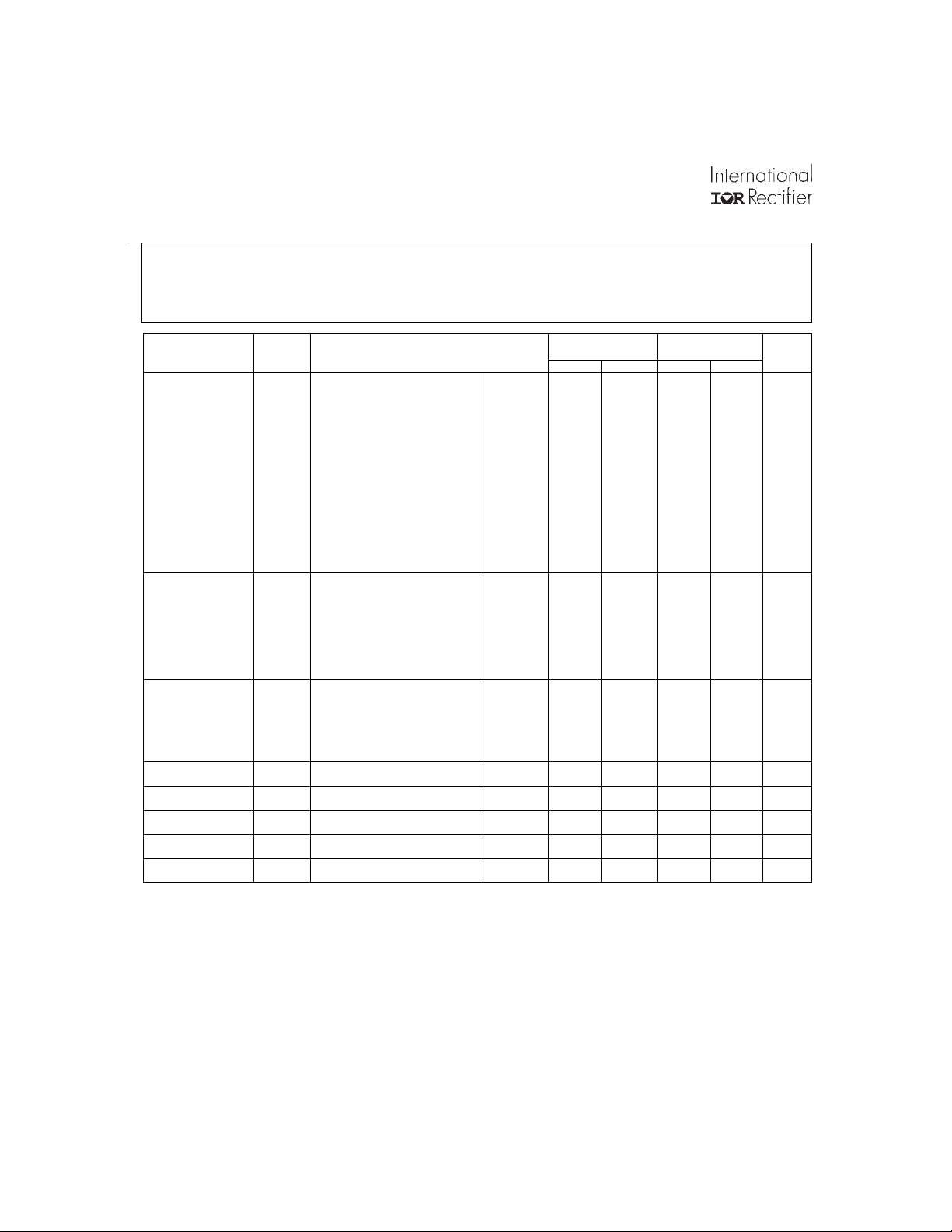
ATO28XXT Series
Specifications
T
= -55°C to +85°C, V
CASE
ABSOLUTE MAXIMUM RATINGS
Input Voltage -0.5V to 50V
Power Output Intern ally lim ite d , 1 7 .5 W typical
Soldering 30 0°C for 10 seconds
Temperature Range
6
Opera ting - 5 5°C to +115°C case
Storage -65°C to +135°C
TEST
STATIC
CHARACTERISTICS
OUTPUT
Voltage 1 V
1,2,3
Current
Ripple Voltage
Power
REGULATION
Line
Load
INPUT
Current
Ripple Current
I
1,4
1,2,3
P
1,3
1,3
EFFICIENCY EFF I
ISOLATION ISO Input to output or any pin to
Load Fault
Power Dissipation
Switching Frequency FS I
Inhibit Open Circuit
Voltage
Notes to Specifications
1. Tested at each output.
2. Parameter guaranteed by line and load regulation tests.
3. At least 20 percent of the total output power should be taken from the (+5V volt) main output.
4. Bandwidth guaranteed by design. Tested for 20KHz to 2MHz.
5. An overload is that condition with a load in excess of the rated load but less than that necessary to trigger the short circuit
protection and is the condition of maximum power dissipation.
6. Above 85°C case temperature, derate output power linearly to 0 at 115°C case.
SYMBOL
V
4
3
= +28V ± 5% unless otherwise specified
IN
-55°C ≤ T
I
OUT
OUT
RIP
OUT
VR
LINE
VR
LOAD
I
IN
I
RIP
P
D
VOI 9 13 9 13 V
= 0 (main)
OUT
I
= 0 (dual)1
OUT
VIN = 16, 28, and 40 V D C (main) 0.0 2000 0.0 2000 mA
VIN = 16, 28, and 40 VDC (dual)
VIN = 16, 28, and 40 VDC (dual)
BW = DC to 2 MHz (main)
V
= 16, 28, and 40 VDC
IN
BW = DC to 2 MHz (dual))
VIN = 16, 28, and 40 VDC (main)
(+dual)
(-dual)
(total)
V
= 16, 28, and 40 VDC
IN
= 0, 1000, 2000mA (main)
I
OUT
V
= 16, 28, and 40 VDC (dual)
IN
I
= 0, ±84, ±167mA (dual)
OUT
V
= 16, 28, and 40 VDC
IN
= 0, 1000, 2000mA (main)
I
OUT
V
= 16, 28, and 40 VDC
IN
= 0, ±84, ±167mA (dual)
I
OUT
I
= 0, Inhibit (pin 8)
OUT
Tied to input return (pin 10)
I
= 0, inhibit (pin 2) = open
OUT
I
= 2000 mA (main)
OUT
= ±167mA (dual)
I
OUT
BW = DC to 2MHz
= 2000mA (main)
OUT
= ±167mA (dual)
I
OUT
case (except pin 7) at 500 VDC,
Overload
Short Circuit
= 2000mA (main)
OUT
I
= ±167mA (dual)
OUT
Condition
≤ +85°C, VIN = 28 VDC ±5%, CL=0
C
unless otherwise specified Min Max Min Max Units
TC = 25°C
Over Temp
TC = 25°C
Over Temp
1
0.0
10
TC = 25°C
Over Temp
TC = 25°C
TC = 25°C
TC = 25°C
225 275 225 275 KHz
ATO2812T
4.95
4.90
11.88
±
11.76
±
2.5
2.5
15
5.05
5.10
12.12
±
12.24
±
208
±
80
40
10
25
30
±
60
±
50
60
±
15
40
50
76 76 %
100 100
8 6 8 6 W
ATO2815T
4.95
4.90
14.85
±
14.70
±
0.0
2.5
2.5
15
5.05
5.10
15.15
±
15.30
±
167
±
80
40 mVp-p
W
25
35
±
75
±
50
75
±
15
40
50
V
V
V
V
mA
mVp-p
W
W
W
mV
mV
mV
mV
mV
mA
mA
mAp-p
MΩ
W
2 www.irf.com
ATO28XXT Series
Specifications
T
= -55°C to +105°C, V
CASE
= +28V ± 5% unless otherwise specified
IN
ABSOLUTE MAXIMUM RATINGS
Input Vo ltag e -0.5V to 5 0 V
Power Output Intern a lly limited , 1 7 .5W typical
Soldering 300°C for 10 seconds
Temperature Range
6
Operating -5 5°C to +12 5°C case
Storage -65°C to +13 5°C
TEST
SYMBOL
-55°C ≤ T
≤ +105°C, VIN = 28 VDC ±5%, CL=0
C
unless otherwise specified
Condition
ATO2812T/ES
ATO2815T/ES
Min Max Min Max Units
STATIC
CHARACTERISTICS
OUTPUT
Voltage 1 V
1,2,3
Current
Ripple Voltage
I
BW = DC to 2 MHz (main)
1,2,3
Power
P
REGULATION
1,3
Line
1,3
Load
INPUT
Current
Ripple Current
EFFICIENCY EFF I
ISOLATION ISO Input to output or any pin to
Load Fault
Power Dissipation
Switching Frequency
Inhibit Open Circuit
Voltage
Notes to Specifications
I
OUT
OUT
VR
VR
V
RIP
OUT
LINE
LOAD
IIN
I
RIP
1,4
4
= 0 (main)
OUT
I
= 0 (dual)1
OUT
VIN = 16, 28, and 40 VDC (main) 0.0 2000 0.0 2000 mA
= 16, 28, and 40 VDC (dual)
V
IN
VIN = 16, 28, and 40 VDC
= 16, 28, and 40 VDC
V
IN
BW = DC to 2 MHz (dual))
VIN = 16, 28, and 40 VDC (main)
(+dual)
(-dual)
(total)
= 16, 28, and 40 VDC
V
IN
= 0, 1000, 2000mA (main)
I
OUT
V
= 16, 28, and 40 VDC (dual)
IN
= 0, ±84, ±167mA (dual)
I
OUT
= 16, 28, and 40 VDC
V
IN
I
= 0, 1000, 2000mA (main)
OUT
= 16, 28, and 40 VDC
V
IN
I
= 0, ±84, ±167mA (dual)
OUT
I
= 0, Inhibit (pin 8)
OUT
Tied to input return (pin 10)
= 0, inhibit (pin 2) = open
I
OUT
= 2000 mA (main)
I
OUT
I
= ±167mA (dual)
OUT
BW = DC to 2MHz
= 2000mA (main)
OUT
I
= ±167mA (dual)
OUT
TC = ±25°C
case (except pin 7) at 500 VDC,
TC = +25°C
3
PD
Overload, TC = +25°C
5
1
TC = 25°C
Over Temp
TC = 25°C
Over Temp
0.0
10
TC = 25°C
Over Temp
TC = 25°C
TC = 25°C
TC = 25°C
Short Circuit, TC = +25°C
I
F
S
VOI 9 13 9 13 V
= 2000mA (main)
OUT
I
= ±167mA (dual)
OUT
4.95
4.90
11.88
±
11.76
±
2.5
2.5
15
5.05
5.10
12.12
±
±
±
±
12.24
±
208
80
40
10
25
30
±
60
±
50
60
±
15
40
50
4.95
4.90
14.85
14.70
0.0
2.5
2.5
15
76 76 %
100 100
225
8
6
275
225
5.05
5.10
15.15
±
15.30
±
167
±
80
V
V
V
V
mA
mVp-p
40 mVp-p
W
25
35
±
75
±
50
75
±
15
40
50
W
W
W
mV
mV
mV
mV
mV
mA
mA
mAp-p
MΩ
8
6
275
W
W
KHz
1. Tested at each output.
2. Parameter guaranteed by line and load regulation tests.
3. At least 20 percent of the total output power should be taken from the (+5V volt) main output.
4. Bandwidth guaranteed by design. Tested for 20KHz to 2MHz.
5. An overload is that condition with a load in excess of the rated load but less than that necessary to trigger the short circuit
protection and is the condition of maximum power dissipation.
6. Above 105°C case temperature, derate output power linearly to 0 at 125°C case
www.irf.com 3

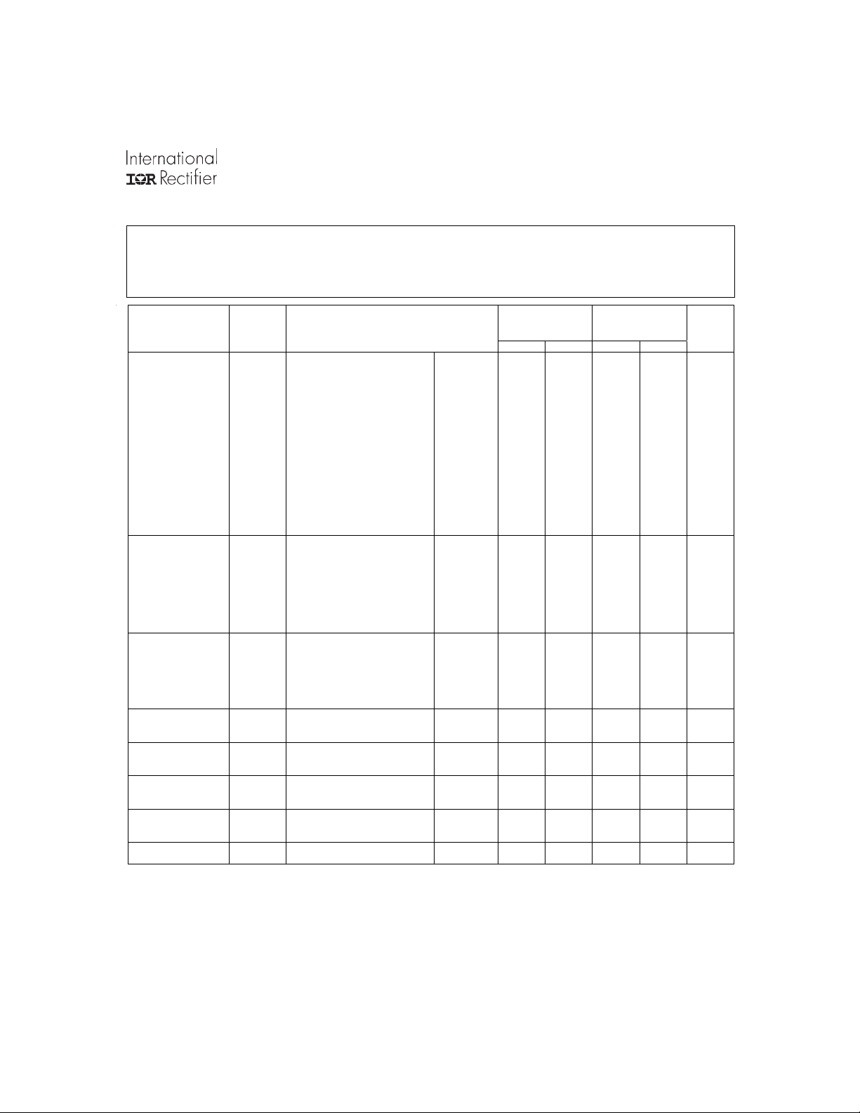
ATO28XXT Series
Specifications
T
= -55°C to +125°C, V
CASE
ABSOLUTE MAXIMUM RATINGS
Input Voltage -0.5V to 50V
Power O u tput Interna lly lim ite d , 1 7 .5 W ty p ic al
Soldering 30 0°C for 10 seconds
Temperature Range
6
Operating -5 5°C to +13 5°C case
Storage -65°C to +13 5°C
TEST
SYMBOL
Min Max Min Max Units
STATIC
CHARACTERISTICS
OUTPUT
Voltage 1 V
1,2,3
Current
Ripple Voltage
I
1,4
V
BW = DC to 2 MHz (main)
1,2,3
Power
P
REGULATION
1,3
Line
1,3
Load
INPUT
Current
Ripple Current
4
VR
VR
I
EFFICIENCY EFF I
ISOLATION ISO Input to output or any pin to
Load Fault
Power Dissipation
3
PD
Switching Frequency
Inhibit Open Circuit
Voltage
Notes to Specifications
VOI 9 13 9 13 V
1. Tested at each output.
2. Parameter guaranteed by line and load regulation tests.
3. At least 20 percent of the total output power should be taken from the (+5V volt) main output.
4. Bandwidth guaranteed by design. Tested for 20KHz to 2MHz.
5. An overload is that condition with a load in excess of the rated load but less than that necessary to trigger the short circuit
protection and is the condition of maximum power dissipation.
6. Above 125°C case temperature, derate output power linearly to 0 at 135°C case
= +28V ± 5% unless otherwise specified
IN
-55°C ≤ T
I
OUT
OUT
RIP
OUT
LINE
LOAD
I
IN
RIP
= 0 (main)
OUT
= 0 (dual)1
I
OUT
VIN = 16, 28, and 40 VDC (main) 0.0 2000 0.0 2000 mA
V
= 16, 28, and 40 VDC (dual)
IN
VIN = 16, 28, and 40 VDC
= 16, 28, and 40 VDC
V
IN
BW = DC to 2 MHz (dual))
VIN = 16, 28, and 40 VDC (main)
(+dual)
(-dual)
(total)
V
= 16, 28, and 40 VDC
IN
= 0, 1000, 2000mA (main)
I
OUT
= 16, 28, and 40 VDC (dual)
V
IN
I
= 0, ±84, ±167mA (dual)
OUT
= 16, 28, and 40 VDC
V
IN
= 0, 1000, 2000mA (main)
I
OUT
= 16, 28, and 40 VDC
V
IN
I
= 0, ±84, ±167mA (dual)
OUT
I
= 0, Inhibit (pin 8)
OUT
Tied to input return (pin 10)
= 0, inhibit (pin 2) = open
I
OUT
= 2000 mA (main)
I
OUT
I
= ±167mA (dual)
OUT
BW = DC to 2MHz
= 2000mA (main)
OUT
= ±167mA (dual)
I
OUT
TC = ±25°C
case (except pin 7) at 500 VDC,
TC = +25°C
Overload, TC = +25°C
Condition
≤+125°C, VIN = 28 VDC ±5%, CL=0
C
unless otherwise specified
TC = 25°C
Over Temp
TC = 25°C
Over Temp
1
TC = 25°C
Over Temp
TC = 25°C
TC = 25°C
5
TC = 25°C
0.0
10
Short Circuit, TC = +25°C
I
F
S
= 2000mA (main)
OUT
I
= ±167mA (dual)
OUT
ATO2812T/HB
4.95
4.90
11.88
±
11.76
±
2.5
2.5
15
5.05
5.10
12.12
±
12.24
±
208
±
80
40
10
25
30
±
60
±
50
60
±
15
40
50
76 76 %
100 100
225
8
6
275
ATO2815T/HB
4.95
4.90
14.85
±
14.70
±
0.0
2.5
2.5
15
225
5.05
5.10
15.15
±
15.30
±
167
±
80
40 mVp-p
W
25
35
±
75
±
50
75
±
15
40
50
8
6
275
V
V
V
V
mA
mVp-p
W
W
W
mV
mV
mV
mV
mV
mA
mA
mAp-p
MΩ
W
W
KHz
4 www.irf.com

1
+Input
EMI
F ilte r
A TO28XXT Bloc k Diagram
ATO28XXT Series
5
+Vout
Regulator
4
-Vout
+5V out
2
8
Enable
Inpu t
Return
10
Pu lse
W idth
Modulator
Drive 1
Drive 2
FB
Erro r Amp
& Re fe r e n c e
3
Return
www.irf.com 5

ATO28XXT Series
0
g
A TO28XXT Case Outline
Non-Flanged
0.040 D X
0.26 L Pins
4 X 0.400
=1.600
1.350
Max
1.950
Max
0.500
Max
Pin Designation
Pin No. Designation
1 + Input
2 + 5V DC Input
3 Output Return
4 -Dual Output
5 + Dual Output
6 N/C
7 Case Ground
8 Enable Input
9 N/C
10 Input Return
Output
Flanged
1.000
123 54
610987
0.05
0.500
Max
1.95
2.360
1.350
Max
2.70
Max
Part Numbering
ATO 28 15 T / CH
Model
Input Volta
28 = 28V
Output Voltages
15 = 5V, ± 15V
12 = 5V, ± 12V
e
Screening Level
—, ES, HB, CH
Outputs
T = Triple
6 www.irf.com

Availab le Screening Levels and Process V ariations for A T O28XXT Series
ATO28XXT Series
Requirement
Temperature Range -55°C to +85°C -55°C to +125°C -55°C to +125°C -55°C to +125°C
Element Evaluation MIL-PRF-38534
Internal Visual 2017
Temperature Cycle 1010, Cond C Cond A Yes Yes
Constant
Acceleration
Burn-in 1015 48 hrs @ 85ºC 48hrs @ 105°C 160hrs @ 125°C 160hrs @ 125°C
Final Electrical
(Group A)
Seal, Fine & Gross 1014 Yes Yes Yes
External Visual 2009
* Per Commercial Standards
MIL-STD-883
Method
2001, Cond A 500g 5,000g 5,000g
MIL-PRF-38534
& Specification
No
Suffix
¬
25°C 25°C -55, +25, +125°C -55, +25, +125°C
¬
ES
Suffix
Yes Yes Yes
Yes Yes Yes
HB
Suffix
CH
Suffix
Availab le Standard Military Drawing (SMD) Cross Reference
Standardized Vendor Vendor
Military Drawing CAGE Similar
Pin Code Pin
5962-9095401HXX 52467 ATO2815T/CH
5962-9095401HZX 52467 ATO2815TF/CH
5962-9160201HXX 52467 ATO2812T/CH
5962-9160201HZX 52467 ATO2812TF/CH
WORLD HEADQUARTERS: 233 Kansas St., El Segundo, California 90245, Tel: (310) 322 3331
ADVANCED ANALOG: 2270 Martin Av., Santa Clara, California 95050, Tel: (408) 727-0500
Visit us at www.irf.com for sales contact information.
Data and specifications subject to change without notice. 11/02
www.irf.com 7
 Loading...