

Page 1
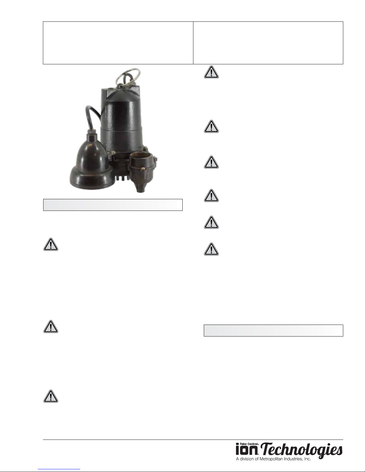
Ion Technologies WC33
Submersible Sump Pump
Safety Warnings
Thank you for purchasing your Ion Technologies
Pump. To help ensure years of trouble-free operation,
please read the following manual carefully.
CAUTION: Read these safety warnings rst
before installing, servicing, or operating any
pump.
Before Installation
This manual contains important information for the
safe use of this product. Read this manual completely
and follow the instructions carefully. Reasonable care
and safe methods relating to the installation and
operation of this product should be practiced. Check
local codes and requirements before installation.
OPERATION MANUAL
Dated: 04/09/2018
Document Name: WC33_OM
Page 1 of 8
WARNING: Risk of Fire or Explosion. Do not
smoke or use open ames in or around this
system. This system is not intended for use in
hazardous locations per NFPA 70 National Electric
Code. Do not pump ammable liquids. Consult factory
for optional equipment rated for hazardous location
use.
WARNING: Cutting Risk. Risk of serious
cutting or amputation exists. Disconnect all
power sources prior to servicing pump. Pump may
start without warning.
CAUTION: Do not modify the cord and plug.
When using the cord and plug, plug into a
grounded outlet only. When wiring to a system control,
connect the pump ground lead to the system ground.
CAUTION: Do not run the pump dry. Dry
running can overheat the pump (causing burns
to anyone handling it) and will void the warranty.
CAUTION: The pump normally runs hot. To
avoid burns, allow it to cool for 30 minutes after
shutdown before handling it.
Submersible sump pumps are not approved
for use in swimming pools, recreational water
installations, decorative fountains or any installation
where human contact with the pumped uid is
common. Pump designed to be installed in a sump or
wet location where drainage collects.
Do not throw away or lose this manual. Keep it in a safe
place so that you may refer to it often for the continued
safe operation of the product.
WARNING: Risk of Electrical Shock or
Electrocution. May result in serious injury or
death or re hazard. Installer must disconnect all
electrical sources prior to installation, handling or
servicing. Only qualied personnel may install this
system. NFPA 70/National Electric Code (NEC) or
local codes must be followed. System must be properly
grounded according to NEC. Do not lift pump by power
cord.
WARNING: Risk of Asphyxiation. Installer(s)
and/or service personnel must use proper
personal protective equipment and follow OSHA 29
CFR 1910.146 or OSHA 29 CFR 1926. Pump may be
installed in a location classied by as a conned space.
www.ionproducts.net
Pump Installation
These important instructions must be followed for
satisfactory performance of your pump. Before
installation, check your local electrical and plumbing
codes.
1. Provide proper sump. Minimum sump diameter
is 18″.
2. Make sure sump is free of string, cloth, nails,
gravel, etc. before installing pump.
3. Do not set pump directly on the bottom of sump
if it is not solid. Raise the pump by placing bricks
or concrete blocks underneath it.
Page 2
Ion Technologies WC33
Submersible Sump Pump
OPERATION MANUAL
Dated: 04/09/2018
Document Name: WC33_OM
Page 2 of 8
4. Use steel or plastic pipe for all connecting lines
between pump and sewer outlet.
Note: Some city regulations do not allow installing a
pump with plastic pipe. Check local regulations.
5. Drill a 1/8″ inch hole into discharge pipe 4 inches
above the pump’s discharge.
6. A check valve should be installed in discharge
pipe, above the cover of the basin.
7. Connect to power source using 3-prong
grounded 115 volt AC receptacle. Do not remove
ground pin from electrical plug. Do not use an
extension cord.
8. Use pump submerged for pumping water-like
liquids (temperature to 120° F).
9. In applications where the pump may sit idle for
months at a time, it is recommended that the
pump(s) be cycled every few months to ensure
the pumping system is working properly when
needed.
10. An audible alarm for high water conditions should
be installed for additional protection against high
water conditions.
Your pump warranty is void...
If...power cord has been cut.
If...pump has been used to pump mud, cement,
tar, abrasives or chemicals.
If...pump has been used for pumping hot water
(above 120°F ).
If...cord tag has been removed.
Note: Automatic thermal overload protects the sealedin-oil motor. Running dry may overheat the motor and
activate the overload protector until the unit cools.
Troubleshooting
Pump does not run or just hums.
1. Line circuit breaker may be o, blown or loose.
2. Cord prong may not be making contact in
receptacle.
3. If all symptoms check okay, motor winding may
be open; take to authorized service center for
check.
Pump runs but does not deliver water.
1. Check valve may be installed backward. Arrow
on valve points in direction of ow.
2. Discharge gate valve, if used, may be closed.
3. Pump may be air locked. Start and stop several
times by plugging and unplugging cord. Check
vent hole in pump case for plugging.
4. Ion Technologies pumps have a small air vent
hole in the impeller cavity to let out trapped air. If
this hole becomes plugged, pump may air lock.
To break the air lock, use a small screwdriver to
clear hole in the impeller cavity.
5. As a secondary precaution in installations of this
type – 1/16″ hole should be drilled in the discharge
pipe below the check valve. The check valve
should be installed in pump discharge above the
cover on the basin.
Note: In sumps where the pump is operating daily, air
locking rarely occurs.
Pump Servicing
Servicing should be performed only by an authorized
service center.
WARNING: Always disconnect the pump from
power source before handling or making any
adjustments. Always wear rubber boots when
there is water on the oor and you must unplug the
pump or make any adjustments.
www.ionproducts.net
1. Pump head may be too high. Pump cannot
deliver water over 24' vertical lift. Horizontal
distance does not aect pumping, except for
friction loss through the pipe.
2. Inlet in pump base may be clogged. Remove
pump and clean out openings.
3. Impeller or volute openings may be plugged or
partially plugged. Remove pump and clean out.
Page 3
Ion Technologies WC33
Head - feet
Capacity - US GPM
0
25
15
5
10
20
30
0 252015105 30 35 40 45
Submersible Sump Pump
OPERATION MANUAL
Dated: 04/09/2018
Document Name: WC33_OM
Page 3 of 8
Pump runs but delivers only small amount of
water.
1. Pump may be air locked. Start and stop several
times by plugging and unplugging cord. Check
vent hole in pump case for plugging.
2. Pump head may be too high. Pump cannot
deliver water over 24' vertical lift. Horizontal
distance does not aect pumping, except loss
due to friction through discharge pipe.
3. Inlet in pump base may be clogged. Remove
pump and clean out openings.
4. Impeller or volute openings may be plugged or
partially plugged. Remove pump and clean out.
5. Pump impeller may be partially clogged causing
motor to run slow, resulting in motor overload.
Clear impeller.
Fuse blows or circuit breaker trips when pump
starts.
1. Inlet in pump base may be clogged. Remove
pump and clean out openings.
2. Impeller or volute openings may be plugged or
partially plugged. Remove pump and clean out.
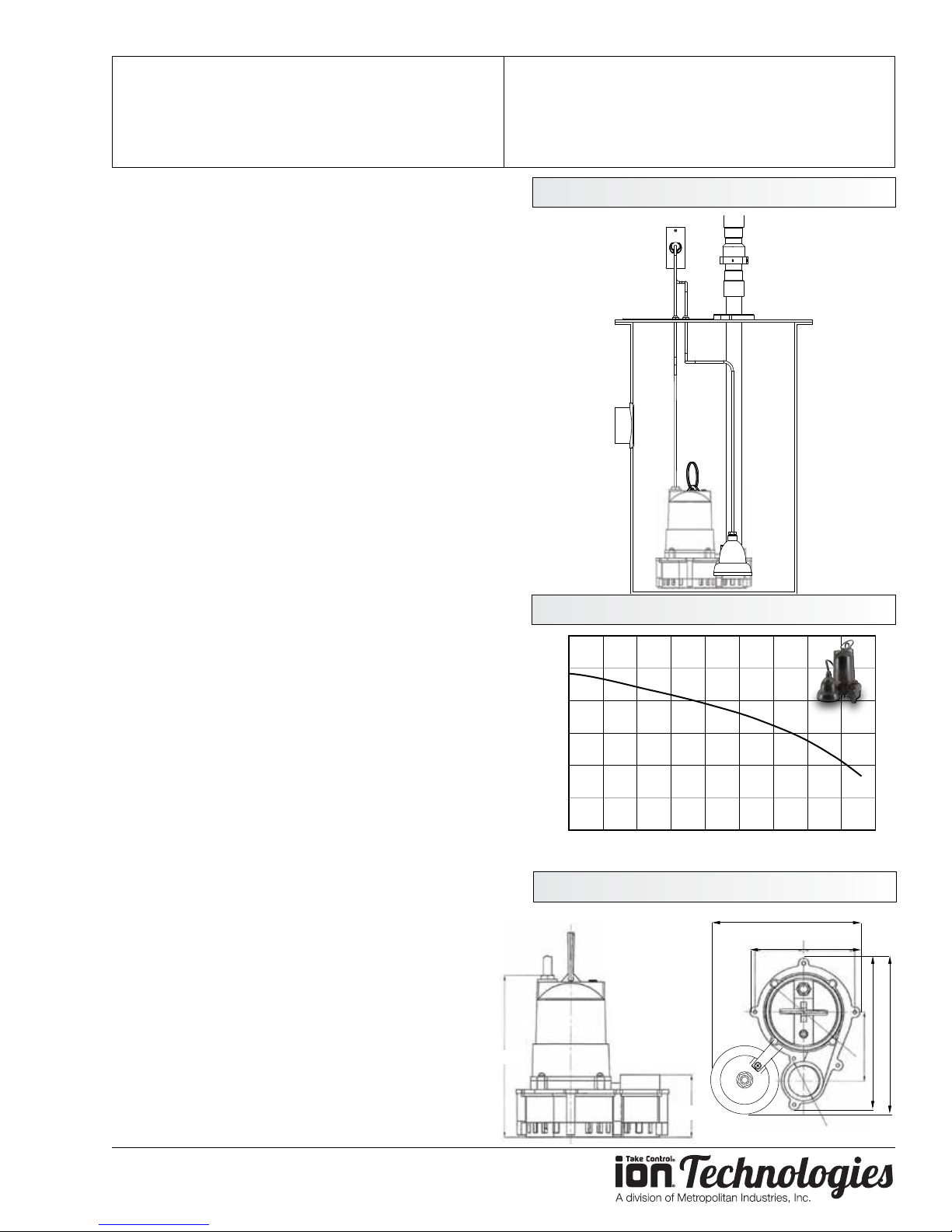
Installation Drawing
Performance
3. Pump impeller may be partially clogged causing
motor to run slow, resulting in motor overload.
Clear impeller.
4. Fuse size or circuit breaker is too small.
5. Defective motor stator; return to authorized
service center for verication.
Motor runs for short time then stops. Then after
short period starts again. Indicates tripping
overload caused by symptom shown.
1. Inlet in pump base may be clogged. Remove
pump and clean out openings.
2. Impeller or volute openings may be plugged or
partially plugged. Remove pump and clean out.
3. Pump impeller may be partially clogged causing
motor to run slow, resulting in motor overload.
Clear impeller.
4. Defective motor stator; return to authorized
service center.
Dimensions
9”
6-1/2”
9-1/2”9”
10”
3-5/8”
1-1/2”
www.ionproducts.net
Page 4
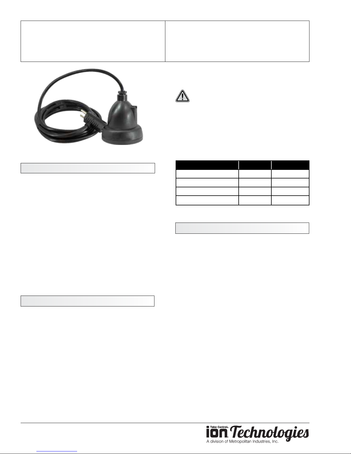
Ion® Digital Level Control
Digital Level Control Switch
Patent pending
OPERATION MANUAL
Dated: 04/09/2018
Document Name: WC33_OM
Page 4 of 8
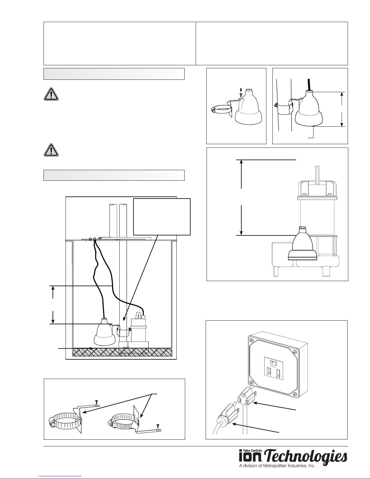
of the switch. From this point, measure up either 6” or
8.5”, depending on your switch’s range, to nd the On
level. Please refer to the Installation Drawing.
CAUTION: Bottom of switch should not be
mounted lower than suction inlet of pump.
When installing the Ion® switch with the pipe mounted
bracket be sure not to set the switch too low or too
high on the pipe. The Ion® must be installed above the
inlet of the pump to prevent air-locking as shown in
the installation drawing.
To prevent ooding do not set the on point of the
switch higher than the top of the basin.
FEATURES
1. First of its kind, solid-state sensing technology
with no moving parts.
2. Space age design with no mechanical
contact points.
3. Multipoint sealing mechanism that supersedes
single surface seals.
4. Inverter rated for use with any battery
back-up system.
5. Standard piggy back connection for use with
any pump.
6. Suitable for sump and sewage applications.
PIPE MOUNTING BRACKET
1. Determine bracket mounting position (Figure
A).
2. Mount bracket to Ion® switch with screw already
provided in Ion® switch (Figure B).
3. Mount Hose Clamp with switch around pipe
at predetermined level. Cable should remain
outside hose clamp (Figure C).
(
OPTIONAL
Model Cord Range
IN-006-010-10PA-B 10 6
IN-085-010-10PA-B 10 8.5
IN-006-020-10PA-B 20 6
IN-085-020-10PA-B 20 8.5
PIGGY
Electrical outlet must not be located in pump pit.
Electrical outlet voltage, piggy-back plug voltage and
pump voltage must all be the same voltage.
DO NOT CUT plug o unit.
Ensure vent tube on plug is protected from moisture,
dirt and insects and other items that could plug or
)
block tube.
1. Insert the Ion® switch’s piggy-back plug into
the outlet.
2. Plug pump into piggy-back plug as (Figure E).
3. Allow system to cycle to ensure proper
installation.
Please note this product may not work in
conjunction with other controllers.
-
ACK INSTALLATION
B
4. Tighten hose clamp.
Note: The Ion® switch is available in 6” or 8.5” ranges.
A 10” range is available for special applications. See
chart for available ranges and cord lengths. The range
of the switch is the distance between the On and O
levels. The O level is at the bracket mounting screw
www.ionproducts.net
Note: The Ion® switch does not operate like a standard
pressure switch. There are no contacts to wear out,
so when pressure is applied, there will not be a click.
Page 5
Ion® Digital Level Control
Digital Level Control Switch
OPERATION MANUAL
Dated: 04/09/2018
Document Name: WC33_OM
Page 5 of 8
SAFETY PRECAUTIONS
CAUTION: To prevent electric shock, ensure
product is connected to a grounded outlet.
The electrical outlet should be properly wired to a
dedicated 15A circuit breaker. Proper short-circuit
and overload protection must be provided at the
distribution panel. Install in accordance with all local
and national electrical codes.
WARNING: Electrical outlet must not be
located in pump pit. For best performance, do
not use electrical extension cords.
INSTALLATION DRAWING
Recommended
1/8” anti-airlocking
Ion® Digital
Level Switch
hole (if not already
provided by pump
manufacturer)
FIGURE B
FIGURE D
Range
of 6”-8.5”
FIGURE C
5”
Ø 3 7/8”
Range
of 6”-8.5”
Lowest
pump
o level
BE SURE TO MOUNT THE ION
FIGURE A
NOTE: If you purchased a pump with the Ion switch
hard-mounted to the pump (Figure D) and the
installation requires the switch be mounted to the
pipe, the pipe-mount bracket is sold separately, PN:
IN-SPB1-1.
FIGURE E
SWITCH AT PROPER LEVEL.
Optional
bracket
Ion® Switch
piggy back
or
Pump plug
www.ionproducts.net
Page 6

Ion® Digital Level Control
Digital Level Control Switch
OPERATION MANUAL
Dated: 04/09/2018
Document Name: WC33_OM
Page 6 of 8
TROUBLESHOOTING
Switch Does Not Turn On Pump
1. Test the pump without the Ion® switch
a. Plug the pump directly into the wall outlet,
without plugging it into the switch plug.
b. If pump still does not run, see the
troubleshooting section in the pump
manual.
c. If the pump does run, continue to the next
step.
2. Test the switch with the pump
a. Plug the pump into the Ion® switch and
plugging the Ion switch plug into the wall.
b. Push up on the sensing plate through the
center hole on the underside of the switch.
Note that, being an electronic switch, you
will not hear a clicking sound.
c. If the pump does not turn on, the switch will
have to be replaced.
d. If the pump does turn on, continue to the
next step.
ii. If the On level is still too high, the switch
will have to be replaced with a lower
range Ion® switch.
c. For a pump-mounted switch, see Page
2, Figure D to verify that the On level is
appropriate for your basin.
i. If the On level is too high, the switch will
have to be replaced with a lower range
Ion switch.
Switch Does Not Turn O Pump
1. Unplug the pump from the Ion® plug and then
unplug the Ion plug from the wall outlet.
2. Plug the pump back into the Ion® plug and plug
the Ion plug back into the wall outlet.
a. If the pump does not turn on right away, and
the water level is not at the On level, let the
pump go through an On / O cycle a few
times to insure that the switch is functioning
properly. The basin may need to be lled
with a garden hose or bucket.
b. If the pump turns on right away, and the
water level is not at the On level, the switch
will have to be replaced.
3. Verify the range of the switch
a. The part number can be found on the
switch cord tag.
i. IN-006… = 6” range
ii. IN-085... = 8.5” range
iii. IN-010… = 10” range (for special
applications)
b. For a pipe-mounted switch, see Page 2,
Installation Drawing to verify that the On
level is appropriate for your basin.
i. Lower the switch on the pipe so the
On level is at a point within the basin,
insuring that the O level does not fall
below the minimum level shown in the
Installation Drawing.
WARRANTY IS VOID IF...
1. Using an extension cord.
2. Power cord has been cut or the grounding
prong removed or using an adapter tting.
3. The switch has been disassembled or tampered
with.
4. Any tags or labels have been removed.
5. Used in a heavy grease application
6. Used in applications exceeding the designed
temperature range of 32 - 104 degrees F.
www.ionproducts.net
Page 7
Ion® Digital Level Control
Digital Level Control Switch
OPERATION MANUAL
Dated: 04/09/2018
Document Name: WC33_OM
Notes Notes
Page 7 of 8
www.ionproducts.net
Page 8

Ion Technologies WC33
Submersible Sump Pump
Ion|StormPro 3 Year Residential Warranty
1. Coverage and Term. Metropolitan Industries, Inc. (“Metropolitan”) warrants to the original
purchaser (the “Buyer”) of each Ion|StormPro product (the “product”), that any part thereof which proves to
be defective in material or workmanship within three (3) years from date of manufacture, will be replaced at
no charge with a new or remanufactured part, F.O.B. factory. Buyer shall be responsible for all freight charges
and all costs of fi eld labor or other charges incurred in the removal and/or reinstallation of any product, part
or component thereof.
2. Exclusions. THE WARRANTY IS SUBJECT TO THE FOLLOWING CONDITIONS AND
EXCLUSIONS:
(a) The Warranty excludes products or workmanship which becomes defective as a result
of: (i) earthquake, fi re, storms, the elements or any other acts of God; (ii) normal wear and tear from use;
(iii) accident, misuse, abuse or neglect; (iv) modifi cations made by Buyer or any third party, other than
Metropolitan; and (v) Buyer’s failure to properly install, maintain, service and/or operate the product under
normal conditions and according to manufacturer’s instructions.
(b) Metropolitan shall not be responsible for, and the Warranty shall not cover, extended
damage which occurs because of Buyer ’s failure to notify Metropolitan promptly in writing of apparent
defects.
(c) Any part or component designated as manufactured by anyone other than Metropolitan
shall be covered only by the express warranty of the manufacturer thereof.
(d) The Warranty shall lapse upon Buyer’s failure to fully comply with the terms and conditions
of its contract with Metropolitan, including Buyer’s failure to pay the purchase price for the product or any
portion thereof. Buyer’s subsequent compliance with the terms and conditions of any such contract, will not
cause the term of the Warranty to extend beyond the time period set forth above.
(e) No actions taken by Metropolitan to correct a defect in a product shall extend the Warranty
beyond the period set forth above. Metropolitan shall not be obligated to remedy any defect, where otherwise
required pursuant to the Warranty unless and until Buyer notifi es Metropolitan in writing of the defect and
then only if such notifi cation is made prior to the expiration of the period set forth above.
3. Process of Claims and Repairs. Metropolitan agrees that if the product or any part or component
thereof shall fail to conform to the terms of this Warranty, Metropolitan shall replace such nonconforming
product, part or component at the original point of delivery and furnish instruction for its disposition. Any
transportation charges involved in such disposition and all costs of fi eld labor or other charges incurred in the
removal and/or reinstallation of any product, part or component thereof shall be the responsibility of Buyer.
4. Limitation on Liability. Notwithstanding any provision to the contrary, Metropolitan’s entire
liability under this Warranty shall not in the aggregate exceed, and Buyer’s exclusive and sole remedies
are, to the extent permitted by law, shall be to secure replacement of the defective product. UNDER NO
CIRCUMSTANCES SHALL METROPOLITAN BE LIABLE UNDER THE WARRANTY FOR
ANY INDIRECT, PUNITIVE, SPECIAL, EXEMPLARY, CONSEQUENTIAL OR INCIDENTAL
DAMAGES (INCLUDING LOST PROFITS, REVENUE, USE OR ECONOMIC ADVANTAGE).
5. Express Waiver of Any Other Warranties. THE EXPRESS WARRANTY SET FORTH IN THIS
WRITTEN WARRANTY IS THE ONLY WARRANTY MADE BY METROPOLITAN, OR ANY OTHER
PARTY, IN CONNECTION WITH ANY PRODUCT PURCHASED FROM METROPOLITAN.
NEITHER METROPOLITAN, NOR ANY OTHER PARTY, MAKES ANY OTHER EXPRESS OR
IMPLIED WARRANTY WHICH IS NOT SET FORTH HEREIN, AND METROPOLITAN HEREBY
DISCLAIMS AND BUYER HEREBY WAIVES ALL IMPLIED WARRANTIES, INCLUDING THE
IMPLIED WARRANTY OF MERCHANTABILITY AND THE IMPLIED WARRANTY OF FITNESS
FOR A PARTICULAR PURPOSE.
6. Not Transferable. The Warranty may not be transferred and shall be void on the sale or other transfer
of the product.
7. Products and Warranty Subject to Change. Metropolitan reserves the right to make revisions to its
products and their specifi cations, and to revise this Warranty and related information without notice.
OPERATION MANUAL
Dated: 04/09/2018
Document Name: WC33_OM
Page 8 of 8
www.ionproducts.net
 Loading...