

Page 1
Ion+® Connect
Digital Level Control Switch With Alarm
Introduction
OPERATION MANUAL
Dated: 07/18/2017
Document Name: Ion+Connect_OM
Page 1 of 12
Features
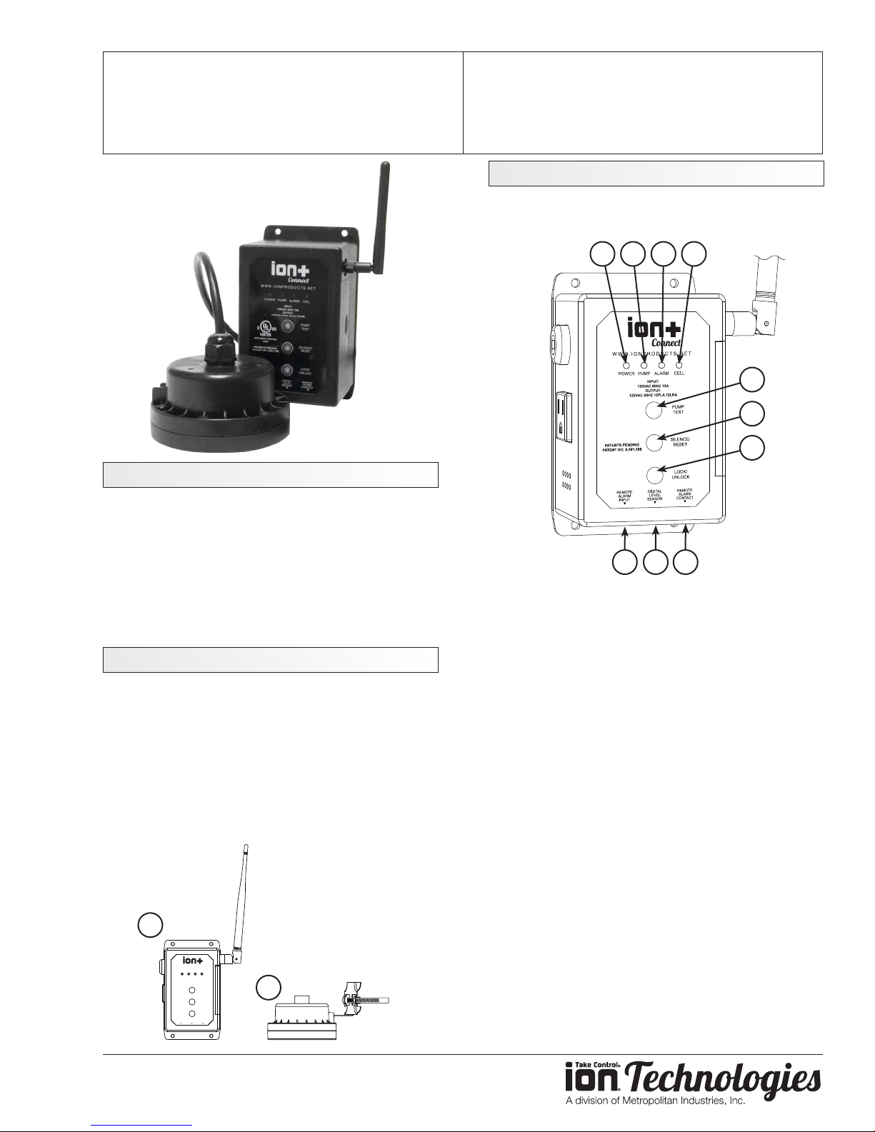
The following illustration describes the physical
features of your Ion+ Connect.
1 2 3 4
5
6
7
The Ion+ Connect is a residential sump/sewage ejector
pump controller equipped with the revolutionary Ion®
level sensor and integrated cellular texting module.
The device will run a manual pump up to 12 FLA,
can sense up to 72” of water, has customizable start/
stop/alarm levels, and provides alarm notications via
SMS text for alarms like high water, pump fail, power
fail, and many more.
What’s in the Box
The Ion+ Connect comes with:
1. Ion+ Connect
Pump Controller equipped with 10’ 115 VAC
15A cord
2. Ion Sensor with pipe clamp
Connects to Ion+ Connect to provide level
signal
10 8 9
1. Power LED
Indicates the power status of unit
Refer to the LED section for details
2. Pump LED
Indicates the pump status
Refer to the LED section for details
3. Alarm LED
Indicates alarm status
Refer to the LED section for details
4. Cell LED
Indicates cellular status
Refer to the LED section for details
5. Pump Test
Hold down button for 5 seconds to manually
run pump
1
Connect
WWW.IONPRODUCTS.NET
POWER PUMP ALARM CELL
INPUT:
120VAC 60HZ 15A
OUTPUT:
120VAC 60HZ 12FLA 72LRA
PUMP
PATENTS PENDING
PATENT NO. 8,591,198
TEST
SILENCE/
RESET
LOCK/
UNLOCK
REMOTE
REMOTE
DIGITAL
ALARM
ALARM
LEVEL
INPUT
CONTACT
SENSOR
2
www.ionproducts.net
6. Silence / Reset
Momentarily push for Alarm Silence
Hold to reset unit
7. Lock / Unlock
Press for approximately 3 seconds to
unlock unit to accept SMS/text conguration
commands
Page 2
Ion+® Connect
Digital Level Control Switch With Alarm
OPERATION MANUAL
Dated: 07/18/2017
Document Name: Ion+Connect_OM
Page 2 of 12
Press again after unlock to lock unit from
accepting SMS/text conguration commands
8. Digital Water Level Sensor
Connection for Ion Sensor
9. Remote Alarm Contact
Normally closed, dry contacts via 6P2C
(RJ14) jack
10. Remote Alarm Input
Aux alarm input connection via 6P2C (RJ14)
jack
Installation
NOTE: IF YOU ARE INSTALLING THE ION+
CONNECT WITH AN EXISTING SUMPRO MODEL
75, PLEASE CONTACT MANUFACTURER FIRST.
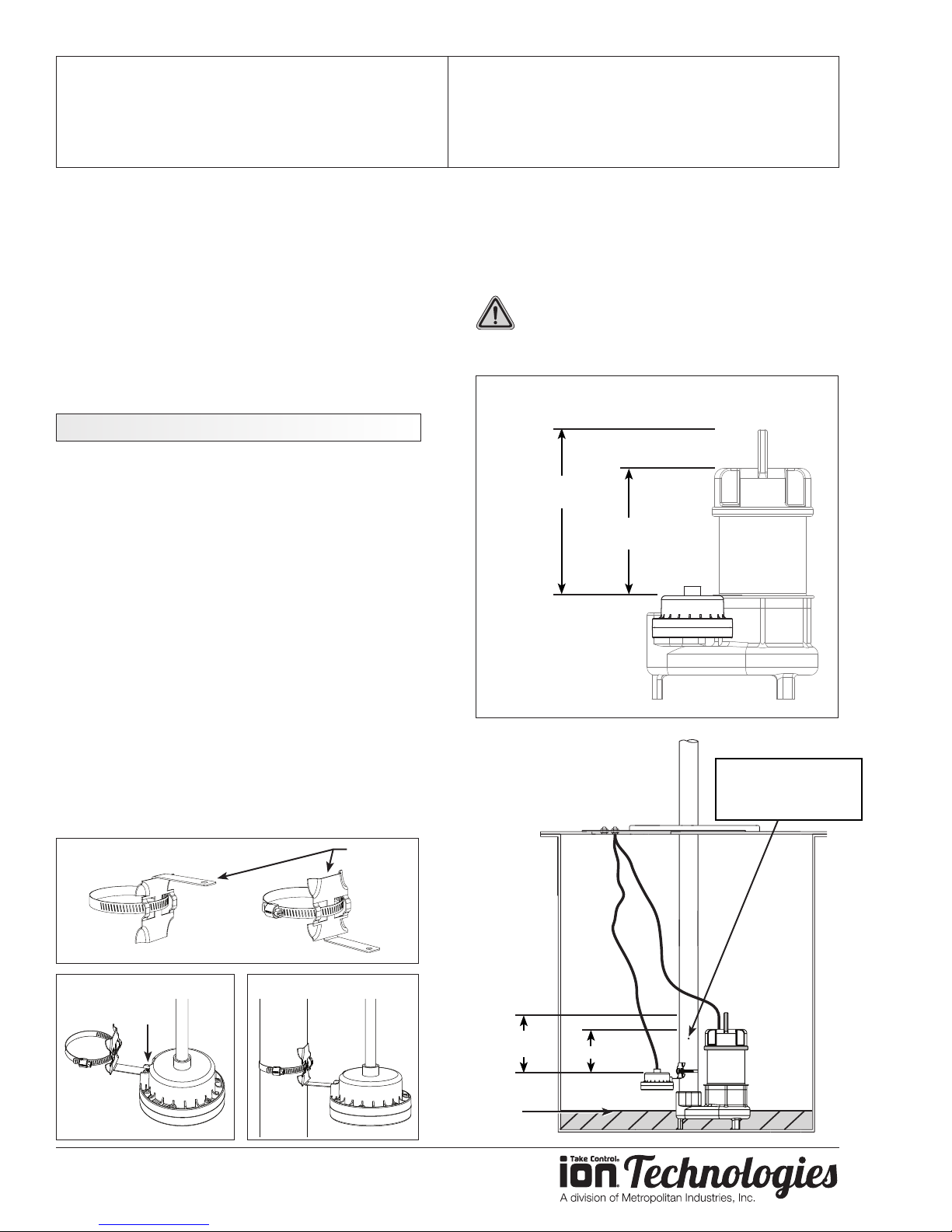
1. Install Ion+ Connect and Ion Sensor
a. Mount Ion+ Connect unit to wall with appropriate
screws (not included).
b. Determine bracket mounting orientation (Figure
A).
f. Plug pump and Ion Sensor into Ion+ Connect.
Note: The included Ion digital water level sensor has
a 72” range. The range of the sensor is the distance
between the pump on and o levels. The o level is at
the bracket mounting screw of the sensor.
CAUTION: Bottom of sensor should not be
mounted lower than suction inlet of pump.
When installing the Ion sensor with the pipe mounted
bracket be sure not to set the sensor too low or too
FIGURE D
Factory default settings
User adjustable up to 72”
8" High Water
Alarm
6" Range
On
c. Mount bracket to Ion sensor with screw already
provided in Ion sensor (Figure B).
d. Mount hose clamp with switch around pipe
at predetermined level. Cable should remain
outside hose clamp (Figure C). Tighten hose
clamp.
e. Pull pump power cord and Ion sensor cord
through pit lid.
FIGURE A
Optional
bracket
or
FIGURE B
FIGURE C
Ion Sensor
Installation Diagram
8" High Water
Alarm
6” Range On
(factory default)
Lowest
pump
o level
Recommended
1/8” anti-airlocking
hole
www.ionproducts.net
Page 3
Ion+® Connect
Digital Level Control Switch With Alarm
OPERATION MANUAL
Dated: 07/18/2017
Document Name: Ion+Connect_OM
Page 3 of 12
high on the pipe. The Ion sensor must be installed
above the inlet of the pump to prevent air-locking as
shown in the installation diagram.
To prevent ooding do not set the on point of the
pump higher than the top of the basin.
NOTE: If you purchased a pump with the sensor
already mounted to the pump (Figure D) and the
installation requires the sensor be mounted to the
pipe, the pipe-mount bracket is sold separately, PN:
IN-SPB1-1.
2. Setup Your Cell Phone
The Ion+ Connect has a phone number associated
to it and its number should be added to your phone’s
contacts.
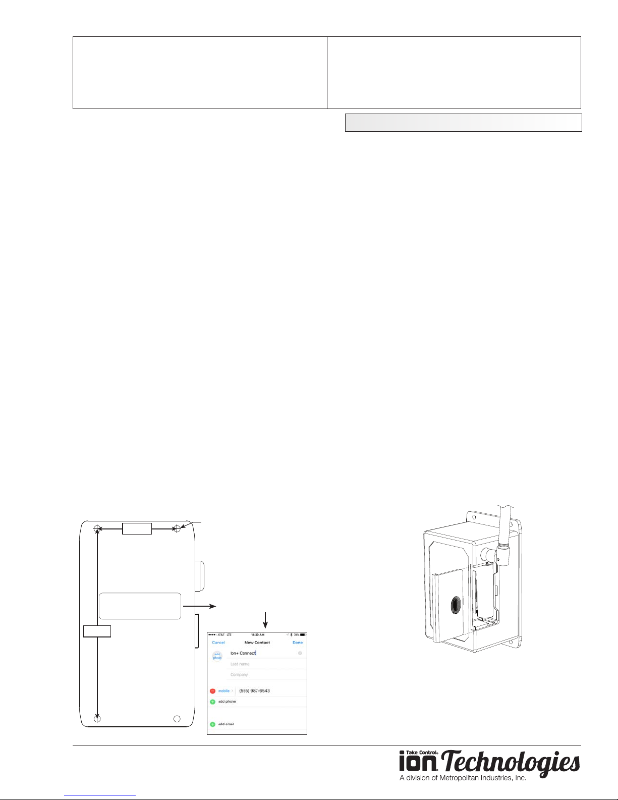
a. Take note of the Ion+ Connect’s phone number
located on the housing.
b. Add the phone number of your Ion+ Connect’s
to the contact list of your cell phone.
Refer to the user’s manual of your cell phone
for more details on how to add a new contact:
1. Create a new contact.
2. Enter a name for the contact such as “Ion+
Connect”.
3. Enter the phone number of the Ion+
Connect for the contact.
Configuration
NOTE: Do not install the lithium ion battery until
the Ion+ Connect unit has been plugged into AC
power and is powered on.
1. Power On, Congure, Test
Plug the Ion+ Connect into a dedicated AC outlet.
Once it is powered on, the Ion+ Connect will attempt
to connect to the cellular network.
a. Wait for the Cell light to turn solid green; this
can take up to 1 minute.
b. The Cell light may briey turn red. If the Cell
light turns red for more than 1 minute, refer to
the Troubleshooting section of this manual.
2. Install Lithium Ion Battery
The Ion+ Connect comes with a rechargeable lithium
ion battery to provide backup power in times of power
loss in order to continue to send out alarm notications
and operate the beeper. NOTE: This battery will not
run your pump.
a. Remove the slide cover on right edge of unit.
b. Install battery as shown, observing proper
orientation/polarity (positive battery terminal/
button toward top).
2-3/16”
Phone #: (555) 987-6543
Serial #: 123456789
5-5/8”
(4) 3/16” Dia.
Mounting Holes
www.ionproducts.net
Phone #: (555) 987-6543
3. Unlock the Ion+ Connect
The Ion+ Connect must be unlocked each time before
it will allow you to congure it via its Administrator
Settings (see the Commands Summary section).
Page 4
Ion+® Connect
Digital Level Control Switch With Alarm
a. Press and hold the “Unlock/Lock” button for
approximately 3 seconds until it beeps twice.
b. The Cell LED will begin to blink red and amber.
NOTE: The Ion+ Connect will stay in conguration
mode for up to 5 minutes, or until you press the
“Unlock/Lock” button.
4. Congure Notication Phone Numbers
The Ion+ Connect will send notications to up to
10 dierent phone numbers. The phone numbers
are congured by sending the Ion+ Connect text
messages from your cell phone. You must congure
at least one phone number for text messaging
notications.
a. Using your cell phone, compose a new text
message to the Ion+ Connect contact added
earlier.
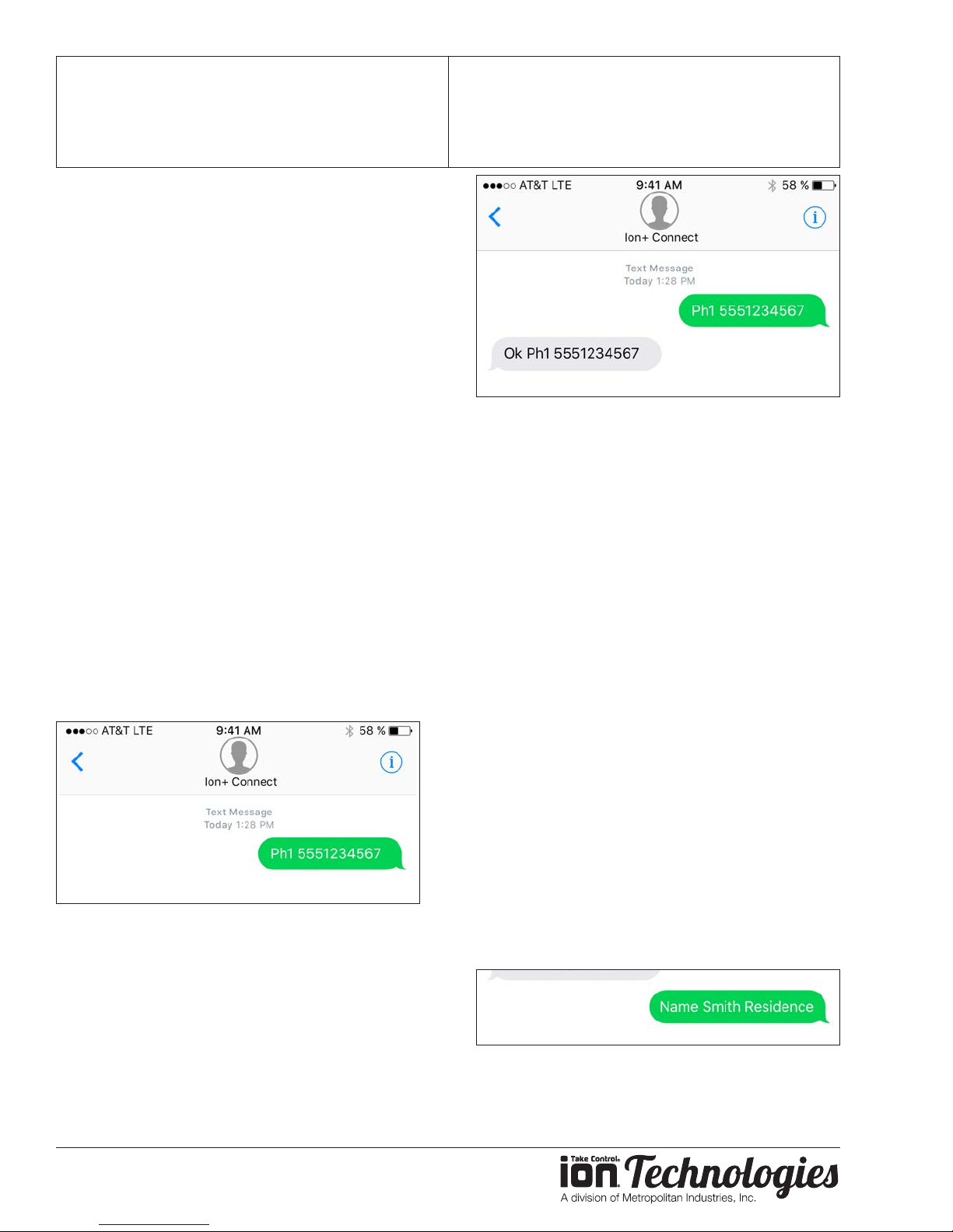
b. Send a text message to your Ion+ Connect
formatted as follows:
Ph1 [Your Cell Phone Number]
Example: Ph1 5551234567
NOTE: The phone number must be 10 digits
long, which includes the area code.
OPERATION MANUAL
Dated: 07/18/2017
Document Name: Ion+Connect_OM
Page 4 of 12
d. Repeat these steps for up to nine other phone
numbers:
Ph2 [Phone Number To Add]
Ph3 [Phone Number To Add]
Ph4 [Phone Number To Add]
Ph5 [Phone Number To Add]
Ph6 [Phone Number To Add]
Ph7 [Phone Number To Add]
Ph8 [Phone Number To Add]
Ph9 [Phone Number To Add]
Ph10 [Phone Number To Add]
NOTE: These commands must be individual
text messages -- you cannot combine multiple
commands in one text message.
c. When the Ion+ Connect receives the message,
it will respond with a text message conrming
that the phone number was successfully added.
You should wait for the text message response
on your phone before proceeding.
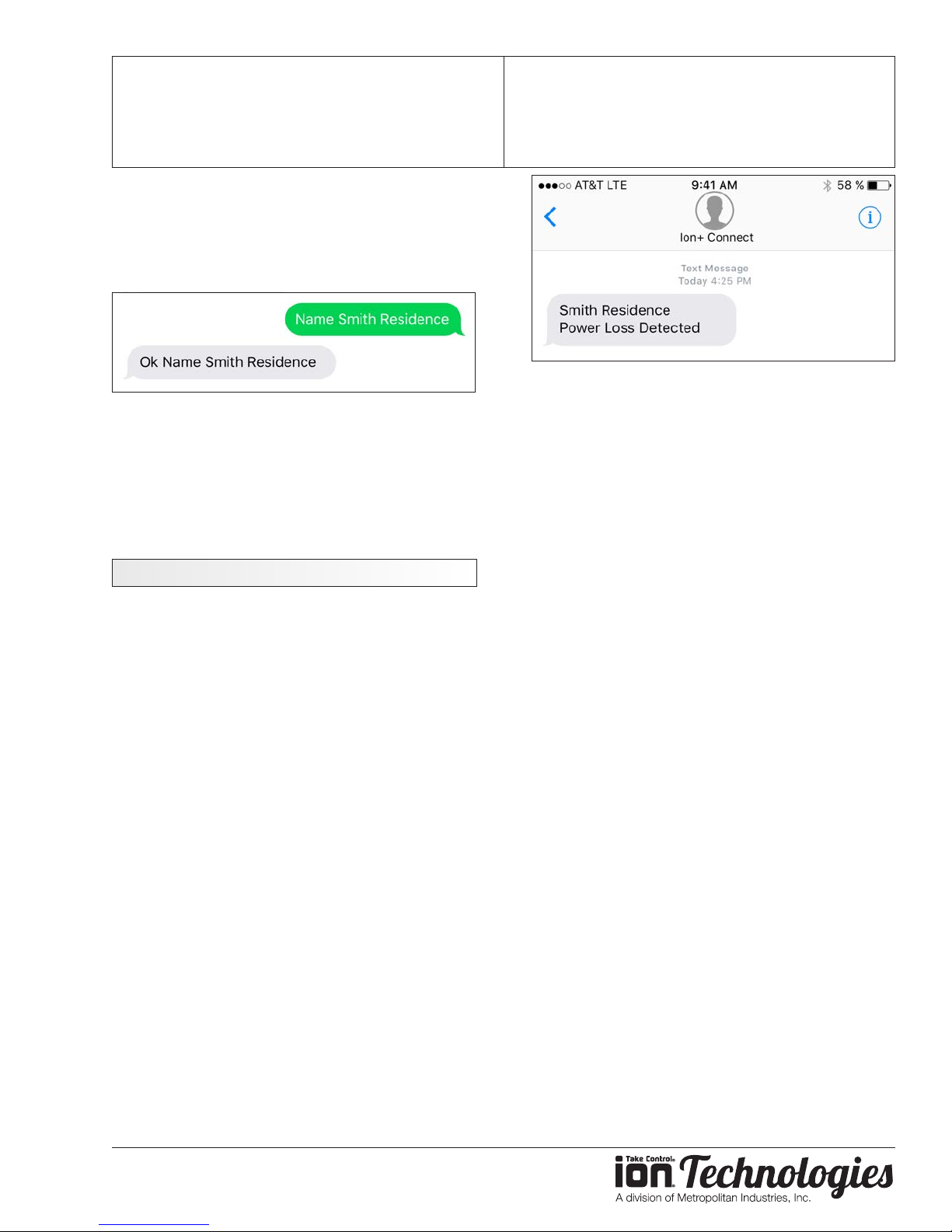
5. Congure the Name of Your Ion+ Connect
You can give your Ion+ Connect a name that it uses
in the notication messages it sends.
a. On your cell phone, compose a new text
message to your Ion+ Connect’s phone number .
b. Send a text message to your Ion+ Connect
formatted as follows:
Name [Name]
Example: Name Smith Residence
www.ionproducts.net
Page 5
Ion+® Connect
Digital Level Control Switch With Alarm
3. When the Ion+ Connect receives the message,
it will it will respond with a text message
conrming that the name was set.
You should wait for the text message response
on your phone before proceeding.
6. Exit Conguration Mode
Conguration is complete, so you can exit
conguration mode.
a. Press the “Unlock/Lock” button.
b. The Cell light will stop blinking red and amber.
Testing Your Ion+ Connect
1. T est Your Pump
You can test your Ion+ Connect at any time by
pressing the “Pump Test” button.
OPERATION MANUAL
Dated: 07/18/2017
Document Name: Ion+Connect_OM
Page 5 of 12
c. Plug the AC power adapter back into the 120
VAC outlet.
NOTE: The backup battery requires approximately 6
hours to fully recharge. The battery has a lifespan of
up to 3 years and should be replaced regularly.
4. Testing is Complete
a. Your Ion+ Connect has been tested and is
working properly.
b. You should periodically perform these tests on
the Ion+ Connect to ensure you are always
protected.
a. Holding Pump Test will manually run pump.
b. Holding it for 3 seconds will send a notication
to those in the list.
2. Test Your Ion Sensor
a. Fill the sump pit with water.
b. Conrm the water is pumped out of the pit. No
alarms or text mesages should be initiated.
3. Test Your Backup Battery
a. Unplug the AC power adapter from the 120
VAC outlet.
b. Once the Ion+ Connect detects that power was
lost, each phone number you congured will
receive a notication text message.
www.ionproducts.net
Page 6
Ion+® Connect
Digital Level Control Switch With Alarm
OPERATION MANUAL
Dated: 07/18/2017
Document Name: Ion+Connect_OM
Page 6 of 12
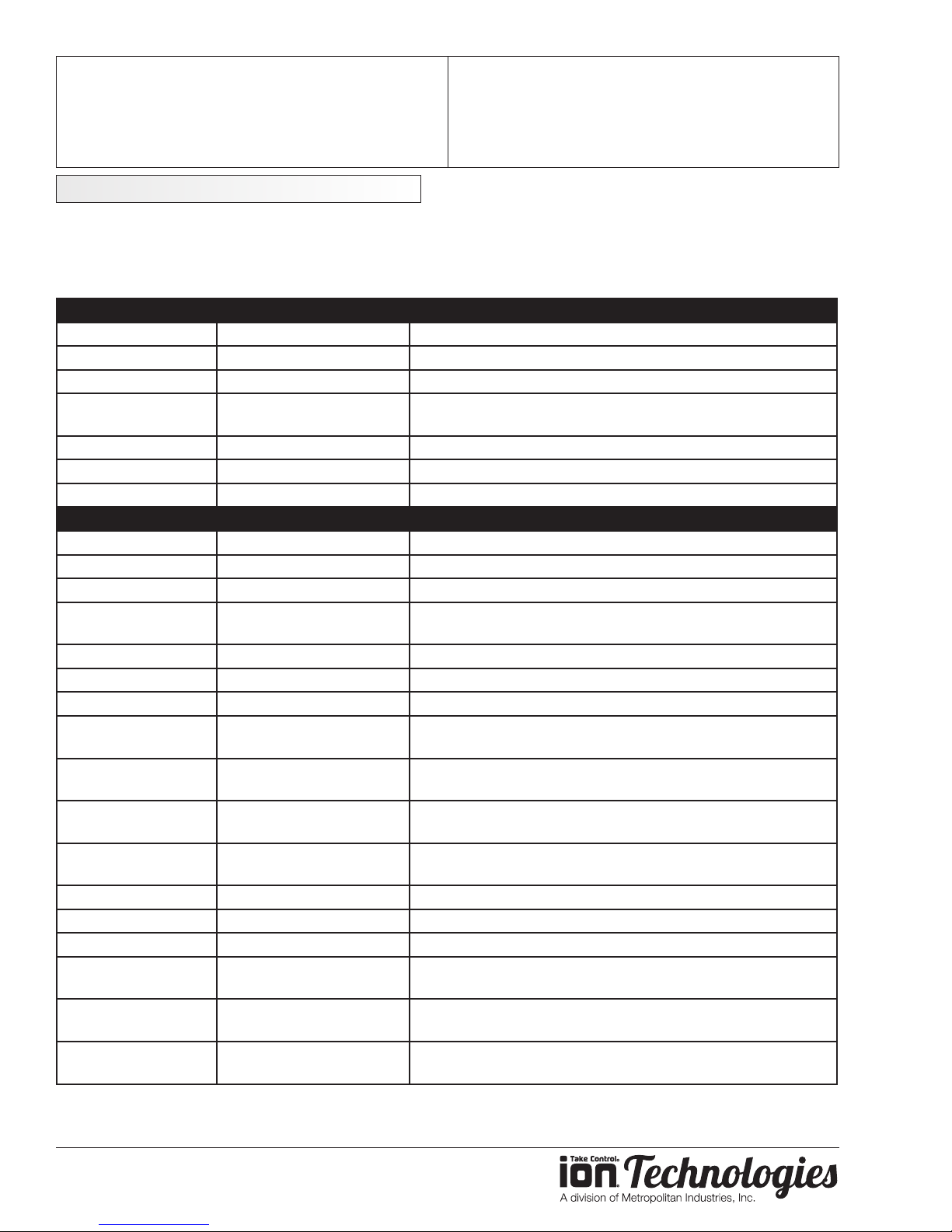
Commands Summary
These are the commands accepted by the Ion+ Connect. Note that the commands under the Admin Settings
section will only be accepted if the unit is rst unlocked by holding the UNLOCK button on the faceplate until it beeps
twice. To see the current numeric value of an administrator setting, unlock the unit, then send the command with a
question mark at the end of it (e.g., pump start?).
Command Syntax Description
ph list ph list Responds with list on phone numbers in list
settings settings Responds with settings
status status Responds with status
pump test pump test Run pump test and send result SMS to the phone number
water water Responds with current water level in inches above sensor
temp temp Responds with room temperature in degrees Fahrenheit
batt batt Responds with Ion+ Connect’s battery’s voltage
name name Wayne's Basement Sets description of unit location
ph1 ph1 7778889999 Sets rst phone number to notify
ph1 clear Clears phone number
Same as above for
10 phone numbers
alert mode alert mode alert Noties all phone numbers at once - no acknowledgments
alert mode dialer Noties phone numbers one at time - acknowledgements*
alert delay alert delay 5 In alert mode - Sets time in Minutes between sending alerts
alert suppress alert suppress 12 In dialer mode - Sets time in Hours to reactivate a previously
alert suppress 0 In dialer mode - Disable suppression timer feature
alarm delay alarm delay 15 Sets the time in Seconds that alarm must exist for before
pump start pump start 6.0 Sets the value in inches for level to start the pump running
pump stop pump stop 2.0 Sets the value in inches for level to stop the pump running
alarm current high alarm current high 10 Sets the value in Amps that will trigger pump fail alarm
alarm current low alarm current low 1 Sets the value in amps that will detect pump as being on or
alarm power restore alarm power restore 30 Sets the value in Secs for before power fail clears and
alarm batt critical alarm batt critical 3.5 Sets the value in volts for critical low battery threshold (unit
which sent the command only
ADMIN SETTINGS
In dialer mode - Sets time in Minutes before sending alert to
next ph in list. Allows time for user acknowledgment.
acknowledged alarm that has yet to clear
(acknowledged alarms stay acknowledged)
sending alert
disconnected
power is deemed to be restored
is about to die)
*When the text alert mode is set to “dialer”, simply replying to incoming alerts with a copy of the received alert will
acknowledge it, silencing the alarm and preventing others from receiving the same text alert.
www.ionproducts.net
Page 7
Ion+® Connect
Digital Level Control Switch With Alarm
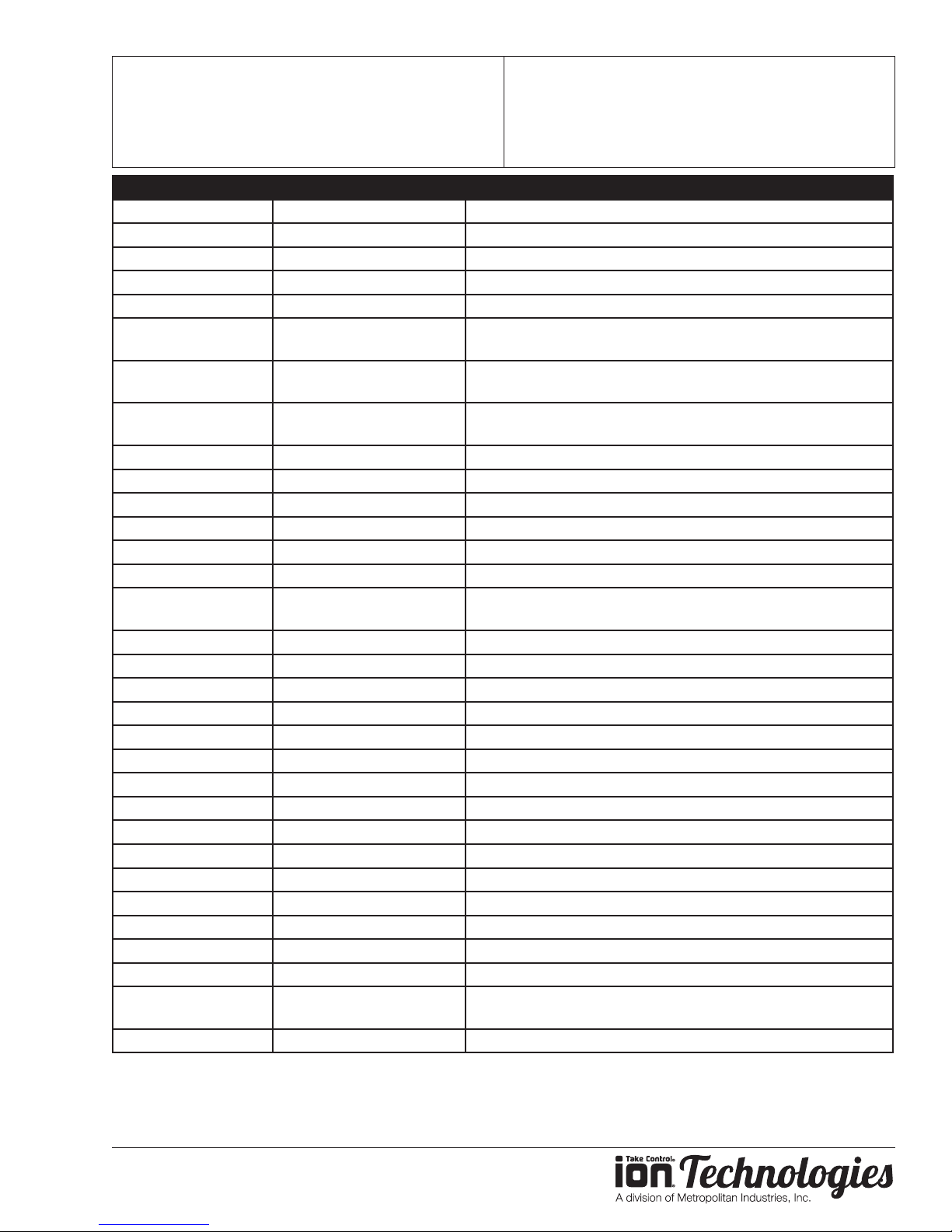
Command Syntax Description
alarm batt low alarm batt low 3.9 Sets the value in volts for low battery threshold
alarm level high alarm level high 8 Sets the value in inches for high level threshold
alarm level low alarm level low 0 Sets the value in inches for low level threshold
alarm temp low alarm temp low 45 Sets the Value in Fahrenheit for low temp alarm threshold
alarm temp high alarm temp high 110 Sets the Value in Fahrenheit for high temp alarm threshold
alarm comm attempt alarm comm attempt 10 Sets the value of attempts to make to cell provider before
alarm comm cloud alarm comm cloud 10 Sets the value of for number of ACKs missed from cloud
alarm relay out alarm relay out common
(default)
alarm relay out run Relay output based on pump running
alarm relay out pump Relay output based on pump fail
alarm relay out level Relay output based on level related alarm conditions
alarm relay out temp Relay output based on temp related alarm conditions
alarm relay out batt Relay output based on battery related alarm conditions
alarm relay out power Relay output based on power related alarm conditions
alarm relay out loss Relay output based on communication related alarm
alarm relay out unlock Relay output based on device being unlocked
alarm relay out input Relay output based on remote input
alarm relay out nc Change relay output to normally closed
alarm relay out no Change relay output to normally open
alert en/dis alert en common (default) Enable / Disable common alert
alert en run / alert dis run Enable / Disable pump running
alert en pump Enable / Disable pump fails
alert en level Enable / Disable level alerts
alert en temp Enable / Disable temp alerts
alert en batt Enable / Disable battery alerts
alert en power Enable / Disable power alerts
alert en unlock Enable / Disable unlock alert
alert en input Enable / Disable remote input alerts
alarm relay in alarm relay in no Change remote input to normally open
alarm relay in nc Change remote input to normally closed
alarm relay in desc alarm relay in desc
Remote alarm is on
factory default factory default Set all settings to their factory default values
OPERATION MANUAL
Dated: 07/18/2017
Document Name: Ion+Connect_OM
Page 7 of 12
issuing alarm (LED)
before alarm (LED on device, alert from cloud)
Relay output based on common alarm
conditions
Changes description in SMS message related to alarm input
www.ionproducts.net
Page 8
Ion+® Connect
Digital Level Control Switch With Alarm
OPERATION MANUAL
Dated: 07/18/2017
Document Name: Ion+Connect_OM
Page 8 of 12
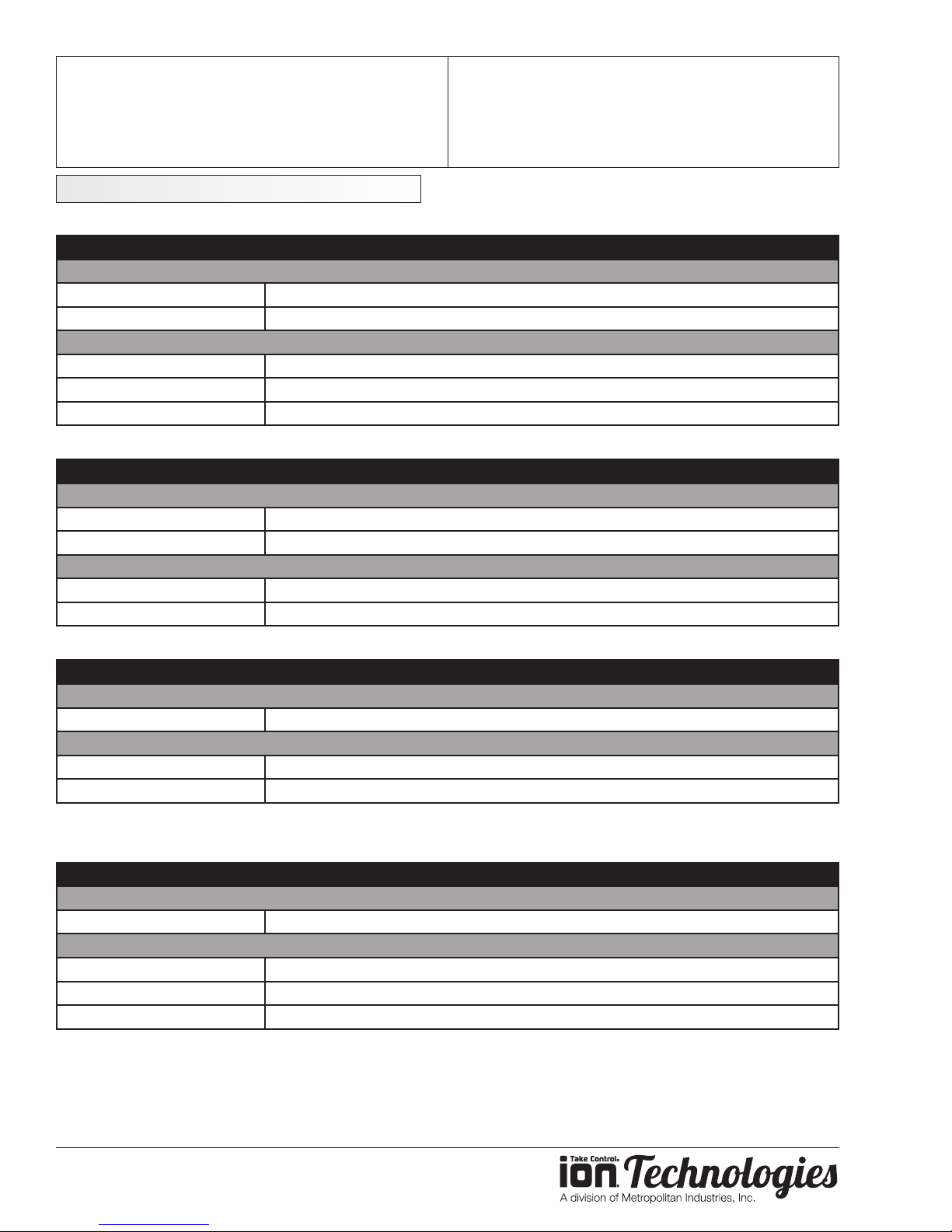
LED Explanations
Power LED
Condition
Normal
battery ok, AC ok Solid GREEN
battery charging, AC ok Blinking GREEN (1s on, 1s o)
Trigger alarm
Loss of power Blinking AMBER (0.1s on, 0.9s o)
battery low Alternate blinking AMBER and RED (RED ON, GREEN 0.5s on, 1.5s o)
battery critically low Blinking RED (0.1s on, 0.9s o)
Pump LED
Condition
Normal
pump o O
pump on Solid AMBER
Trigger alarm
no pump Blinking AMBER (0.5s on, 0.5s o)
pump fail Blinking AMBER (1s on, 1s o)
Alarm LED
Condition
Normal
no alarm O
Triggered alarm
alarm Fast-blinking RED (0.3s on, 0.3s o) w/ Buzzer
silence Slow-blinking RED (1s on, 1s o) w/o Buzzer
Buzzer interval same as fast-blinking RED (0.3s on, 0.3s o)
Cell LED
Condition
Normal
locked, good signal strength Solid GREEN
Triggered alarm
locked, low signal strength Solid AMBER
locked, not in network Solid RED
unlocked Alternate Blinking AMBER and RED (RED LED on, GREEN 1s on, 1s o)
www.ionproducts.net
Page 9
Ion+® Connect
Command Summary).
Digital Level Control Switch With Alarm
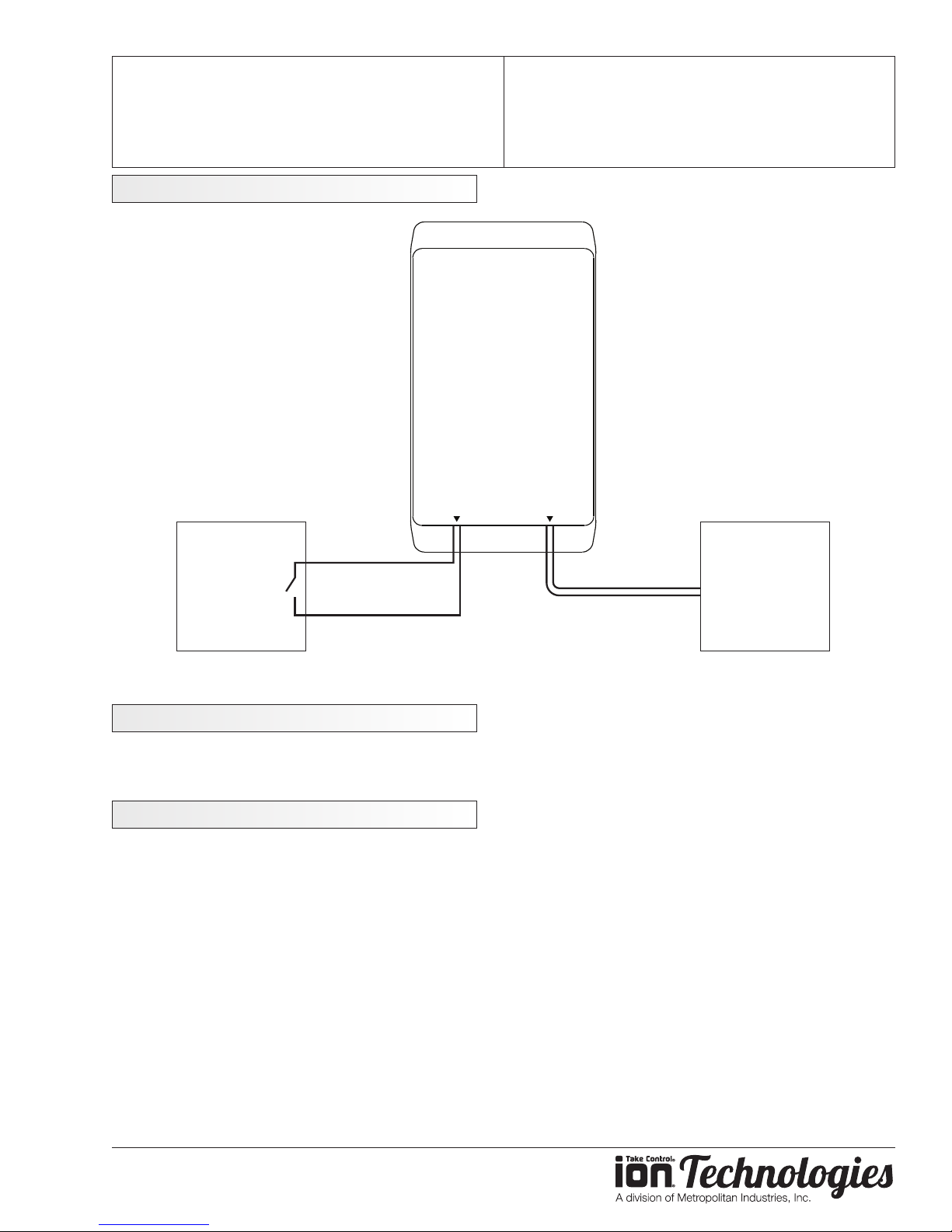
Optional External Connections
Ion+ Connect
OPERATION MANUAL
Dated: 07/18/2017
Document Name: Ion+Connect_OM
Page 9 of 12
Optional
External
Device to
be Monitored
by Ion+ Connect
Remote
Alarm
Input
Two centermost
pins, maximum
5 VDC, < 2 mA
Either circuit inside the Ion+ Connect may be configured via
cellular phone to be normally open or normally closed (see
Remote
Alarm
Contact
Two centermost
pins, maximum
30 VAC/DC, 1 A
Optional
External
Alarm System
to Monitor
Ion+ Connect
15.21 Information to User
Changes or modications not expressly approved by Metropolitan Industries will void the user’s authority to operate
the equipment.
15.105 Information to User
NOTE: This equipment has been tested and found to comply with the limits for a Class A digital device, pursuant to
part 15 of the FCC Rules. These limits are designed to provide reasonable protection against harmful interference
when the equipment is operated in a commercial environment. This equipment generates, uses, and can radiate
radio frequency energy and, if not installed and used in accordance with the instruction manual, may cause harmful
interference to radio communications. Operation of this equipment in a residential area is likely to cause harmful
interference in which case the user will be required to correct the interference at his own expense.
www.ionproducts.net
Page 10
Ion+® Connect
Digital Level Control Switch With Alarm
Notes
OPERATION MANUAL
Dated: 07/18/2017
Document Name: Ion+Connect_OM
Page 10 of 12
www.ionproducts.net
Page 11
Ion+® Connect
Digital Level Control Switch With Alarm
Notes
OPERATION MANUAL
Dated: 07/18/2017
Document Name: Ion+Connect_OM
Page 11 of 12
www.ionproducts.net
Page 12

Ion+® Connect
Digital Level Control Switch With Alarm
1. Coverage and Term. Metropolitan Industries, Inc. (“Metropolitan”) warrants to the original
purchaser (the “Buyer”) of each Ion Technologies product (the “product”), that any part thereof which proves
to be defective in material or workmanship within one (1) year from date of manufacture, will be replaced at
no charge with a new or remanufactured part, F .O.B. factory. Buyer shall be responsible for all freight charges
and all costs of fi eld labor or other charges incurred in the removal and/or reinstallation of any product, part
or component thereof.
2. Exclusions. THE WARRANTY IS SUBJECT TO THE FOLLOWING CONDITIONS AND
EXCLUSIONS:
(a) The Warranty excludes products or workmanship which becomes defective as a result
of: (i) earthquake, fi re, storms, the elements or any other acts of God; (ii) normal wear and tear from use;
(iii) accident, misuse, abuse or neglect; (iv) modifi cations made by Buyer or any third party, other than
Metropolitan; and (v) Buyer’s failure to properly install, maintain, service and/or operate the product under
normal conditions and according to manufacturer’s instructions.
(b) Metropolitan shall not be responsible for, and the Warranty shall not cover, extended
damage which occurs because of Buyer’s failure to notify Metropolitan promptly in writing of apparent
defects.
(c) Any part or component designated as manufactured by anyone other than Metropolitan
shall be covered only by the express warranty of the manufacturer thereof.
(d) The Warranty shall lapse upon Buyer’s failure to fully comply with the terms and conditions
of its contract with Metropolitan, including Buyer’s failure to pay the purchase price for the product or any
portion thereof. Buyer’s subsequent compliance with the terms and conditions of any such contract, will not
cause the term of the Warranty to extend beyond the time period set forth above.
(e) No actions taken by Metropolitan to correct a defect in a product shall extend the W arranty
beyond the period set forth above. Metropolitan shall not be obligated to remedy any defect, where otherwise
required pursuant to the Warranty unless and until Buyer notifi es Metropolitan in writing of the defect and
then only if such notifi cation is made prior to the expiration of the period set forth above.
3. Process of Claims and Repairs. Metropolitan agrees that if the product or any part or component
thereof shall fail to conform to the terms of this Warranty, Metropolitan shall replace such nonconforming
product, part or component at the original point of delivery and furnish instruction for its disposition. Any
transportation charges involved in such disposition and all costs of fi eld labor or other charges incurred in the
removal and/or reinstallation of any product, part or component thereof shall be the responsibility of Buyer.
4. Limitation on Liability. Notwithstanding any provision to the contrary, Metropolitan’s entire
liability under this Warranty shall not in the aggregate exceed, and Buyer’s exclusive and sole remedies
are, to the extent permitted by law, shall be to secure replacement of the defective product. UNDER NO
CIRCUMSTANCES SHALL METROPOLITAN BE LIABLE UNDER THE WARRANTY FOR
ANY INDIRECT, PUNITIVE, SPECIAL, EXEMPLARY, CONSEQUENTIAL OR INCIDENTAL
DAMAGES (INCLUDING LOST PROFITS, REVENUE, USE OR ECONOMIC ADVANTAGE).
5. Express Waiver of Any Other Warranties. THE EXPRESS WARRANTY SET FORTH IN THIS
WRITTEN W ARRANTY IS THE ONL Y W ARRANTY MADE BY METROPOLIT AN, OR ANY OTHER
PARTY, IN CONNECTION WITH ANY PRODUCT PURCHASED FROM METROPOLITAN.
NEITHER METROPOLITAN, NOR ANY OTHER PARTY, MAKES ANY OTHER EXPRESS OR
IMPLIED WARRANTY WHICH IS NOT SET FORTH HEREIN, AND METROPOLITAN HEREBY
DISCLAIMS AND BUYER HEREBY WAIVES ALL IMPLIED WARRANTIES, INCLUDING THE
IMPLIED WARRANTY OF MERCHANTABILITY AND THE IMPLIED WARRANTY OF FITNESS
FOR A PARTICULAR PURPOSE.
6. Not Transferable. The Warranty may not be transferred and shall be void on the sale or other transfer
of the product.
7. Products and Warranty Subject to Change. Metropolitan reserves the right to make revisions to its
products and their specifi cations, and to revise this Warranty and related information without notice.
OPERATION MANUAL
Dated: 07/18/2017
Document Name: Ion+Connect_OM
Page 12 of 12
1 Year Residential Warranty
www.ionproducts.net
 Loading...