

Page 1
iTT03X
CONTENIDO DE LA CAJA
Portacápsulas
BOX CONTENTS
Fonorivelatore
CONTENU DE LA BOÎTE
COQUILLE
INHALT DER VERPACKUN
G
Tonkopfgehäuse
BOX CONTENTS
Headshell
PROFESSIONAL
TURNTABLE
Quick Start Owner’s Manual
§ Main Unit
§ Turntable platter
§ Turntable slip mat
§ Dust cover
§ (2) Dust cover clips
§ 45-rpm adapter
§ Counterweight
§
Manual de inicio rápido para el usuario (ESPAÑOL)
§ Unidad principal
§ Plato del giradiscos
§ Patinador del giradiscos
§ Cubierta antipolvo
§ (2) clips para cubierta antipolvo
§ Adaptador de 45rpm
§ Contrapeso
§
Schnellbedienungsanleitung (DEUTSCH)
• Gerät
• Plattenteller
• Slipmat für Plattenteller
• Abdeckhaube
• (2) Klammern für Abdeckhaube
• 45-Rpm Mittelstück
• Gegengewicht
•
Manuel d’utilisation du propriétaire (FRANÇAIS)
• APPAREIL
• PLATEAU DU TOURNE-DISQUE
• TAPIS
• COUVERCLE ANTI-POUSS#ERE
• (2) FIXATIONS DU COUVERCLE ANTI-POUSSI#ERE
• ADAPTATEUR 45 RPM
• CONTREPOIDS
•
Manuale rapido di utilizzazione (ITALIANO)
• Unità Principale
• Piatto del Giradischi
• Base del Giradischi
• Copertura antipolvere
• (2) Clip della copertura antipolvere
• Adattatore 45 giri
• Contrappeso
•
Page 2
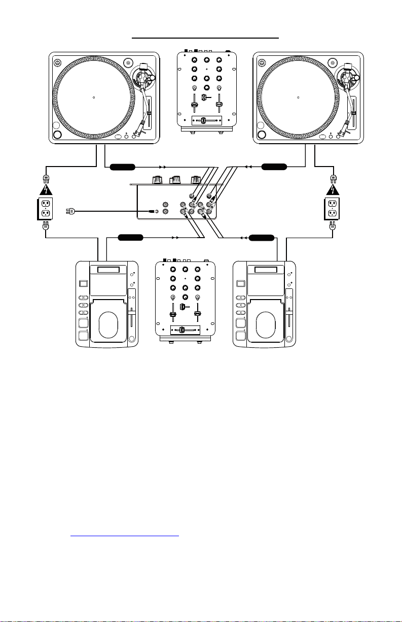
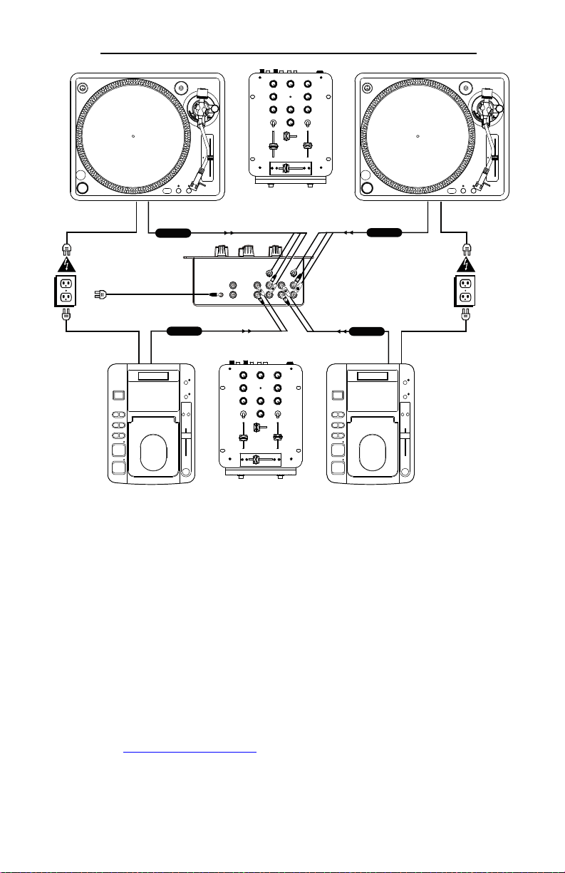
QUICK SETUP GUIDE (ENGLISH)
TO PHONOTO PHONO
TO LINETO LINE
1. Make sure all items listed on the front of this guide are included in the box.
2. READ SAFETY INSTRUCTION BOOKLET BEFORE USING THE PRODUCT
3. Study this setup diagram.
4. Place product in an appropriate position for operation.
5. Make sure all devices are turned off and all faders are at “zero”
6. Connect all stereo input sources as indicated in the diagram.
7. Connect the stereo outputs to the power amplifier(s), tape decks, and/or audio
sources.
8. Plug your mixer and other devices into AC power.
9. Switch everything on in the following order.
· audio input sources (i.e. turntables or CD players)
· your mixer
· last, any amplifiers
10. When turning off, always reverse this operation by,
• turning off amplifiers
• your mixer
• last, any input devices
11. Go to http://www.ion-audio.com for product registration.
Page 3
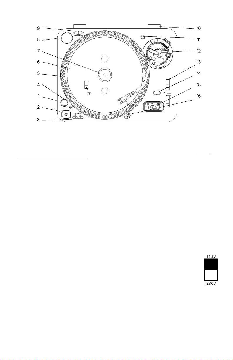
DIAGRAM AND PARTS DESCRIPTION
you begin operation. The ITT03X should be placed on a level sturdy surface. Keep in mind that
there are a few features you may never have seen before on a turntable of this type that you
will need to read about to use properly.
check all packing material for hidden parts. Use the contents guide for reference. Do not
discard any packing materials!
1. Power Dial
2. START/STOP - Pressing once
3. Platter Revolution Speed Buttons
4. Strobe Light - Pulses a beam of light
5. Strobe Dots - Four rows of dots that
6. Platter - Place this on the Center
7. Center Spindle - Keeps platter and
8. 45 Adapter - Place on Center Spindle
9. Forward/Reverse Buttons -
10. Lid Hinge Holder - Place the bottom
To fully appreciate the features of the ITT03X, please read this entire manual before
Start by removing all parts from the package and place on a level surface. Carefully
On - Rotate Right
Off - Rotate Left
engages high torque motor; pressing
again engages brake.
33rpm - Press 33
45rpm - Press 45
78rpm - Press 33 and 45
at the Strobe Dots. The large dots
will seem not to move when pitch is
0%.
indicate various stages in pitch
adjust.
-3.3% - outer row
0% - large dots
+3.3% - next row
+6% - inner row
Spindle.
records centered. Place the supplied
slipmat on the Center Spindle now.
for playing 7” records with large
center holes.
Determine the direction the platter
will spin.
tabs of your lid hinges in here after
you finish assembly.
11. Extra Stylus Holder - Place an extra
headshell here.
12. Tone Arm Assembly - Explained in
tonearm section
13. Pitch Adjust - Use this to change the
speed of the platter when quartz lock
is inactive.
14. Quartz Lock
On - will hold the revolution speed to
0%
Off - will allow use of the Pitch Adjust
HOLD DOWN- to alternate from 10%
to 20% Pitch
15. LCD Display - Explained in Display
Section
16. Target Light - Press the button to the
right and a light will pop up directed
at the stylus position.
17. Voltage Selector - With unit
unplugged set the desired
voltage for your location
using a screw driver.
Page 4
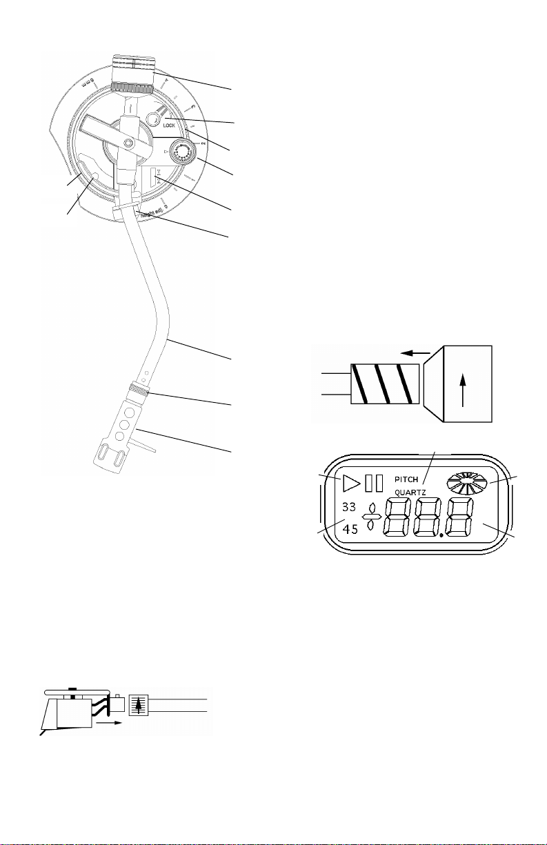
TONE ARM ASSEMBLY
30
33
22
23
18. Headshell- Install cartridge here.
When installing a cartridge, refer to
the installation instructions supplied
by the manufacturer of that
cartridge. During installation, attach
the stylus protector to guard the
stylus tip from damage.
Attach wires as follows:
White (L+)Left channel +
Blue (L-) Left channel
Red (R+) Right channel +
Green (R-)Right channel
19. Headshell Locking Nut - Attach
headshell by inserting into the front
end of the tonearm, then turn the
locking nut clockwise with the head
shell firmly held horizontally.
20. S-Shaped Tone Arm
21. Tone Arm Clamp and Rest - Use this
rest for the tone arm and clamp it in
position during transportation.
22. Tone Arm Lift - This elevates the
tone arm above the record surface.
23. Tone Arm Lift Adjust Screw -
28
27
26
25
24
21
Controls the amount of lift.
24. Tone Arm Lever - Controls the up
and down action of the Tone Arm
Lift.
25. Anti-Skate Control - This applies
inward force to the tonearm so it
doesn’t skip outward across the
record due to the centrifugal force of
the record spinning. Cartridge
manufacturers usually specify the
proper setting of this.
26. Tone Arm Height Adjust - This allows
the tone arm to be properly align
with the platter surface.
27. Height Lock - Prevents accidental
adjustment of the height.
28. Counterweight - Adjustment creates
the proper downward pressure of the
stylus to the record. Attach now by
sliding the counterweight onto the
rear of the tonearm. Twist it lightly
and it will screw onto the rear shaft
of the tonearm.
20
19
LCD DISPLAY
32
18
31
29
29. Speed Indication
33 - 33 rpm
45 - 45 rpm
33 + 45 - 78 rpm
30. Speed Adjust Indication - This will
display adjustments in platter speed
made by the pitch control.
31. Play/Pause - Indicates current state
of the platter
32. Pitch/Quartz - Indicates current
mode of operation
33. Platter Wheel - Simulates all actions
of speed and direction of the platter.
Page 5
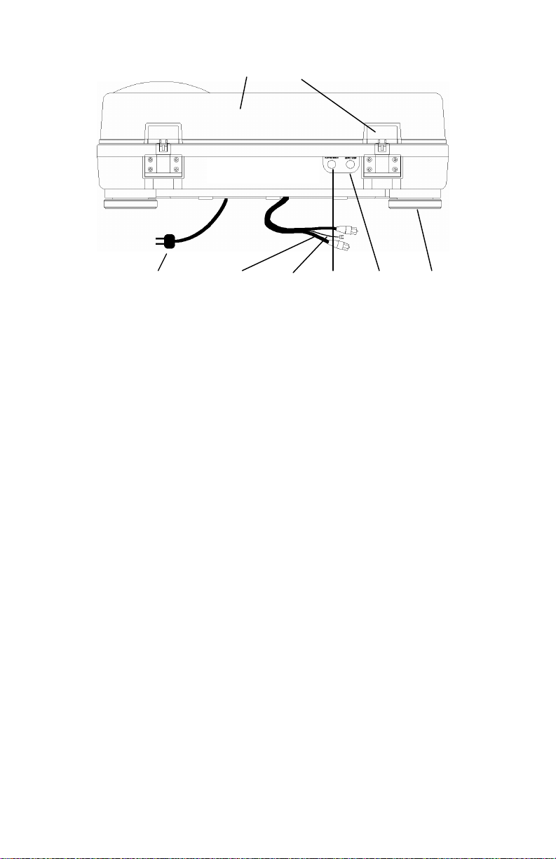
REAR PANEL DIAGRAM
34
35
41
34. Removable Lid - Protects the
turntable from dirt and dust.
35. Hinge Assembly - Holds the lid and
turntable together. Attach now by
sliding the bottom tabs of the Hinge
Assembly into the Hinge Holders.
36. Platter Speed Output - This output is
to be used with external devices that
require platter speed information.
37. Remote Start/Stop - This is used with
external control devices.
Tech note: This circuit is normally
open. Use a momentary switch and
a 1/4” mono plug, to change play
states of the unit.
Your assembly should now be complete. Place your turntable on a vibration free
level surface and attach to your mixer or preamplifier. If you are using the turntable
for slip cueing, scratching, or beat mixing music you will want to use a slipmat and
not a rubber mat. Do not force the platter to stop moving while the motor is
engaged. Quality slipmats should be used to hold records in position. Forcing the
motor to stop can damage the motor assembly.
39
40
37
38. Adjustable Feet - Turn feet to level
the platter surface.
39. Phono Output - Plug these into your
mixer or preamplifiers’ turntable
input.
40. Ground Cable - Attach to the ground
screw on your mixer or preamplifier
to prevent turntable hum.
41. Power Cord - Plug this into an
appropriate power outlet after
checking your power setting switch
(18) under the platter.
36
38
Page 6
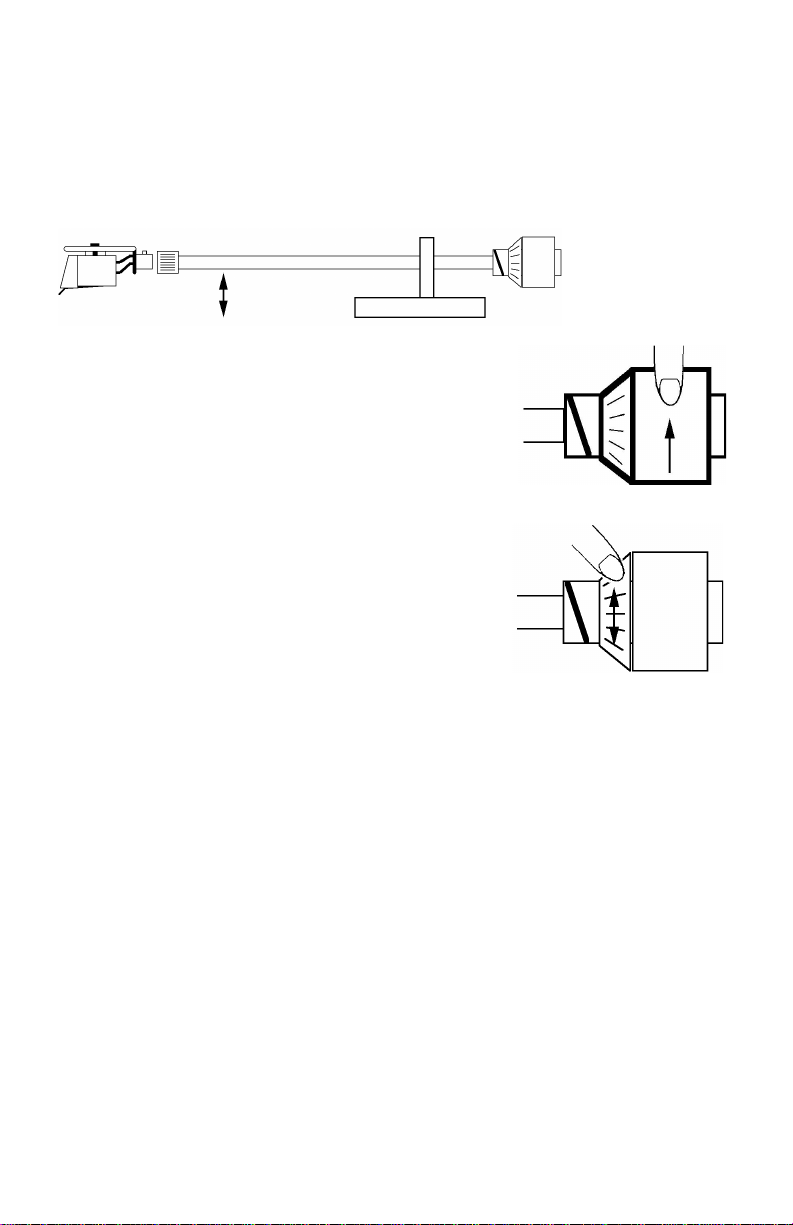
TONE ARM SETTINGS
The following explains proper counterweight and anti-skating set up. Cartridge manufacturers
usually specify the proper settings.
a) Remove the stylus protector, do not touch the stylus tip during the adjustment.
b) Set the cueing lever to the lower position so it does not effect tone arm height.
c) Set Anti-skate adjustment to 0.
d) Place counterweight on the rear of the tone arm
e) Release the arm clamp and lift the tonearm from the arm rest so it moves freely.
f) Rotate the counterweight until the tonearm is approximately balanced horizontally (floats
freely).
g) Refasten the tonearm with the arm clamp.
h) Hold the counterweight stationary with one hand and
rotate only the stylus-pressure ring to bring the number
"O" of the ring into alignment with the center line on the
tonearm rear shaft.
i) Rotate the counterweight with scale ring clockwise to the
correct stylus pressure following the manufacturer's
recommendation.
Note: Failure to follow recommended stylus pressure
could damage both the stylus and record. This can also
seriously degrade performance.
j) Set the anti-skating control knob to the same value as
the stylus pressure, unless your manufacturer specifies
otherwise.
Page 7
GUÍA DE INICIO RÁPIDO PARA EL MEZCLADOR (ESPAÑOL)
TO PHONOTO PHONO
TO LINETO LINE
1. Asegúrese de que todos los artículos incluidos al inicio de este manual están
incluidos en la caja.
2. LEA EL FOLLETO DE INSTRUCCIONES DE SEGURIDAD ANTES DE UTILIZAR EL
PRODUCTO.
3. Estudie este diagrama de instalación.
4. Coloque el producto en una posición adecuada para su funcionamiento.
5. Asegúrese de que todos los dispositivos están apagados y de que todos los faders
están en la posición «cero».
6. Conecte todas las fuentes de entrada al estéreo como se indica en el diagrama.
7. Conecte las salidas del estéreo a los amplificadores de alimentación, unidades de
cinta magnética, y/o fuentes de audio.
8. Enchufe su mezclador y otros dispositivos a la potencia de corriente alterna.
9. Prenda todo en el siguiente orden:
10. Al apagar, realice siempre esta operación al contrario:
11. Visite http://www.ion-audio.com para registrar el producto.
• fuentes de entrada de audio (p.ej. giradiscos o reproductores de CD)
• su mezclador
• por último, cualquier amplificador
• apague los amplificadores
• su mezclador
• por último, cualquier dispositivo de entrada
Page 8
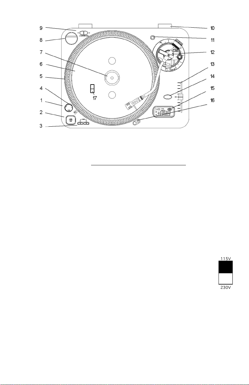
DIAGRAMA Y DESCRIPCIÓN DE LAS PARTES
completo antes de ponerlo en funcionamiento. El ITT03X debería ser colocado en una superficie sólida
y a nivel. Recuerde que puede que existen ciertas características que puede que nunca ha visto antes
en un giradiscos de este tipo y sobre las cuales deberá leer para un funcionamiento adecuado.
cuidado, compruebe todo el material de la caja para localizar las partes no visibles. Fíjese en la guía
de contenidos como referencia. ¡No se deshaga del material de embalaje!
1. Dial de encendido
2. START/STOP – Al pulsarlo una vez se
3. Controles de velocidad para las
4. Luz Estroboscópica – Desprende un rayo
5. Puntos Estroboscópicos – Cuatro filas de
6. Plato – Colóquelo en el eje central.
7. Eje Central – Mantiene el plato y los
8. Adaptador de 45 – Colóquelo en el eje
9. Botones Adelante/Atrás – Determinan la
10. Ranuras para las bisagras de la tapa –
11. Portacápsulas adicional – Coloque aquí
Para poder apreciar todas las características de ITT03X, por favor, lea el manual por
Comience sacando todas las partes de la caja y colocándolas en una superficie a nivel. Con
On – Gire hacia la derecha
Off – Gire hacia la izquierda
activa el motor de tracción directa con
torque alto (high torque); al pulsarlo de
nuevo, se activa el freno.
revoluciones del plato.
33 rpm - Presione 33
45 rpm - Presione 45
78 rpm - Presione 33 y 45
de luz en los puntos Estroboscópicos.
Los puntos grandes parecerán no
moverse cuando el pitch es del 0%.
puntos que indican varias etapas en el
ajuste del pitch.
-3,3% - fila más hacia afuera
0% - puntos grandes
+3,3% - fila siguiente
+6% - fila más hacia adentro
discos centrados. Coloque ahora la
alfombrilla suministrada sobre el eje
central.
central para reproducir discos de 7” con
agujeros centrales anchos.
dirección en la que el plato girará.
Coloque aquí los soportes de sus
bisagras después de terminar el
montaje del giradiscos.
un portacápsulas adicional.
12. Montaje del brazo de lectura– Se explica
en la sección que trata del montaje del
brazo de lectura.
13. Ajuste del pitch – Use esto para cambiar
la velocidad del plato cuando el bloqueo
por cuarzo esté inactivo.
14. Bloqueo por cuarzo
On – mantiene la velocidad de giro al
0%.
Off – permitirá usar el ajuste del pitch.
MANTÉNGALO PULSADO para alternar
entre un pitch del 10% o del 20%.
15. Pantalla LCD (sólo para iTT03X) –
Explicado en la sección de la pantalla.
16. Periscopio de iluminación – Pulse el
botón hacia la derecha y una luz dirigida
hacia la posición de la aguja se
iluminará.
17. Selector de voltaje – Con la
unidad desconectada, ajuste el
voltaje para su país utilizando
un destornillador.
Page 9

MONTAJE DEL BRAZO DE LECTURA
30
33
22
23
21. Soporte de fijación del brazo – Use este
soporte para el brazo y sujételo durante
el transporte del giradiscos.
22. Elevador del brazo de lectura – Esto
28
27
26
25
24
21
20
eleva el brazo sobre la superficie del
disco.
23. Tornillo de ajuste para el elevador del
brazo – Controla la cantidad de
elevación.
24. Palanca del brazo – Sube o baja el
elevador del brazo.
25. Control anti-skate – Aplica una fuerza
de entrada al brazo para que no salte a
través del disco por causa de la fuerza
centrifuga del disco que gira. Los
fabricantes de las cápsulas
normalmente especifican los ajustes
adecuados.
26. Ajuste de la altura del brazo de lectura
(sólo iTT03X) – Esto permite que el
brazo esté alineado correctamente con
la superficie del plato.
27. Bloqueo de altura (sólo iTT03X) – Evita
los ajustes accidentales de la altura del
brazo.
28. Contrapeso – Al ajustarlo se crea la
presión adecuada sobre la aguja y, a su
vez, sobre el disco. Instálelo ahora
deslizando el contrapeso hacia la parte
trasera del brazo. Gírelo ligeramente y
se atornillará en el eje trasero del
brazo.
19
18. Portacápsulas – Instale aquí su cápsula.
Al instalar una cápsula, lea las
instrucciones de instalación facilitadas
por el fabricante de esa cápsula.
Durante la instalación, coloque el
protector de aguja para evitar que se
dañe la punta de la aguja.
Conecte los cables de la siguiente
manera:
Blanco (L+)Canal izquierdo +
Azul (L-) Canal izquierdo
Rojo (R+) Canal derecho +
Verde (R-) Canal derecho
19. Tuerca de fijación del portacápsulas –
Instale el portacápsulas insertándolo en
el extremo frontal del brazo, luego gire
la tuerca de fijación en el sentido de las
agujas del reloj con el portacápsulas
sujetado firmemente en posición
horizontal.
20. Brazo de lectura en forma de «S».
18
PANTALLA LCD
32
31
29
29. Indicador de velocidad
33 - 33 rpm
45 -45 rpm
33 + 45 -78 rpm
30. Indicador de ajuste de velocidad – Esto
mostrará los ajustes en la velocidad del
plato realizados por el control del pitch.
31. Play/Pause – Indica el estado actual del
plato.
32. Pitch/Cuarzo – Indica el modo actual de
operación.
33. Rueda del plato – Simula todas las
funciones de velocidad y dirección del
plato.
Page 10

DIAGRAMA DEL PANEL TRASERO
34
35
41
34. Tapa extraíble – Protege el giradiscos
del polvo y la suciedad.
35. Montaje de bisagras – Sujeta la tapa
al giradiscos. Instálelo ahora
deslizando los soportes del montaje
de bisagras hacia dentro de los
portabisagras.
36. Salida de velocidad del plato – Esta
salida debe ser utilizada con
dispositivos externos que requieran
la información de velocidad del plato.
37. Start/Stop remoto – Se usa con los
dispositivos de control externos.
Nota técnica: Este circuito suele
estar abierto. Use un interruptor
momentáneo y un enchufe mono de
1/4" para cambiar los estados de
reproducción de la unidad.
Ya ha finalizado el montaje de su giradiscos. Coloque su giradiscos sobre una
superficie a nivel libre de vibraciones y conéctelo a su mezclador o pre-amplificador.
Si está usando el giradiscos para pre-escucha, scratching o mezcla de beats, preferirá
usar una alfombrilla y no una base de goma. No intente frenar el plato mientras el
motor esté en marcha. Debería usar alfombrillas de calidad para mantener los discos
en su lugar. Frenar el motor puede dañar el montaje del motor.
39
40
37
38. Pies ajustables – Gire los pies para
nivelar la superficie del plato.
39. Salida phono – Enchúfelos a su
mezclador o a la entrada de los preamplificadores del giradiscos.
40. Toma a tierra – Únalo al tornillo de
tierra de su mezclador o preamplificador para evitar el zumbido.
41. Cable de alimentación – Conéctelo a
una toma de corriente adecuada
después de revisar el interruptor de
nivel de alimentación (18) que se
encuentra debajo del plato.
36
38
Page 11

AJUSTES DEL BRAZO DE LECTURA
La siguiente información explica el contrapeso adecuado y la configuración del control anti-
skating). Los fabricantes de las cápsulas suelen especificar los ajustes adecuados.
a) Retire el protector de la aguja, no toque la punta de la aguja durante el ajuste.
b) Ponga la palanca cue en la posición más baja para que no afecte a la altura del brazo de
lectura.
c) Ponga el ajuste anti-skate a 0.
d) Coloque el contrapeso en la parte trasera del brazo de lectura.
e) Suelte el soporte de fijación del brazo y levante el brazo de lectura de su soporte para que
pueda moverse libremente.
f) Gire el contrapeso hasta que el brazo esté balanceado horizontalmente aproximadamente
(flotando libremente).
g) Fije de nuevo el brazo de lectura con el soporte de fijación.
h) Mantenga el contrapeso quieto con una mano y gire
solamente el anillo de presión de la aguja para alinear el
número «0» del anillo con la línea central del eje trasero
del brazo de lectura.
i) Gire el contrapeso con el anillo numerado en el sentido
de las agujas del reloj para corregir la presión de la
aguja recomendada por el fabricante.
Nota: El incumplimiento en las instrucciones
recomendadas sobre la presión de la aguja podría dañar
la aguja y el disco. Esto puede también podría hacer
que disminuyese el rendimiento de este aparato
considerablemente.
j) Ponga el control de anti-skating al mismo valor que la
presión de la aguja, a menos que su fabricante indique
algo distinto.
Page 12

KURZBEDIENUNGSANLEITUNG (DEUTSCH)
TO PHONOTO PHONO
TO LINETO LINE
1. Überprüfen Sie, daß alle auf der Vorderseite dieser Anleitung aufgeführten
Teile in der Verpackung enthalten sind.
2. LESEN SIE DIE SICHERHEITSHINWEISE VOR INBETRIEBNAHME
DES PRODUKTS
3. Sehen Sie sich dieses Aufbaudiagramm genau an.
4. Stellen Sie das Gerät an einen für den Betrieb geeigneten Platz.
5. Stellen Sie sicher, daß alle Geräte ausgeschaltet sind und alle Fader auf
“null” stehen.
6. Schliessen Sie alle Stereosignalquellen wie im Diagramm gezeigt an.
7. Schliessen Sie die Stereoausgänge an den (die) Verstärker,
Kassettendecks und/oder Tonquellen an.
8. Schliessen Sie Ihr Mischpult und andere Geräte an das Stromnetz an.
9. Schalten Sie alles in der folgenden Reihenfolge ein.
10. Beim Ausschalten drehen Sie diese Reihenfolge um, indem Sie,
11. Besuchen Sie die Webseite http://www.ion-audio.com, um das Produkt zu
· Tonsignalquellen (z.B. Platten- oder CD-Spieler)
· Ihr Mischpult
· zuletzt, vorhandene Verstärker
§ die Verstärker ausschalten
§ dann Ihr Mischpult
§ und zuletzt vorhandene Signalquellen
registrieren.
Page 13

SCHEMATISCHE DARSTELLUNG UND BESCHREIBUNG DER TEILE
vollständig geniessen zu können. Der ITT03X sollte auf eine ebene, widerstandsfähige Oberfläche gestellt
werden. Denken Sie daran, daß einige Eigenschaften vorhanden sind, welche Sie möglicherweise bei einem
Plattenspieler dieses Typs noch nie zuvor gesehen haben und über welche Sie daher informiert sein müssen,
um diese entsprechend benutzen zu können.
Sehen Sie im Verpackungsmaterial genau nach möglicherweise versteckten Teilen nach. Ziehen Sie die
Inhaltsliste als Leitfaden hinzu. Werfen Sie keine Verpackungen weg!
1. Ein/Aus-Drehschalter
2. START/STOP – Einmaliges Drücken aktiviert
3. Tasten für Plattentellergeschwindigkeit
4. Abtastlicht – Wirft einen Lichtstrahl auf die
5. Abtastpunkte – Vier Reihen von Punkten,
6. Plattenteller – Setzen Sie diesen auf die
7. Zentralnabe – sorgt für die Zentrierung des
8. 45-Mittelstück – Setzen Sie deses auf die
9. Vorwärts/Rückwärts-Tasten – bestimmen
10. Halter für Abdeckscharniere – Setzen Sie
11. Halter für Ersatz-Tonabnehmernadel –
12. Zusammenbau des Tonarms – Wird im
Lesen Sie bitte diese ganze Anleitung vor Inbetriebnahme, um die Eigenschaften des ITT03X
Fangen Sie an, indem Sie sämtliche Teile auspacken und diese auf eine ebene Oberfläche legen.
Ein - Rechtsdrehung
Aus - Linksdrehung
den Motor mit hohem Drehmoment;
erneutes Drücken aktiviert die Bremse.
33rpm – 33 drücken
45rpm – 45 drücken
78rpm - 33 und 45 drücken
Abtastpunkte. Die großen Punkte scheinen
sich nicht zu bewegen, wenn die Tonhöhe
auf 0% steht.
welche verschiedene Stufen bei Einstellung
der Tonhöhe andeuten.
-3.3% - äußere Reihe
0% - große Punkte
+3.3% - nächste Reihe
+6% - innere Reihe
Zentralnabe.
Plattentellers und der Schallplatten. Legen
Sie nun die beigelegte Slipmat auf die
Zentralnabe.
Zentralnabe, wenn 7”-Schallplatten mit
großen Mittellöchern abgespielt werden
sollen.
die Drehrichtung des Plattentellers.
die unteren Laschen der Abdeckscharniere
hier ein, nachdem Sie mit dem
Zusammenbau fertig sind.
Setzen Sie ein Ersatz-
Tonabnehmergehäuse hier ein.
Abschnitt Tonarm erklärt
13. Tonhöheneinstellung – Zur Einstellung der
Geschwindigkeit des Plattentellers, wenn
die Quarzsperre nicht aktiviert ist.
14. Quarzsperre
Ein – hält die Umdrehungsgeschwindigkeit
konstant auf 0%
Aus – gestattet die Verwendung der
Tonhöheneinstellung
HERUNTERHALTEN – um zwischen einer
Tonhöhe von 10% bis 20% umzuschalten
15. Flüssigkristallanzeige – Wird in im Abschnitt
Anzeige erklärt
16. Ziellampe – Ein Drücken der rechten Taste
führt zum Herausfahren einer Lampe,
welche auf den Tonkopf gerichtet ist.
17. Spannungswahl – Stellen Sie die
für Ihre Örtlichkeit korrekte
Spannung mit einem
Schraubenzieher ein, während
das Gerät ausgesteckt ist.
Page 14

ZUSAMMENBAU DES TONARMS
30
33
22
23
23. Einstellschraube für Tonarmheber – Dient
zur Einstellung der Hebehöhe.
24. Tonarmhebel – Steuert die Auf- und
28
27
26
25
24
21
Abbewegung des Tonarmhebers.
25. Anti-Skate-Steuerung – Erzeugt einen nach
innen gerichteten Druck auf den Tonarm,
um diesen am Ausbrechen über die Platte
aufgrund der Fliehkraft der sich drehenden
Schallplatte zu hindern. Die Hersteller von
Steckmodulen geben normalerweise die
richtigen Einstellwerte dafür an.
26. Tonarmhöheneinstellung – Hier kann die
Höhe des Tonarms im Verhältnis zur
Oberfläche des Plattentellers eingestellt
werden.
27. Höhensperre – Verhindert eine
unbeabsichtigte Veränderung der Höhe.
28. Gegengewicht –Einstellung desselben führt
zum richtigen Druck der Tonabnehmernadel
auf die Schallplatte. Setzen Sie das
Gewicht auf das hintere Ende des Tonarms.
Mit einer leichten Drehung kann es auf den
hinteren Teil des Tonarms aufgeschraubt
werden.
20
19
18
18. Tonabnehmergehäuse – Setzen Sie das
Steckmodul hier ein. Beachten Sie die
mitgelieferten Anweisungen des Herstellers
des Steckmoduls beim Installieren.
Schützen Sie die Tonabnehmernadel
während des Einbaus, indem Sie die
Schutzkappe auf die Nadel setzen.
Schliessen Sie die Kabel wie folgt an:
Weiß (L+) Linker Kanal +
Blau (L-) Linker Kanal
Rot (R+) Rechter Kanal +
Grün (R-) Rechter Kanal
19. Arretierschraube für Tonabnehmergehäuse
– Setzen Sie das Tonabnehmergehäuse in
das vordere Ende des Tonarms ein und
drehen Sie dann die Arretierschraube im
Uhrzeigersinn, während Sie das Gehäuse
horizontal festhalten.
20. S-förmiger Tonarm
21. Tonarmklemme und -ablage – Legen Sie
den Tonarm auf dieser Ablage ab und
sichern Sie ihn mit der Klemme wenn das
Gerät transportiert wird.
22. Tonarmheber – Hebt den Tonarm über die
Plattenoberfläche.
FLÜSSIGKRISTALLANZEIGE
32
31
29
29. Geschwindigkeitsanzeige
33 - 33 rpm
45 - 45 rpm
33 + 45 - 78 rpm
30. Anzeige Geschwindigkeitseinstellung – Hier
wird angezeigt, welche
Geschwindigkeitseinstellungen am
Plattenteller durch die Tonhöhensteuerung
vorgenommen werden.
31. Abspielen/Pause – Zeigt den momentanen
Betriebsmodus des Plattentellers an
32. Tonhöhe/Quarz – Zeigt den momentanen
Betriebsmodus an
33. Plattenteller-Rad – Simuliert alle Vorgänge
in Bezug auf Geschwindigkeit und
Drehrichtung des Plattentellers.
Page 15

SCHEMATISCHE DARSTELLUNG RÜCKSEITE
34
35
41
34. Abnehmbare Abdeckhaube – Schützt
den Plattenspieler vor Staub und
Verschmutzung.
35. Scharniervorrichtung – Bildet die
Verbindung zwischen Abdeckhaube
und Plattenspieler. Setzen Sie die
Abdeckhaube nun auf, indem Sie die
unteren Laschen der Scharniere in
die dafür vorgesehenen
Scharnierhalterungen einschieben.
36. Ausgang Plattentellergeschwindigkeit
– Dieser dient zur Verwendung mit
externen Geräten, welche
Informationen über die
Geschwindigkeit des Plattentellers
benötigen.
37. Fernbedienung Start/Stop – Kann mit
externen Steuerungsgeräten benutzt
werden.
Technischer Hinweis: Dieser
Schaltkreis ist normalerweise offen.
Um den Abspielmodus des Geräts zu
ändern, verwenden Sie einen
Momentschalter und einen 6,33mm
Mono-Stecker.
Der Zusammenbau sollte nun vollständig erledigt sein. Stellen Sie Ihren
Plattenspieler auf eine ebene, vibrationsfreie Oberfläche und schliessen Sie ihn an
Ihr Mischpult oder Vorverstärker an. Falls Sie Ihren Plattenspieler zum Slip-Cueing,
Scratching oder zum Mischen von Musiktakten benutzen möchten, sollten Sie eine
Slipmat und keine Gummimatte verwenden. Versuchen Sie nicht, den Plattenteller
während des Motorbetriebs gewaltsam anzuhalten. Nur qualitativ gute Slipmats
sollten dazu verwendet werden, die Platten an Ort und Stelle zu halten. Versuche,
den Motor anzuhalten, können die Antriebseinheit beschädigen.
39
40
37
38. Einstellbare Standfüße – Drehen Sie
die Standfüße, um die Oberfläche des
Plattentellers waagerecht zu halten.
39. Phono-Ausgang – Stecken Sie diese
in den Plattenspielereingang Ihres
Mischpults oder Vorverstärkers.
40. Erdungskabel – Schrauben Sie dies
auf die Erdungsschraube Ihres
Mischpults oder Vorverstärkers um
ein Brummen des Plattenspielers zu
vermeiden.
41. Stromkabel – Stecken Sie dies in
eine entsprechende Steckdose,
nachdem Sie den Einstellschalter
(18) unter dem Plattenteller
überprüft haben.
36
38
Page 16

EINSTELLUNGEN DES TONARMS
Nachstehend ist die genaue Einstellung des Gegengewichts und des Anti-Skating erläutert.
Hersteller von Steckmodulen geben normalerweise die richtigen Einstellungen an.
a) Nehmen Sie den Tonnadelschutz ab und berühren Sie die nadelspitze während des
Einstellens nicht.
b) Setzen Sie den Cueing-Hebel auf die niedrige Position, sodaß dieser nicht die Höhe des
Tonarms beeinflusst.
c) Stellen Sie das Anti-Skate auf 0.
d) Setzen Sie das Gegengewicht auf das hintere Ende des Tonarms
e) Öffnen Sie die Halteklemme und heben Sie den Tonarm von der Ablage herunter, sodaß er
frei beweglich ist.
f) Drehen Sie das Gegengewicht, bis der Tonarm nahezu waagerecht balanciert (frei
schwebt).
g) Stellen Sie den Tonarm wieder mit der Halteklemme fest.
h) Halten Sie das Gegengewicht mit einer Hand fest und
drehen Sie nur den Tonnadeldruckring bis die Nummer
"O" des Ringes mit der mittleren Linie des hinteren Ende
des Tonarms in einer Linie steht.
i) Drehen Sie das Gegengewicht mit dem Skalenring im
Uhrzeigersinn bis zum vom Hersteller empfohlenen
Abtastnadeldruck.
Hinweis: Falls der empfohlene Abtastnadeldruck nicht
eingestellt wird, kann dies zu Beschädigung der Nadel
als auch der Schallplatte führen. Es kann auch eine Ursache für verminderte
Leistungsfähigkeit sein.
j) Stellen Sie den Anti-Skate Kontrollregler auf denselben
Wert wie den Abtastnadeldruck, es sei denn, Ihr
Hersteller empfiehlt andersweitig.
Page 17

GUIDE D’INSTALLATION RAPIDE (FRANÇAIS)
TO PHONOTO PHONO
TO LINETO LINE
1. Assurez-vous que tous les articles énumérés sur la page couverture de ce guide sont
inclus dans la boîte.
2. LIRE LE LIVRET DES CONSIGNES DE SÉCURITÉ AVANT D’UTILISER LE
PRODUIT
3. Examinez bien le schéma d’installation.
4. Placez l’appareil en position de fonctionnement.
5. Assurez-vous que tous les appareils sont hors tension et que tous les atténuateurs et
sont réglés à « zéro ».
6. Connectez toutes les sources d’entrées stéréo tel qu’indiqué sur le schéma.
7. Brancher toutes les sorties stéréo aux amplificateurs de puissance, aux lecteurs de
cassette et/ou aux sources audio.
8. Branchez la console de mixage et autres appareils à une prise à alimentation CA.
9. Mettre tous les appareils sous tension dans l’ordre suivant :
· sources d’entrée audio (i.e. tourne-disque ou lecteurs de disques
compacts)
· La console de mixage
10. Pour mettre hors tension, toujours inverser l’opération :
11. Allez à http://www.ion-audio.com pour enregistrer le produit.
· En dernier, tous les amplificateurs
§ Éteindre les amplificateurs
§ La console de mixage
§ En dernier, tous les appareils d’entrée
Page 18

SCHÉMA ET DESCRIPTION DES PIÈCES
Pour pouvoir apprécier toutes les fonctions du ITT03X, veuillez lire ce guide en entier
avant de faire fonctionner l’appareil. Le ITT03X doit être placé sur une surface solide, plate et
au niveau. Veuillez prendre note qu’il peut avoir quelques fonctions que vous n’ayez jamais
vues auparavant sur un tourne-disque de ce type et vous devrez lire l’information contenue
dans ce guide pour pouvoir les utiliser correctement.
Retirez toutes les pièces de l’emballage et placez-les sur une surface plate au niveau.
Vérifiez que le matériel d’emballage ne contient aucune pièce dissimulée. Référez-vous à la
liste de contrôle des pièces. Ne jetez pas le matériel d’emballage!
1. Bouton d’alimentation
2. COMMUTATEUR MARCHE/ARRÊT Enfoncez
3. Sélecteur de vitesse du plateau
4. Lumière stroboscopique - Émets un
5. Points stroboscopiques - Quatre rangées de
6. Plateau - Placez le plateau du tourne-
7. Axe central - Permet de maintenir le
8. Adaptateur 45 rpm - À placer sur l’axe
Sous tension – Tournez vers la droite
Hors tension – Tournez vers la
gauche
pour faire démarrer le moteur à couple et
enfoncez à nouveau pour activer le
freinage.
33rpm - Appuyez sur 33
45rpm - Appuyez sur 45
78rpm - Appuyez sur 33 et 45
faisceau lumineux sur les points
stroboscopiques. La rangée inférieure de
points (gros points) semble stationnaire
lorsque la vitesse est à 0 %.
points indiquent les différentes vitesses de
lecture.
-3.3 % - Rangée extérieure
0 % - Gros points
+3.3 % - Rangée suivante
+6 % - Rangée intérieure
disque sur l’axe central.
plateau et les disques centrés. Placez le
tapis fourni sur l’axe central tourne-disque.
central pour faire la lecture de disques de 7
po avec trou au centre.
9. Boutons marche avant/arrière - Détermine
la direction de rotation du plateau.
10. Porte-charnières - Affixez en insérant les
pattes de l’assemblage à charnières dans la
fixation du couvercle lorsque le montage
est terminé.
11. Support de pointe de lecture de rechange. -
Placez une coquille de rechange ici.
12. Montage du bras de lecture - Expliqué plus
en détail dans la section « Bras de
lecture ».
13. Régulateur de vitesse - Permet à
l’utilisateur de modifier la vitesse du
plateau lorsque le verrouillage quartz est
inactivé.
14. Verrouillage Quartz
Activé (On) – maintient la vitesse de
révolution du plateau à 0 %.
Désactivé (Off) – permet de modifier la
vitesse du plateau.
ENFONCÉ - permet d’alterner entre une
vitesse de 10 % et 20 %.
15. Écran à cristaux liquides (ACL) Expliqué
plus en détail dans la section « Écran »
16. Lumière cible - Appuyez sur le bouton de
droite pour faire apparaître une lumière
pour éclairer la pointe de lecture.
17. Sélecteur de tension - Avant de brancher
l’appareil, réglez adéquatement la tension
pour votre région avec l’aide d’un
tournevis.
Page 19

MONTAGE DU BRAS DE LECTURE
30
33
22
23
place le bras de lecture et le serre-bras
lorsque vous transportez l’appareil.
22. Levier de commande du bras de lecture -
Permet de soulever le bras de lecture au-
28
27
26
25
24
21
dessus du disque.
23. Vis de réglage du levier de commande du
bras de lecture - Contrôle la hauteur du
levier de commande.
24. Levier de commande du bras de lecture -
Contrôle le movement de bas en haut du
bras de lecture.
25. Commande anti-dérapage - Permet de
régler le niveau de force d’appui exercé sur
le bras de lecture pour éviter qu’il soit
emporté par la force centrifuge du plateau.
Les fabricants de cartouche spécifient
habituellement le réglage adéquat sur
l’emballage de la cartouche.
26. Hauteur du bras de lecture : Réglage -
Permet d’aligner correctement le bras de
lecture à la surface du plateau.
27. Verrouillage de la hauteur - Permet d’éviter
les déréglages accidentels de la hauteur du
bras de lecture.
28. Contrepoids - L’ajustement permet de
régler la pression de la pointe de lecture
sur le disque. Glissez le contrepoids sur
l’extrémité arrière du bras de lecture.
Tournez-le légèrement pour le visser sur
l’arbre arrière du bras de lecture.
20
19
ÉCRAN À CRISTAUX LIQUIDES (LCD)
18
32
18. Coquille - Installez la cartouche à cet
endroit. Pour installer une cartouche,
veillez vous référer aux instructions
fournies avec la cartouche. Avant
l’installation de la cartouche, veillez fixer le
protège-pointe sur la pointe de lecture afin
d’éviter de l’endommager.
Branchez les conducteurs de la façon
suivante :
Blanc (L+) canal gauche +
Bleu (L-) canal gauche
Rouge (R+) canal droit +
Vert (R-) canal droit
19. Écrou de blocage de la coquille - Insérez la
coquille sur le devant du bras de lecture.
Tout en la tenant fermement dans la
position horizontale, tournez l’écrou de
blocage dans le sens contraire d’une
montre.
20. Bras de lecture en forme de S
21. Serre-bras et porte-bras du bras de lecture
- Utilisez le porte-bras pour maintenir en
31
29
29. Indicateur de vitesse
33 - 33 rpm
45 - 45 rpm
33 + 45 - 78 rpm
30. Indicateur du réglage de vitesse Indique les
modifications du réglage de vitesse
effectuées par le régulateur de vitesse.
31. MODE LECTURE/PAUSE (PLAY/PAUSE)
Indique en quel mode est le plateau.
32. Vitesse de lecture/Verrouillage Quartz
(Pitch/Quartz) - Indique en quel mode est
réglée la vitesse de rotation du plateau.
33. Roue du plateau Simule la vitesse et la
direction de rotation du plateau.
Page 20

SCHÉMA DU PANNEAU ARRIÈRE
34. Couvercle anti-poussière amovible –
Protège le tourne-disque de la poussière.
35. Fixation à charnières - Permet de fixer le
couvercle au tourne-disque. Affixez en
insérant les pattes de l’assemblage à
charnières dans la fixation du couvercle.
36. Sortie vitesse du plateau - Cette sortie peut
être utilisée par des appareils nécessitants
des données concernant la vitesse de
rotation du plateau.
37. Commutateur à distance MARCHE/ARRÊT
Cette sortie peut être utilisée par des
dispositifs de commande externe.
38. Note technique :Ce circuit est normalement
ouvert.Utilisez un bouton-poussoir à rappel
momentané et une prise mono de ¼ po
pour alterner entre les modes de l’appareil.
Le montage du tourne-disque devrait être complété. Placez le tourne-disque sur une surface au
niveau et libre de toutes vibrations, puis fixez à une console de mixage ou un préamplificateur.
Pour utiliser les techniques de calage (slip cueing), de scratch ou de mixage, il faut que vous
utilisiez un tapis en feutrine plutôt que celui en caoutchouc. Ne pas forcer l’arrêt du plateau
lorsque le moteur est activé. Des tapis de qualité doivent être utilisés pour maintenir les disques
en position. Forcer l’arrêt du plateau lorsque le moteur est activé peut endommager le groupe
moteur.
RÉGLAGE DU BRAS DE LECTURE
La section suivante explique comment faire correctement le réglage du contrepoids et de la commande antidérapage. Les fabricants de cartouche spécifient habituellement le réglage approprié sur l’emballage de la
cartouche.
a) Retirez le protège-pointe, tout en prenant soin de ne pas toucher à la pointe de lecture durant le réglage.
b) Réglez le levier de commande à la position la plus basse pour qu’il n’affecte pas la hauteur du bras de
lecture. Réglez la commande anti-dérapage à 0.
d) Glissez le contrepoids sur l’extrémité arrière du bras de lecture
e) Dégagez le bras de lecture du serre-bras et levez-le du porte-bras de façon à ce qu’il bouge librement.
f) Tournez le contrepoids jusqu’à ce que le bras de lecture soit équilibré horizontalement (flotte librement).
Pieds ajustables - Tournez les pieds pour
mettre le plateau au niveau.
39. Sorties Phono - Branchez ces sorties aux
entrées d’une console de mixage ou d’un
préamplificateur.
40. Câble de mise à la terre - Fixez ce câble à
la borne de mise à la terre de votre console
de mixage ou de votre préamplificateur
pour éviter le ronflement.
41. Câble d’alimentation - Branchez ce câble
dans une prise adéquate après avoir vérifié
le sélecteur de tension (17) situé sous le
plateau.
g) Replacez le bras de lecture sur le serre-bras et verrouillez.
h) Stabilisez le contrepoids à l’aide d’une main tout en tournant l’anneau de pression de la pointe de lecture
jusqu’à ce que le numéro « 0 » sur l’anneau s’aligne avec la ligne médiane sur l’arbre arrière du bras de
lecture.
i) Tournez le contrepoids avec l’anneau de pression dans le sens des
aiguilles d’une montre jusqu’à ce que la quantité de pression
recommandée par le fabricant soit atteinte.
Note : Le non-respect des recommandations pour le réglage de la
pression de la pointe pourrait occasionner des dommages à la
pointe de lecture ainsi qu’au disque. Ceci peut également affecter la
performance.
j) Ajustez la commande anti-dérapage à la même valeur que celle de
la pointe de lecture, sauf avis contraire du fabricant.
Page 21

MANUALE RAPIDO DI MONTAGGIO (ITALIANO)
TO PHONOTO PHONO
TO LINETO LINE
1. Verificate che tutti gli elementi elencati sul frontespizio di questo manuale siano inclusi nella
confezione.
2. PRIMA DI UTILIZZARE IL PRODOTTO LEGGETE IL LIBRETTO DELLE ISTRUZIONI
DI SICUREZZA
3. Esaminate attentamente lo schema di montaggio.
4. Posizionate il prodotto in modo adeguato all’operazione.
5. Assicuratevi che tutti i dispositivi siano spenti e che i fader siano a “zero”
6. Collegate tutte le sorgenti d’ingresso stereo come indicato nello schema.
7. Collegate le uscite stereo agli amplificatori, alle piastre di registrazione e/o a sorgenti audio.
8. Collegate il mixer e gli altri dispositivi alla corrente c.a.
9. Accendete tutto nel seguente ordine:
10. Al momento dello spegnimento, invertite sempre questa operazione:
11. Andate sul sito http://www.ion-audio.com per la registrazione del prodotto.
· sorgenti d’ingresso audio (cioè i giradischi o i lettori CD)
· il mixer
· per ultimi, tutti gli amplificatori
§ spegnendo gli amplificatori
§ il mixer
§ per ultimi, tutti i dispositivi di ingresso
Page 22

SCHEMA E DESCRIZIONE DEGLI ELEMENTI
Per apprezzare appieno le funzioni del ITT03X, prima di iniziare ad usarlo, leggere
l'intero manuale. Il ITT03X deve essere posto su una superficie piana e robusta. Ricordate che
vi sono alcune funzioni che potreste non aver mai visto su un giradischi di questo tipo, e di cui
dovrete leggere per poterle usare adeguatamente.
Iniziare estraendo tutti gli elementi dall'imballaggio e disponendoli su un ripiano.
Controllare attentamente tutti gli imballaggi per trovare eventuali elementi nascosti. Fare
riferimento alla guida ai contenuti. Non gettare i materiali d'imballaggio!
1. Accensione
2. START/STOP - Premendo una volta si
3. Tasti Velocità di Rotazione del Disco
4. Luce Stroboscopica - Fa pulsare un raggio
5. Puntini Stroboscopici - Quattro linee di
6. Piatto - Va posto sull'asse centrale.
7. Asse Centrale - Mantiene il piatto e i dischi
8. Adattatore 45 giri - Posizionatelo sull'asse
9. Tasti Avanti (Forward)/Indietro (Reverse) -
10. Sostegni per Copertura Antipolvere - Dopo
11. Supporto per Puntina Supplementare -
On (acceso) - Girare a destra
Off (spento) - Girare a sinistra
innesta il motore ad alta coppia;
un'ulteriore pressione provoca la frenata.
33 giri - Premere 33
45 giri - Premere 45
78 giri - Premere 33 e 45
di luce lungo i puntini stroboscopici.
Quando il pitch è allo 0% sembrerà che i
puntini grandi non si muovano.
puntini che indicano vari livelli di
regolazione del pitch.
-3.3% - linea esterna
0% - puntini grandi
+3.3% - linea successiva
+6% - linea interna
centrati. Adesso posizionate sull'asse
centrale il tappetino slipmat in dotazione.
centrale per suonare dischi a 7" con un foro
centrale grande.
Determinano il verso di rotazione del
piatto.
aver terminato l'assemblaggio, posizionate
a questo livello la parte inferiore dei vostri
perni.
Posizionate qui un fonorivelatore
supplementare.
12. Complesso del Braccio - Spiegato nel
paragrafo relativo al braccio.
13. Regolazione del Pitch - Utilizzatela per
cambiare la velocità del piatto quando il
quartz lock è inattivo.
14. Quartz Lock
Acceso (on) - manterrà la velocità di
rotazione a 0%
Spento (off) - Permetterà l'uso della
regolazione del pitch
HOLD DOWN - alterna la regolazione del
pitch in una gamma dal 10% al 20%
15. Display LCD - Descritto nel paragrafo
relativo al display
16. Luce Bersaglio - Premete il tasto a destra e
uscirà una luce diretta alla posizione della
puntina.
17. Selettore di Voltaggio - A unità
scollegata, impostate il voltaggio
corretto per la vostra zona di
residenza utilizzando un
cacciavite.
Page 23

COMPLESSO DEL BRACCIO
30
33
22
23
20. Braccio a S
21. Fermabraccio e Portabraccio - Posizionare il
braccio sul portabraccio e bloccarlo in
posizione con il fermabraccio durante il
28
27
26
25
24
21
trasporto.
22. Alzabraccio - Alza il braccio dalla superficie
del disco.
23. Vite di Regolazione dell'Alzabraccio -
Controlla la quantità di alzata.
24. Leva del braccio - Controlla l'azione di
sollevamento e abbassamento
dell'alzabraccio.
25. Dispositivo Anti-Skating - Applica al braccio
una forza verso l'interno impedendogli di
saltare a causa della forza centrifuga del
disco. I produttori di cartucce solitamente
ne specificano la corretta impostazione.
26. Regolazione dell'Altezza del Braccio -
Permette al braccio di essere allineato
correttamente con la superficie del piatto
portadischi.
27. Blocco dell'Altezza - Previene modifiche
accidentali dell'altezza.
28. Contrappeso - La sua regolazione permette
la corretta pressione della puntina sul
disco. Inserite ora il contrappeso facendolo
scivolare sulla parte posteriore del braccio.
Giratelo leggermente e si avviterà sull'asta
posteriore del braccio.
20
19
18
18. Fonorivelatore - Inserite la cartuccia a
questo livello. Quando installate una
cartuccia, fate riferimento alle istruzioni
d'installazione fornite dal produttore di
quella cartuccia. Durante l'installazione,
inserite il copri-puntina, per evitare che la
punta venga danneggiata.
Collegate i fili come segue:
Bianco (L+) Canale sinistro +
Blu (L-) Canale sinistro
Rosso (R+) Canale destro +
Verde (R-) Canale destro
19. Controdado del Fonorivelatore - Collegate il
fonorivelatore inserendolo nella parte
anteriore del braccio, quindi girate il
controdado in senso orario tenendo
saldamente il fonorivelatore in posizione
orizzontale.
DISPLAY LCD
32
31
29
29. Indicatore di Velocità
33 - 33 giri
45 - 45 giri
33 + 45 - 78 giri
30. Indicatore Regolazione Velocità -
Visualizzerà le regolazioni della velocità del
piatto portadischi effettuate dal comando
del pitch.
31. Play/Pause - Indica lo stato attuale del
piatto.
32. Pitch/Quartz - Indica lo stato attuale di
funzionamento.
33. Rotella del Piatto - Simula tutte le azioni di
velocità e direzione del piatto.
Page 24

SCHEMA PANNELLO POSTERIORE
41
34. Copertura Rimuovibile - Protegge il
giradischi dalla sporcizia e dalla polvere.
35. Complesso dei Perni - Unisce la copertura
al giradischi. Attaccatelo ora facendo
scivolare la parte inferiore del complesso
dei perni nei rispettivi sostegni.
36. Uscita Velocità del Piatto - Questa uscita
deve essere utilizzata con dispositivi esterni
che richiedono informazioni sulla velocità
del piatto portadischi.
37. Start/Stop Remoto - Questo viene
utilizzato con dispositivi di controllo
esterno.
Nota tecnica: questo circuito normalmente
è aperto. Utilizzate un interruttore
temporaneo ed una presa mono a 1/4" per
Le vostre operazioni di assemblaggio dovrebbero ora essere terminate. Posizionate il vostro giradischi su una
superficie piana e priva di vibrazioni e collegate il mixer o il preamplificatore. Se utilizzate il giradischi per fare
slip cueing, scratchare, o missare musica beat preferirete usare uno slipmat e non un tappetino di gomma.
Non forzate il piatto a fermarsi quando il motore è innestato. Per mantenere i dischi in posizione devono
essere usati slipmat di qualità. Forzare il motore all'arresto può danneggiare il gruppo motore.
IMPOSTAZIONI DEL BRACCIO
Quanto segue spiega l'impostazione corretta del contrappeso e del dispositivo anti-skating. I produttori di
cartucce solitamente specificano le impostazioni corrette.
a) Rimuovete la protezione della puntina, prestando attenzione a non toccarne la punta durante la
regolazione.
b) Impostate la levetta del cueing nella posizione più bassa, in modo tale che non incida sull’altezza del
braccio.
c) Impostate la regolazione del dispositivo anti-skating a 0.
d) Posizionate il contrappeso sulla parte posteriore del braccio.
e) Rilasciate il fermabraccio e fate alzare il braccio dal portabraccio, in modo che si muova liberamente.
f) Ruotate il contrappeso finché il braccio sia approssimativamente bilanciato in posizione orizzontale
("fluttua" liberamente).
39
34
35
36
37
40
cambiare gli stati di riproduzione
dell'apparecchio.
38. Piedini Regolabili - Girate i piedini per
livellare la superficie del piatto portadischi.
39. Uscita Phono - Inseritela nel vostro mixer o
all'ingresso dei preamplificatori del
giradischi.
40. Cavo per la Messa a Terra - Attaccatelo alla
vite di terra sul vostro mixer o
preamplificatore per prevenire ronzii del
giradischi.
41. Cavo di Alimentazione - Collegatelo ad una
presa di corrente adeguata, dopo aver
verificato l'interruttore per l'impostazione
dell'alimentazione (17) situato sotto al
piatto portadischi.
38
g) Fissate nuovamente il braccio con il fermabraccio.
h) Tenete saldamente il contrappeso con una mano, e ruotate solo
l'anello di pressione della puntina fino ad allineare il numero "0" posto
sull'anello con la linea centrale dell'asta posteriore del braccio.
i) Ruotate il contrappeso con l'anello graduato in senso orario fino alla
corretta pressione della puntina, secondo le istruzioni del produttore.
Attenzione: se non viene seguita la pressione consigliata per la
puntina si potrebbero danneggiare sia la puntina che il disco.
Questo può anche influire negativamente sulla qualità delle
prestazioni.
j) Impostate la manopola del controllo anti-skating allo stesso valore
di pressione della puntina, a meno che il vostro produttore non
specifichi altrimenti.
 Loading...