

Page 1

Unrivalled Detection. www.ionscience.com
Hydrosteel 7000
Instrument User Manual V3.1
Part number: 910228
Page 2

Register your instrument online for extended warranty
Thank you for purchasing your Ion Science instrument.
The standard warranty of your instrument can be extended to up to five years
on PhoCheck Tiger and two years on other Ion Science instruments.
To receive your extended warranty, you must register your instrument online
within one month of purchase (terms and conditions apply.)
Visit www.ionscience.com/instrument-registration
Part number: 910228
Page 3

Hydrosteel 7000 MANUAL Ion Science Ltd
Unrivalled Detection. www.ionscience.com
Declaration of conformity
Manufacturer: Ion Science Ltd, The Way, Fowlmere, Cambridge, SG8 7UJ, UK
Product: Hydrosteel 7000
Product Description: a fixed continuous monitor for the measurement of Hydrogen flux through steel
equipment. The flux is used as indication of internal corrosion. Hydrosteel 7000 is
for use in Oil and Gas operations where H2S, HF-acid, or high temperature corrosion
are present. With a 4-20 mA analogue output Hydrosteel 7000 can be simply
integrated into a DCS control system to give warning or control of high corrosion
levels in the operating equipment.
Directive 94/9/EC ATEX
Identification: II 2G Ex ia IIC T4 (-40
o
C ≤ Ta ≤ +60
o
C)
Notified Body: Baseefa Ltd, 1180, Buxton, UK
EC Type Examination Certificate(s)
Baseefa04ATEX0205 latest supplement Baseefa04ATEX0205 issue 4 issued 13
th
February 2009
Standards
BS EN 60079-0:2006 Electrical Apparatus for Potentially Explosive Atmospheres – General Requirement
BS EN 60079-11:2007 Explosive Atmospheres - Equipment Protection by Intrinsic Safety ‘i’
BS EN 61010-1:2010 Safety requirements for electrical equipment for measurement, control and
laboratory use – General requirements
Directive 2004/108EC Electrical Equipment – Electromagnetic Compatibility (EMC)
BS EN 61326:1997 (+A1/A2) Electromagnetic Compatibility (EMC) Equipment for measurement,
control and laboratory use
CFR 47: 2004 Class B EMC – US standard
Clarifications of EMC performance to standards: With respect to BS EN 61326:1997 (+A1/A2) the
Hydrosteel 7000 achieves performance criteria B (that is the apparatus continues to perform after the
test but during the test a degradation of performance is seen).
Other Standards
BS EN ISO 9001:2008 Quality Management Systems – Requirements
BS EN 13980:2002 Potentially Explosive Atmospheres – Application of Quality Systems
On behalf of Ion Science Ltd, I declare that, on the date this product accompanied by this declaration is
placed on the market, the product conforms to all technical and regulatory requirements of the above listed
directives.
Name: Mark Stockdale Position: Technical Director
Signature: Date: 20th November 2008
Page 3 of 43
Page 4

Hydrosteel 7000 MANUAL Ion Science Ltd
Unrivalled Detection. www.ionscience.com
Contents
Declaration of conformity ............................................................................................................................... 3
Statements ....................................................................................................................................................... 5
Responsibility for Use .................................................................................................................................... 5
Warnings ........................................................................................................................................................ 5
Quality Assurance .......................................................................................................................................... 5
Calibration Facility .......................................................................................................................................... 5
Legal Notice ................................................................................................................................................... 5
Packing list ....................................................................................................................................................... 5
Introduction to Hydrosteel 7000 ..................................................................................................................... 7
Introduction to safety certification .............................................................................................................. 10
Installation ...................................................................................................................................................... 11
HY7K probe site identification ...................................................................................................................... 11
HY7K analyser site identification ................................................................................................................. 11
Power and signal requirements ................................................................................................................... 12
Cable Requirements .................................................................................................................................... 14
Removal of cladding and insulation ............................................................................................................. 14
Preparation of test site ................................................................................................................................. 14
HY7K probe installation................................................................................................................................ 15
Thermocouple installation ............................................................................................................................ 18
Re-insulation and cladding ........................................................................................................................... 18
Installation of sample conduit ....................................................................................................................... 20
Mounting of Hydrosteel 7000 analyser ........................................................................................................ 23
Commossioning ............................................................................................................................................. 24
Inspection of the equipment installation ....................................................................................................... 24
Probe connection to Hydrosteel 7000 .......................................................................................................... 25
Terminating power and 4-20mA cable to Hydrosteel 7000 .......................................................................... 28
Start up ......................................................................................................................................................... 30
Operation test ............................................................................................................................................... 30
Hand over ..................................................................................................................................................... 31
Hydrosteel setup ............................................................................................................................................ 32
Clock time .................................................................................................................................................... 32
Flux 4-20mA output range ........................................................................................................................... 32
Operation ..................................................................................................................................................... 32
Hydrosteel 7000 PC software ....................................................................................................................... 33
Installation of Hydrosteel Software .............................................................................................................. 33
Connecting to the Hydrosteel 7000 .............................................................................................................. 33
Downloading data ........................................................................................................................................ 34
Graph operation ........................................................................................................................................... 34
Data table operation ..................................................................................................................................... 35
Data handling ............................................................................................................................................... 35
Print options ................................................................................................................................................. 36
Instrument Settings ...................................................................................................................................... 36
Maintenance and calibration ........................................................................................................................ 37
Hydrosteel 7000 unit maintenance .............................................................................................................. 37
Probe installation .......................................................................................................................................... 37
Fault finding and diagnostics ................................................................................................................ 38
Fault findings ................................................................................................................................................ 38
Diagnostics ................................................................................................................................................... 39
Technical specifications ............................................................................................................................... 40
Instrument warranty and service ................................................................................................................. 42
Warranty ....................................................................................................................................................... 42
Service ......................................................................................................................................................... 42
Contact details ............................................................................................................................................. 42
Manual log ...................................................................................................................................................... 43
Page 4 of 43
Page 5

Hydrosteel 7000 MANUAL Ion Science Ltd
Unrivalled Detection. www.ionscience.com
Statements
Responsibility for Use
Hydrosteel 7000 flux monitor for permanent installation provides flux readings that are subject to
interpretation. Ion Science Ltd can accept no responsibility for the incorrect use that may causes harm or
damage to persons or property.
Inadequate performance of the gas detection equipment described in this manual may not necessarily be
self-evident and consequently equipment must be regularly inspected and maintained. Ion Science
recommends that personnel responsible for equipment use institute a regime of regular checks to ensure it
performs within calibration limits, and that a record be maintained which logs calibration check data. The
equipment should be used in accordance with this manual, and in compliance with local safety standards.
Warnings
1. Please read and understand this User Manual fully before installing operating or servicing the
Hydrosteel.
2. Ensure you are in a SAFE area before carrying out any type of maintenance on the Hydrosteel 7000
Instrument.
3. Substitution of components may impair intrinsic safety and result in unsafe conditions.
4. For safety reasons, the Hydrosteel must only be operated and serviced by qualified personnel.
5. Refer to the certificate for clarification of any aspects of intrinsic safety or contact Ion Science Ltd or
your local Ion Science Ltd representative.
Quality Assurance
Hydrosteel 7000 has been manufactured in compliance with ISO9001:2008 and BSEN 13980:2002, which
ensures that the equipment supplied to our customers, has been designed and assembled reproducibly, and
from traceable components.
Disposal
Dispose of Hydrosteel 7000, its components in accordance with all local and national safety and
environmental requirements. This includes the European WEEE (Waste Electrical and Electronic Equipment)
directive. Ion Science Ltd offers a take back service. Please contact us for more information.
Calibration Facility
Ion Science Ltd offer a calibration service including the issue of certification using equipment which are
themselves traceable to UK national standards.
Legal Notice
Whilst every attempt is made to ensure the accuracy of the information contained in this manual, Ion Science
accepts no liability for errors or omissions, or any consequences deriving from the use of information
contained herein. It is provided "as is" and without any representation, term, condition or warranty of any
kind, either express or implied. To the extent permitted by law, Ion Science shall not be liable to any person
or entity for any loss or damage which may arise from the use of this manual. We reserve the right at any
time and without any notice to remove, amend or vary any of the content which appears herein.
Packing list
Page 5 of 43
Page 6

Hydrosteel 7000 MANUAL Ion Science Ltd
Unrivalled Detection. www.ionscience.com
Please take a little time to check the contents in the Hydrosteel shipment before installation.
Item Description Qty.
1 Hydrosteel 7000 monitor 1
2 This Manual 1
3 Applications Manual 1
4 Software CD 1
5 Modem cable 1
6 USB to RS232 adapter 1
7 HY7K conduit kit consisting of:
7.1 Sample tube assembly 1
7.2 Han connector assembly 1
7.3 P clips for sample tube conduit 6
7.4 Thermocouple junction box 1
8 HY7K probe kit
8.1 AT-S collector plate 1
8.2 Background probe 1
8.3 Magnetically attachable TC cable 2
8.4 Wire brush 1
Accessories include:
1 Banding kit consisting of:
1.1 Banding tool 1
1.2 Banding (3/8”) stainless steel (box 30.5m) 1
1.3 Buckles box of 100 1
2 Magnetic probe fixing kit (4 high temp magnets) 1
Page 6 of 43
Page 7

Hydrosteel 7000 MANUAL Ion Science Ltd
Unrivalled Detection. www.ionscience.com
Introduction to Hydrosteel 7000
The Hydrosteel 7000 is an intrinsically safe instrument for the measurement of hydrogen flux from pipes and
vessels. The unit is designed for operator free maintenance for up to one year, subject to correct installation,
and appropriate power supply. During this time the unit will take unlimited measurements and log them
internally. The unit has two 4-20 mA outputs that provide constant output of flux and surface temperature
data. An RS232 port enables the download of internally stored data. The unit has been robustly designed
with IP66 weather proofing for external installation in most environments.
Hydrosteel 7000 has been designed with a view to presenting trouble free installation, commissioning and
maintenance. For maintenance we recommend the service exchange of the product. Disconnection of the
unit for service can be carried out while the instrument is powered, by simple detachment of analyser
connections, under intrinsically safe conditions.
The requirements for installation in Zone 1 hazardous area are summarised below and in the Installation
summary diagram. The reader should refer to Installation section, and to the Hydrosteel 7000 ATEX
certificate for further details.
Power to instrument should be supplied via zener safety barrier or galvanic isolator.
Two 4-20 mA receivers that supply loop power to hazardous area through appropriate safety barrier /
galvanic isolator are needed.
To ensure EMC compliance always use screened cables for bother power and 4-20 mA outputs.
Mounting to wall or frame with appropriate hole centres.
Probe to be installed on equipment with sample tube connection made to Hydrosteel 7000. Unit must
be within 10 m (32 ft) of probe test point.
Weather protection for probe. It is recommended that the probe is insulated and clad professionally.
The Hydrosteel 7000 has been certified intrinsically safe by European notified body BASEEFA 2001 to the
ATEX directive 94/9/EC. Baseefa04ATEX0205.
Page 7 of 43
Page 8

Hydrosteel 7000 MANUAL Ion Science Ltd
Unrivalled Detection. www.ionscience.com
Introduction to Hydrosteel 7000
Page 8 of 43
Page 9
Hydrosteel 7000 MANUAL Ion Science Ltd
Unrivalled Detection. www.ionscience.com
Time
Operation
0 to 3 minutes
Hydrogen zero measurement
3 to 6 minutes
Hydrogen background reading
6 to 9 minutes
Hydrogen flux reading
9 to 9.5 minutes
Hydrogen sensor diagnostics
9.5 to 10 minutes
Data stored in memory & 4-20mA outputs updated
Introduction to Hydrosteel 7000
Operation Cycle
Hydrosteel 7000 operates a 10 minute measurement cycle. At the end of each cycle, 4-20 mA outputs step
change to provide the most recent cycle data measurement, and store all data and diagnostic measurements
to the internal memory. The unit draws a controlled flow of sample gas from the probe into the unit, where
the concentration of hydrogen gas in the sample is measured. The instrument sequentially measures
hydrogen in sample gas drawn from the background probe (~3 minutes) and flux probe (~3 minutes). From
the differential response, the flux is calculated and data outputs are updated. The rest of the cycle (~4
minutes) is dedicated to clear down for a zero measurement and diagnostic measurements, as summarised
below.
Connectivity
1 mains power supply 15-24 V @ 34 mA in hazardous area
4-20 mA output #1: hydrogen flux requiring loop power of 8-30 V @20 mA
4-20 mA output #2: pipe temperature requiring loop power of 8-30 V @20 mA
RS232 connection for optional interrogation of unit: all data is logged to the unit’s internal memory
probe connection.
Page 9 of 43
Page 10
Hydrosteel 7000 MANUAL Ion Science Ltd
Unrivalled Detection. www.ionscience.com
Hydrosteel 7000
S/No: “**-*****”
Manufactured: “Date”
Baseefa04ATEX0205
II 2 G EEx ia IIC T4,
-20 C <= T ambient <= +60 C
Ion Science Ltd, Cambs, England
1180
Introduction to safety certification
Apparatus certification (ATEX)
Hydrosteel 7000 has been issued with EC-type examination certificate Baseefa04ATEX0205 BASEEFA
2001. Confirming compliance with the European ATEX directive 94/9/EC for group II, Category 2 gas
atmospheres, EEx ia IIc T4 (T
conform with PD60079-12:2000 electrical installation in hazardous areas. When designing systems for
installation outside the UK, the local Code of practice should be consulted.
Certification label information
The certification label is fitted on the top outer surface of the enclosure. This shows the certification
information plus the Ion Science Ltd name, location, instrument serial number and year of manufacture.
Other non-European certification information may also appear on this label.
Note: The specified operating temperature range for the Hydrosteel 7000 is –20 C and +50 C, due to
constraints on the internal components.
System certificates
Currently no system certificates have been issued for this equipment. The Hydrosteel 7000 can be operated
safely in the hazardous area utilising a range of safety barriers. See Power and signal requirements in the
Installation section for full details.
Main power supply
When installed in a hazardous area the Hydrosteel 7000 must be powered from galvanic isolator, safety
barrier or IS power supply. The power supply must meet operational and safety requirements. In addition,
the power supply must not create a spark risk in conjunction with the power cable. The specific cable
parameters allowed will depend on the safety barriers use.
4-20mA outputs
The 4-20 mA outputs are 2 wire loop powered. That is, for operation in addition of a 4-20 mA receiver, there
must be a loop power source. This source must be intrinsically safe or supplied through an appropriate
safety barrier or galvanic isolator.
RS232 Connection
Non-hazardous Conditions
Under non-hazardous area conditions the RS232 port may be connected to a self-contained battery powered
computer containing 30 V or less. This allows connection to most laptop computers.
Hazardous Conditions
If the laptop is to be used in the hazardous areas local safety rules must be followed. Often all that is
required is a suitable permit and the use of an explosive gas detector to prove that the local area is safe at
the time of download. Under hazardous conditions this circuit must only be connected to a galvanically
isolated intrinsically safe RS232 connection.
To summarise;
The Hydrosteel 7000 can be installed in zones 1 & 2 in the presence of most common industrial
gasses.
A Safety barrier or isolator is required for the main power supply.
Safety barriers or isolators are required for the 4-20 mA outputs if they are used.
A portable computer may be used to download data provided local rules such as permits and safety
precautions are followed. The use of a standard laptop does not invalidate the HY7K safety
certificate.
See Power and signal requirements in the installation section for full details.
–40 C to +60 C). This instruction manual describes the installations that
amp
Page 10 of 43
Page 11

Hydrosteel 7000 MANUAL Ion Science Ltd
Unrivalled Detection. www.ionscience.com
Installation
The following sequence of installation steps are recommended.
HY7K probe site identification
HY7K analyser site identification
Power and signal requirements.
Cable requirements
Remove cladding and insulation
Preparation of test site
HY7K probe installation
Thermocouple installation
Re-insulation and cladding
Installation of sample conduit
Mounting of Hydrosteel 7000 analyser
See installation summary drawing for an overview of requirements.
The Commissioning section addresses the following items required to complete the installation:
Attachment of the sample conduit to the analyser
Connection of electrical connection to HY7K
Inspection of the installed equipment
Start up, Set up and operation test
HY7K probe site identification
Suitable sites for Hydrosteel 7000 flux monitoring are primarily identified by the benefits conferred by
measuring flux at the specific location of interest, as further identified in the Hydrosteel Applications Manual,
available from Ion Science Ltd. Frequently, the value of flux measurement at a particular site is confirmed by
routine spot flux measurement with the Hydrosteel 6000 spot flux analyser. Probe compatibility with surface
steel geometry and temperature is defined in the Technical Specifications. The user is also invited to
consider the ease of installation at prospective test sites, and their proximity to sites appropriate for
Hydrosteel 7000 analyser location, see addressed points below.
Caution:
The weather resistance of the Hydrosteel system is dependant on the probe installation. The probe must be
sheltered from water and dust ingress as this will block sample flow and prevent operation. This may be
done by applying insulation and cladding, and/or a suitable shelter as appropriate. Water running down the
outside of the pipes must be considered, especially if the probe is situated on the underside of equipment. It
is important to shield from water access even on hot pipes as in heavy weather conditions the water will
evaporate to form steam which will condense in the sample tube and instrument.
The probe is fixed to the test site by one of the following methods. The appropriate fixing method should be
identified in advance of installation to ensure correct planning of provisions for installation:
Jubilee® clips - to pipes or vessels of minimum 2” (using the AT-S probe)
Banding - to pipes or vessels of 4 to 32” diameter
Magnetic attachment - to pipes or vessels of greater than 32” diameter. Maximum
temperature tolerance is 800F 426C
Stand - for large diameter, very high temperature equipment
HY7K analyser site identification
The Hydrosteel 7000 probe must be installed within reach of the probe, employing the 10m (32ft) long
sample conduit provided. Allowance should be made for securing the conduit between the probe and
analyser to cable trains or other suitable support means.
The Hydrosteel 7000 is housed in a tough glass reinforced polyester enclosure. The lid, RS232 connector,
cable glands and all fittings provide IP66 protection. The unit may be installed in any location provided
environmental limits defined in Technical Specifications, are not exceeded.The ideal location for the HY7K
should be accessible without scaffolding. So that it may be accessed for data downloads and servicing.
Page 11 of 43
Page 12
Hydrosteel 7000 MANUAL Ion Science Ltd
Unrivalled Detection. www.ionscience.com
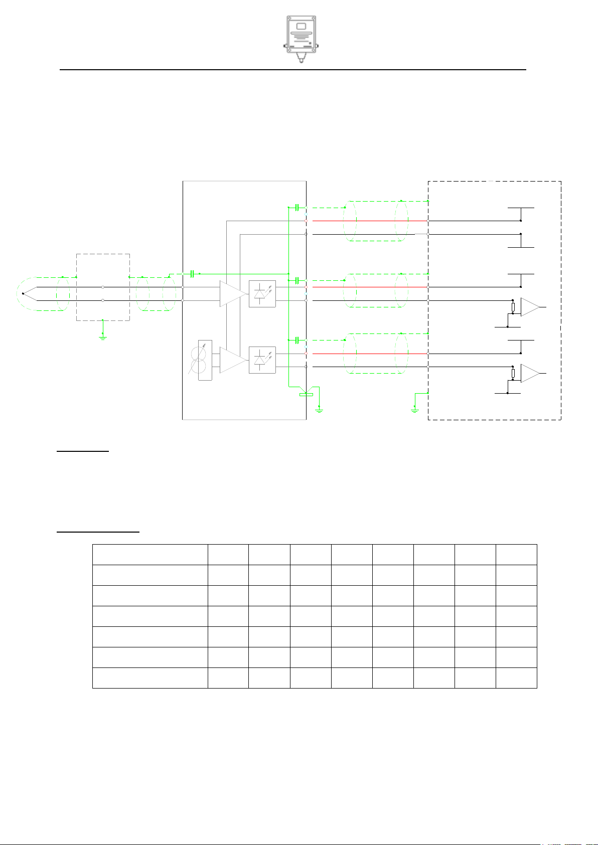
Power receivers
Ui
Ii
Pi
Ci
Li
Uo
Io
Po
Units
V
mA W uF
mH V mA
mW
PS 1
30
200
1.2 0 0
PS 2
30
200
1.2 0 0 4-20mA 1
30
200
1.2 0 0
4-20mA 2
30
200
1.2 0 0
RS232
30 0 0
13 3 50
Thermocouple
Thermocouple
junction box
1
3
E
2
SCREEN
E
3
2
+V RD
1
0V BK
Red Connector
Hydrosteel 7000
Yellow Connector
1
2
Electrical connections (Non IS)
+V RD
0V BK
SCREEN
RD
BK
BK
RD
0V BK
+V RD
SCREEN
+V
+V
0V
0V
3
E
Blue Connector
RD
BK
4-20mA 2
4-20mA 1
Control equipment
Power
+V
0V
Installation
Power and signal requirements
Non Intrinsically Safe (Non IS) applications
Input power 15-24 Volts 35mA
4-20 mA power 8-35 V dc. 22mA
The Hydrosteel is to be wired up as per the wiring diagram below.
WARNING! Non Intrinsically Safe (Non IS) applications
When the unit is installed with a non IS rated power supply the IS details on the front of the unit are not
appropriate for the system. The IS label should be covered up or blocked out. This will prevent safety
discrepancies and or mis-use in the future should the equipment be moved or the site be re-defined as a
hazardous area.
Intrinsically Safe (IS) applications
Entry parameters
For information only see safety certificate before installation
Page 12 of 43
Page 13
Hydrosteel 7000 MANUAL Ion Science Ltd
Unrivalled Detection. www.ionscience.com
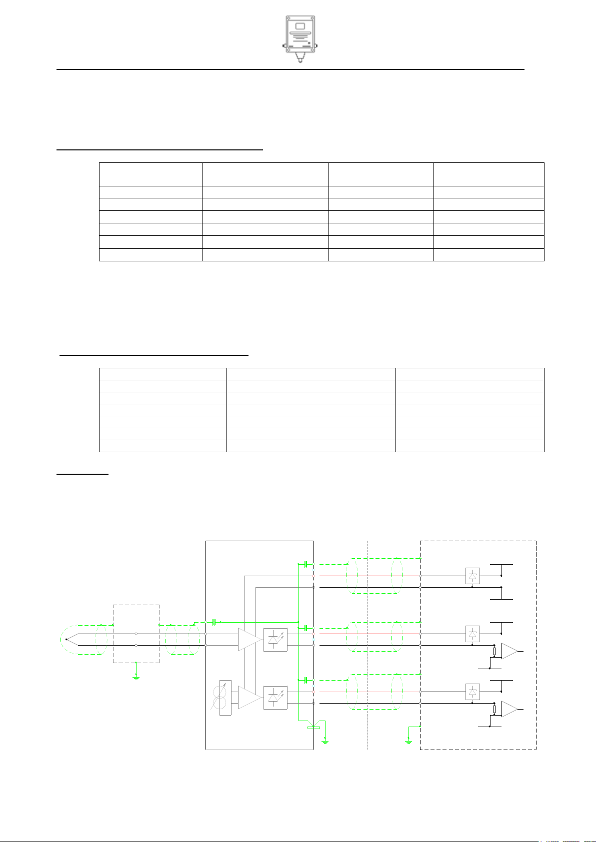
Electrical connections (IS) with safety barriers
Yellow Connector
Thermocouple
junction box
Thermocouple
2
3
E
SCREEN
+V RD
0V BK
Red Connector
SAFE AREA
1
SCREEN
+V RD
0V BK
1
E
3
2
SCREEN
0V BK
+V RD
2
E
3
1
Blue Connector
Hydrosteel 7000
0V
+V
BK
RD
4-20mA 1
0V
+V
0V
RD
BK
Power
+V
BK
RD
4-20mA 2
Control equipment
Manufacture
Manufactures pt. no.
Type
Cable length estimate
m
Pepperl & Fuchs
KFD2-VD-Ex1.1835
Galvanic Isolator
560
Stahl
9175-10-16-11
Galvanic Isolator
335
MTL Ltd
MTL4023
Galvanic Isolator
365
MTL Ltd
MTL7728P
Zener barrier
288
Turck
MK72S06-EX
Galvanic Isolator
686
Manufacture
Manufactures pt. no.
Type
Pepperl+Fuchs
Z728
Zener barrier
Pepperl+Fuchs
KFD2STC4-Ex1
Galvanic isolator
MTL
MTL7787 (dual channel)
Zener barrier
MTL
MTL5044 (dual channel)
Galvanic isolator
Stahl
9001/51-280-110-141
Zener barrier
Stahl
9160/13-11-11S
Galvanic isolator
Installation
Ion Science Ltd suggest using the following or similar safety barrier or IS isolator for IS approved
applications. The system must be designed by a suitably trained engineer and approved by the local safety
authority.
Power Supply:
Suggested barriers for INLET power supply
* Note
All cable lengths are estimated for Zone 1 IIC installation of the equipment
Using 1 mm2 C.S.A. conductors S.T.P. cables with capacitance of 250 pF/m, L/R ratio of 25 uH/
conductor resistance at 20 C of 18.4 /Km
Calculation assumes that cables are at 80 C (maximum operating temperature).
Signal Output
Suggested barriers for 4-20mA OUTLET
WARNING! Intrinsically safe (IS) applications
HY7K fuses may not be replaced in the field.
If a fuse is blown the Hydrosteel 7000 will require inspection by Ion Science Ltd or and Ion Science Approved
Service Centre before it is used in an IS application.
Page 13 of 43
Page 14

Hydrosteel 7000 MANUAL Ion Science Ltd
Unrivalled Detection. www.ionscience.com
Hydrosteel 7000
Thermocouple
junction box
Thermocouple
1
0V
SCREEN
0V BK
+V RD
2
E
3
1
2
3
E
SCREEN
+V RD
0V BK
Red Connector
Blue Connector
4-20mA 1
4-20mA 2
0V
+V
+V
BK
RD
BK
RD
Electrical connections (IS) using galvanic isolator and alternative grounding
SCREEN
+V RD
0V BK
1
Yellow Connector
E
3
2
Power
+V
0V
RD
BK
Control equipment
SAFE AREA
IS Galvanic
Isolator
Screens no longer grounded
at the control equipment end
Capacitors and Power OV shorted
to ground stud inside HY7K
JB earth
Note: JB earth and HY7K earth must be
equi-potential and have no more than 1 Ohms
resistance between them
HY7K earth
Installation
Use of Galvanic isolator and alternative grounding
Galvanic isolators may be used instead of safety barriers in the above circuit. If an isolated supply is used,
the supply at the instrument should be checked for AC noise. Measure the AC voltage between the 0 V and
the local earth. If there is AC noise this needs to be removed. It might be due to a faulty power supply or
induction of AC onto the cables. To remove the noise it might be necessary to ground the 0 V to an earth
point either in the control equipment or at the HY7K instrument. For electrically noisy environments the
optimum grounding is shown in the wiring diagram below. It is essential to follow the following key rules:
1. Screens may only be grounded at one end.
2. If the Power supply 0 V is grounded at the Hydrosteel then a suitable rated Galvanic isolator must be
used.
Cable Requirements
To meet the EMC compliance for immunity it is required that power and 4-20 mA current loops are supplied
with screened twisted pairs. Pairs should be individually screened with the screens terminated in the safe
area and to the terminals on the Hydrosteel 7000. (Note the Hydrosteel does not allow DC earth loops to
ground down the screens).
Removal of cladding and insulation
Hydrosteel flux measurement requires intimate contact between the probe plate and test surface, so it is
necessary to remove any insulation from the target sites.
For ease of access during probe installation, cladding and insulation should be removed from a 1 ft distance
from the centre of the site for flux monitoring. Additionally, if the probe is to be fixed with banding (to pipes
and vessels of less than 32” diameter), insulation and cladding must be removed from the entire
circumference of the vessel or pipe under test.
Preparation of test site
The surface should be free from ridges such as weld filets which could prevent the collector plate from
making intimate contact with the steel surface.
The identified test site surface should be at least 4”, in diameter, to accommodate both the probe and
magnetic thermocouple assembly. This surface should be free from rust and flaking paint which might
otherwise prevent hydrogen flux from exiting the steel surface.
Page 14 of 43
Page 15

Hydrosteel 7000 MANUAL Ion Science Ltd
Unrivalled Detection. www.ionscience.com
Installation
HY7K probe installation
The probe consists of the AT-S probe the background probe and the Thermocouple probe. The AT-S probe
may be fixed in place using magnets or banding depending on the test site geometry. The background probe
is attached to the AT-S probe using clips. The thermocouple probe is magnetic and may be placed directly
on to the surface of magnetic steels.
AT-S and background probe installation with banding
Components
To affix the probe, you will need two equal lengths of banding appropriate for the target pipe diameter. That
is the pipe circumference plus 30 cm for tool operation and fitting of buckles. Ion Science recommends that
standard 3/8” (9.31 mm) width 0.015” (0.38 mm) gauge Stainless steel banding and buckles be used. This
uses a specialist band-tightening tool. Banding kit may be purchased as an accessory.
Items required are:
AT-S probe collector plate
Back ground probe
Probe clips A-910227
Band tensioning tool
Band cuters
x2 Banding buckles
x2 Banding lengths to suit pipe (3/8” - 0.015” guage)
Wire bush for preparing the metal surface
PPE (personal protective equipment)
Pre-assembly
Best done in a clean environment off-site,
Assemble the background probe on to the AT-S probe using the probe clips.
Prepare the banding by cutting it to length. Equal to the Pipe circumference plus approximately 30
cm. For difficult installations longer lengths may be required with the banding being cut afterwards to
remove the excess.
Fit the buckles to the banding following the manufactures instructions
Fit the banding into the support bracket on the AT-S.
Manually adjust the collector so that it is located at a distance equal to ¼ of the target pipe
circumference from the buckle end of the strap. Loosen or tighten the butterfly nuts as required.
Ensure the collector cap is secured to finger tightness.
Page 15 of 43
Page 16

Hydrosteel 7000 MANUAL Ion Science Ltd
Unrivalled Detection. www.ionscience.com
Installation
If it is desired to measure the flux on opposite sides of a pipe e.g the 12 O’clock and 6 O’clock (top
and bottom) then a second AT-S probe may be fitted to the same banding. Fit the seconds AT-S
probe at length of three quarters of the target pipe circumstances along the banding.
Relocation to target site
A hot work permit is not required for installation of the probe as the requirements are purely
mechanical and non-destructive.
Ensure you are equipped with the collector assembly, banding assemblies, band tensioning tool
suitable PPE (personal protective equipment), and a stiff wire brush to remove loose rust from the
test site if necessary.
Step 1: Check again that you can access the entire circumference of the target pipe section and that it is free
from loose rust. Use the wire brush to remove residual rust if necessary.
Step 2: Fit the collector plate to the appropriate place and pass the banding round the pipe circumference;
secure this into the buckle and tension following the manufacturer’s instructions. For hot pipes, it is very
important to let the banding heat up to the temperature of the pipe as the banding will expand and lengthen.
In these circumstances, tension the banding using the tightening tool and leave the tool in place for sufficient
time for the banding to reach temperature, re-tension the banding as necessary before locking the banding
off.
Step 3: Check that the probe is held correctly in position and that they are fully pressed against the piping
surface, particularly at the probe perimeter points identified in the accompanying diagrams.
Page 16 of 43
Page 17

Hydrosteel 7000 MANUAL Ion Science Ltd
Unrivalled Detection. www.ionscience.com
Installation
Also check that the bands are fully parallel. NB: The probe can slide along the banding by loosening the
thumbscrews on the probe brackets, provided the banding is not too tight onto the pipe. Check the banding
buckles are a reasonable distance from the plate so that the banding runs flat against the steel surface and
then onto the collector plate. If the band buckles are very close to the collector edge the banding may not
pull the collector plate flat on to the surface with no or only a very small gap.
Step 4: Lock off the banding as normal, following the banding manufactures instructions. Wait 3-5 minutes!
Due to expansion of the banding attached to pipe at elevated temperatures, it may require tightening after
some time. Re-check probe tightness and positioning as per step 3 and retighten or refit banding as
necessary.
Step 5: Position the background probe so that it is sampling from the edge of the plate.
Page 17 of 43
Page 18

Hydrosteel 7000 MANUAL Ion Science Ltd
Unrivalled Detection. www.ionscience.com
A
x
i
s
o
f
A
x
i
s
o
f
A
x
i
s
o
f
Axis of pipe or vessel:
Note magnet orientation
Installation
AT-S Probe Installation with Magnets
Step 1: Press the collector plate against the target steel surface so that it conforms to pipe or vessel
curvature.
Step 2: With the probe held in place, attach the magnets as shown in the diagram below. Note: The max
working temperature for magnets are 800F 426C
Thermocouple installation
Care should now be taken to prevent the magnet from
tugging the thermocouple lead. The thermocouple is
semi-flexible and further care must be taken when
handling to prevent damage by repeated flexing of the
lead at a single point.
Max working temperature for magnets is 800F 426C
The magnet thermocouple should be fitted so the magnet
legs bridge across the pipe or vessel curve near the
location of the mounted probe, as illustrated below.
Once fitted the screw should be tightened using an Allen
key, until the thermocouple tip is pressed firmly against
the steel as illustrated. (Care should be taken when
doing this as excess tightening could crack the ceramic
block)
Re-insulation and cladding
Weather shielding for the probe is essential to prevent
water ingress blocking the sample flow and preventing
operation. This may be achieved by installing insulation
and cladding with the use of sealing bungs or tape.
Alternatively a custom made cloche might be used
for exposed pipes or where insulation is not needed. Ion
science recommends that a short segment of insulation
capped at each end is used to cover the probe. (See the
diagram below).
Page 18 of 43
Page 19

Hydrosteel 7000 MANUAL Ion Science Ltd
Unrivalled Detection. www.ionscience.com
Installation
The cladding joints and probe exit from the cladding should be sealed with a suitable sealant to prevent the
ingress of water. This arrangement has a number of advantages:
The insulation around the probe is isolated from the general equipment insulation by the cap. This will
prevent / reduce water that gains access through damaged cladding from penetrating to the area of the
probe.
When inspecting the integrity of weather protection only the short section of insulation needs to be
inspected.
When repairing the cladding, checking for water ingress or inspecting the probe only the short section
needs to be opened.
The test site should be insulated and clad with the probe thermocouple and AT-S probe now in place. Note
that the AT-S probe and ambient gas probe caps should not be removed during this procedure; in order to
prevent insulation debris and fibres from entering them. The probe capillaries will withstand flexing to about
2" radius; however, flexing of the thermocouple lead should be minimised. It is essential that the AT-S probe
plate remains firmly in place, and is not distorted by tugging of the capillary conduit.
Make sure the probe cap is in place. The free ends of the probes and sample conduit should either be
pushed through a hole in the insulation as it is laid over them, or a slit can be made in the insulation to
accommodate them.
Page 19 of 43
Page 20

Hydrosteel 7000 MANUAL Ion Science Ltd
Unrivalled Detection. www.ionscience.com
Installation
A hole in the cladding should be formed to enable the AT-S probe, ambient gas probe, and thermocouple to
emerge approximately radially from the pipe or vessel. A 60 mm cavity such as one for UT inspection ports is
often suitable, together with a rubber bung with a radial slit through which the probe capillaries and
thermocouple lead emerge.
Installation of sample conduit
Fixing of probe conduit bracket
It is unlikely that the sample conduit, routed from the probe to the analyser, is of exactly the correct length.
Generally it is preferable to loop spare conduit at or near the analyser terminus and to work from the secured
probe towards it.
The probe bracket is affixed to the 10 m sample conduit and must be secured to enable the AT-S, ambient
gas probes, and thermocouple lead to be attached to it. Generally, it will be necessary to fix the bracket to
outside of the pipe cladding. The probe bracket may be banded, riveted or bolted into position. It is
important to ensure;
Secure support for the probe bracket, as it prevents forces being loaded onto the probes if the
conduit is tugged.
Page 20 of 43
Page 21

Hydrosteel 7000 MANUAL Ion Science Ltd
Unrivalled Detection. www.ionscience.com
Installation
Conduit and tails do not rest against hot piping or equipment. As they contain thermoplastic
components that may be damaged.
WARNING!
Sample Conduit and tails must not be exposed to elevated temperatures above 100 C. These temperatures
can easily be experienced if the conduit or tails are in surface contact with high temperature process pipes.
Connection of probes to sample conduit
Remove the probe caps. Simply attach the AT-S and ambient gas probes manually using the threaded
unions provided. Ensure that the correct capillaries are attached to the correct conduit cable
Tube with nut marked F (red tube or red cable tie) to AT-S probe
Tube with nut marked B (white tube or white cable tie) to
background probe.
Tighten the conduit nuts securely (1/8 turn) using 11mm
spanners.
Use cable ties through the slots in the probe bracket to hold
the probe connections in place.
Connection of thermocouple cables
The thermocouple lead terminates in two wires; these must be connected to the thermocouple cable in the
conduit at the thermocouple junction box. To maintain the continuity of the thermocouple screen, EMC
cables glands supplied must be used. Clamp the thermocouple pot into the cable gland. The internal
conductive spring tabs will make electrical contact with the thermocouple sheath and the pot will be
mechanically secured when the seal is compressed tight. Please see photographs below that follow.
Page 21 of 43
Page 22

Hydrosteel 7000 MANUAL Ion Science Ltd
Unrivalled Detection. www.ionscience.com
Installation
If it has not already been terminated, terminate the thermocouple conduit cable into the gland, bend the
screen wire back and jam it between the insert and the housing. Please see the photographs below.
Connect the thermocouple wires using the terminals inside
the junction box. The thermocouple junction box is mounted
onto the probe bracket so it is fixed in place when the
bracket is fitted to the pipe cladding. A ground connection
should be made from the thermocouple bracket to the local
earth for the purposes of screening. This earth may be
through the contact between probe bracket and cladding.
However if the cladding is electrically isolated or of a non
conductive material an earth connection should be made
directly to a stud on the probe bracket.
Fixing of sample conduit
Use P clips (1/HF-02) and M5 screws or bolts (not
supplied) to fix the conduit to appropriate refinery structures
or cable trunking from the probe bracket towards the
analyser location. Avoid structures which are liable to exceed 100 oC.
Page 22 of 43
Page 23

Hydrosteel 7000 MANUAL Ion Science Ltd
Unrivalled Detection. www.ionscience.com
Installation
Mounting of Hydrosteel 7000 analyser
Dimensions for mounting are shown below. The Hydrosteel 7000 can be mounted in any orientation, except
upside down, which does not cause entry of water into the exhaust port, for example, during drench testing.
Page 23 of 43
Page 24

Hydrosteel 7000 MANUAL Ion Science Ltd
Unrivalled Detection. www.ionscience.com
Commossioning
Commissioning is a matter of terminating the probe and electrical connections to the Hydrosteel 7000 unit
checking the installation and confirming correct operation. The commissioning consists of the following sub
sections:
Inspection of the equipment installation
Terminate probe connection to Hydrosteel 7000
Terminating power and 4-20 mA cables to Hydrosteel 7000
Start-up
Operation test
Hand over
Inspection of the equipment installation
The installation should be inspected prior to commissioning. The following is a check list of features for
inspection:
Probe (if accessible):
Clean test surface, without ridges such as welds
Secure fitting with the collector plate firmly pressed against the test surface
Protect the probe from ingress of water
Probe bracket to sample conduit:
Secure
Free of features that might present a danger to personnel
Sample tube:
Be fixed securely so that is safe from foreseeable damage
Hydrosteel 7000 mounting
Secure and accessible
Sample conduit and electrical connections accessible for connections.
Electrical cables
Continuity of cable cores has been tested
Insulation resistance between cores and between cores and screen has been tested
Connection of cables to correct services has been tested
In a hazardous area, the Power and 4-20 mA cables are labelled so that correct connections can
be made to the Hydrosteel
Page 24 of 43
Page 25

Hydrosteel 7000 MANUAL Ion Science Ltd
Unrivalled Detection. www.ionscience.com
Cut back 30 mm of outer
sheath.
Remove aluminum foil
Commissioning
Probe connection to Hydrosteel 7000
Termination of sample conduit with Han connector
1. Fit Harting connector assembly to the Hydrosteel 7000. This assembly is complete with a special Cable
gland.
2. Offer the sample conduit from the probe up to the Hydrosteel 7000 and mark the required length of the
spiral sheath where it will enter the cable gland on the Harting connector.
3. To maintain traceability of the pneumatic lines after cutting. Mark the tubes above the point at which they
are to be cut so that they may be differentiated (using a wrap of insulating tape is an ideal marking).
4. Pull the spiral conduit so that it extends by at least 30 cm. Cut through the conduit using a hacksaw. By
extending the conduit this ensures that the sub components (pneumatic tubes and thermocouple) have a
30 cm excess protruding from the conduit when it relaxes.
5. If it has not been possible to mark the tube or the marking has been
lost the lines must be traced through by blowing or sucking on the
tube.
6. Fit the M20 conduit adapter (1/HG-03) to the sample tube conduit.
7. The cable gland supplied may be one of two types. Type one uses a
sealing epoxy compound, type two uses a machined rubber gland. If
cable gland that use’s a sealing compound is supplied, then the
sealing compound should not be applied until the sample conduit has been completed to ensure correct
fit. The cable assembly should be fitted dry, following the fitting instructions supplied with the cable
gland. Split the cable gland and thread the pneumatic tubes and
thermocouple through.
8. Close the cable gland and tighten following the cable gland fitting
instructions.
9. Trim the nylon tubes and the thermocouple cable so that 10 cm
extends out of the end of the conduit gland. If any extra length is
required, the conduit can be compressed to reveal a greater length of cable and tubes.
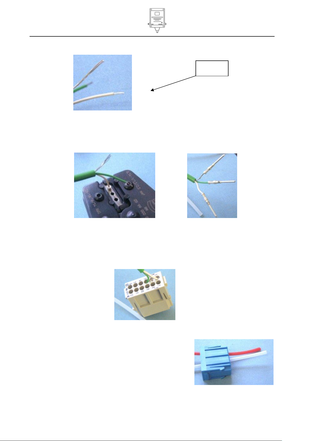
10. On the end of the thermocouple cable strip 30 mm of PVC outside sheath to expose screen and sub
cores.
11. Remove aluminium foil screen to the point of exit from the PVC sheath.
Page 25 of 43
Page 26
Hydrosteel 7000 MANUAL Ion Science Ltd
Unrivalled Detection. www.ionscience.com
Strip 8mm of
insulation
Commissioning
12. Strip 8mm length off white and green wires.
13. Crimp all three wires using crimp contact pins Pt No. 1/JCPB-01. Push the exposed conductor ends into
contact pins. Please Note the screen is tight into crimp socket so don’t twist the conductors together and
tease gently into avoid bending the conductors. If necessary cut 1 or 2 conductor strands out of the
bundle to enable it to fit. Use the end location of “Harting service tool” (Harting part number 09 99 000
0021) to crimp.
14. Feed the nylon tubes and the thermocouple cable through the male reducer and Han connector housing.
15. Fit crimps into Han DD module (1/JSIB-01) from the rear. The rear of the module is the flat fully
numbered sided. The crimps should be fitted as follows according to the numbering on the Han DD
module. Pin 1 = white, pin 2 = screen, pin 3 = green. Use “insert tool” (Harting part number 0999 000
0171) (or with care a small flat blade screw driver) to push crimp sockets until they are securely located.
(Note: to remove the crimps from the sockets if they are incorrectly placed or require maintenance the
“Harting extraction tool” is required.
16. Check the adapter and M20 cable gland parts are tightly fitted to the Han connector housing.
17. Feed nylon tubes through the pneumatic module (1/JNIB-01).
Flux through position 1 and background through position 2.
Since both tubes are natural in colour marking using black tape
for background and red tape for flux has been fitted to the unterminated end. This may have been lost when the conduit was
cut to length. If so trace through the liens by blowing or sucking.
Page 26 of 43
Page 27

Hydrosteel 7000 MANUAL Ion Science Ltd
Unrivalled Detection. www.ionscience.com
Note orientation
Hing
Commissioning
18. Fit the pneumatic connectors on to the nylon tubes.
19. Snap the pneumatic connectors into the pneumatic module.
20. The Han frame ((1/JFIB-02) hinges to allow fitting of the insert modules from the rear.
21. Note frame and modules have keyways to allow only one orientation of fitting. The Aand B arrows
point to the top of the pneumatic module. With the pneumatic module on the side marked with capital
“B”
22. Fit the frame into the Han connector housing.
Page 27 of 43
Page 28

Hydrosteel 7000 MANUAL Ion Science Ltd
Unrivalled Detection. www.ionscience.com
Commissioning
23. Join the gland housing together.
24. Check the full assembly has been assembled correctly. If cable gland supplied requires the use of a
sealing epoxy, open the cable gland and follow the fitting instructions supplied with the cable gland.
Apply the sealing compound. The cable gland must be closed before the sealing compound has cured.
25. Once complete, probe connection will be capable of disconnection and reconnection with Hydrosteel
7000. Tighten Han connector screws with flat blade screwdriver to secure the connector.
Additional fixing of conduit if necessary
Use P clips (1/HF-02) and M5 screws or bolts (not supplied) to fix the sample tube conduit to appropriate
refinery structures or cable trunking. Alternatively use cable ties.
Connect conduit to Hydrosteel 7000
Connect the Han connector from the sample tube to the Hydrosteel 7000. Tighten Han connector screws
with flat blade screwdriver to secure the connector.
Terminating power and 4-20mA cable to Hydrosteel 7000
IP67 rated cable connectors are supplied with Hydrosteel 7000 so that the instrument may be quickly
disconnected, and then reinstalled after servicing. These are colour coded using cable ties. Note the
connector pins have been changed to provide key ways and ensure that each connector is individual to the
appropriated panel socket. The connectors will fit cable diameter’s 6-12 mm.
Terminate the cables following to the connectors as show by the commissioning diagram overleaf. If any
connection is not made to the Hydrosteel the mating face of the connector must be protected from water
ingress by the fitting protective caps or covering with a plastic bag.
Page 28 of 43
Page 29

Hydrosteel 7000 MANUAL Ion Science Ltd
Unrivalled Detection. www.ionscience.com
NOTES:
1) REFER TO EC-TYPE EXAMINATION CERTIFICATE FOR INTRINSIC
SAFETY PARAMETERS
2) REFER TO TECHNICAL SPECIFICATION IN MANUAL FOR SUPPLY
VOLTAGES AND CURRENTS
H2 FLUX
SAMPLE TUBE
ASSEMBLY
SAMPLE TUBE FIXING BRACKET
2 2
22
H2 BACK GROUND
PNEUMATICS
PNEUMATICS
HAN PLUG
2
PANEL PLUG
TAGGED BLUE
PANEL SOCKET
TAGGED GREEN
BACKGROUND
PLANT EARTH LOCAL TO PROBE
NOTE PROBE IS ELECTRICALLY
CONNECTED TO SAMPLE TUB
EQUIPMENT UNDER TEST
THERMOCOUPLE PROBE
NATURAL
NATURAL
GREEN
WHITE
12
FLUX
3
2
2
3
3
2
1
1
1
3
21
6
5
4
3
2
1
1
2
3
- +
SCREEN
THERMOCOUPLE
10
9
8
7
11
E
3
2
1
SCREEN
PS1
POWER
SUPPLY 1
BK 0V
RD +V
FREE PLUG
TAGGED YELLOW
PANEL SOCKET
TAGGED YELLOW
EARTH POST
MUST BE CONNECTED TO
LOCAL (PLANT) EARTH TO
PROVIDE EFFECTIVE SCREENING
HAN RECEPTACLE
4-20mA 1
E
1
2
3
E
SCREEN
SCREEN
0V BK
+V RD
PANEL PLUG
TAGGED RED
FREE SOCKET
TAGGED RED
4-20mA 2
1
0V BK
RS232
CONNECTION
Red / Alarm
LED
Green / power
LED
FREE SOCKET
TAGGED BLUE
BK
+VRD
BK
0V
+V
0V
0V
+V RD RD
3
RD
BK
0V
+V
0V
Control equipment
Hydrosteel 7000
Hydrosteel 7000 Commissioning Diagram
Commissioning
Page 29 of 43
Page 30

Hydrosteel 7000 MANUAL Ion Science Ltd
Unrivalled Detection. www.ionscience.com
Detector
Range
Resolution
Accuracy
4 mA
20 mA
10 mA
Flux (AT-F probe)
0 pl/cm2/s
2400 pl/cm2/s*
1 pl/cm2/s
10 % at cal. Value
Pipe temp
-40 C
500 C
2 C
2 C at cal value
Commissioning
Start up
Power up intrinsically safe circuit. Green LED on Hydrosteel 7000 should light to show correct power
is available to the unit. (the measurement cycle will start automatically)
Power up 4-20 mA circuit. 4mA should register on each circuit.
If any discrepancy from the above is encountered see fault finding and diagnostics in the
Maintenance section
Operation test
Basic test
1. Allow the Hydrosteel to complete one measurement cycle (10+ minutes from switch on). If the green
LED is continuously lit, the power is confirmed as correct. If the Green LED starts to flash then the power
dropped below 15 V (browned-out) during the measurement cycle and it has restarted. See fault finding
and diagnostics in the Maintenance section.
2. If the red LED illuminates, a fault has occurred during the measurement cycle. See fault finding and
diagnostics in Maintenance section.
3. Perform a data download. Check that no diagnostics have failed during the first measurement cycle. If
any diagnostics have failed again, please refer fault finding and Diagnostics in the Maintenance section.
4. The flux reading can be correlated by using a Hydrosteel 6000 close to the Hydrosteel 7000 probe point.
Record a Flux reading on the hand over document.
5. The pipe temperature can be correlated by measuring the temperature at the probe steel surface or by
connecting the Thermocouple to a hand held thermocouple thermometer. Record the first thermocouple
reading on the hand over document.
Test if Hydrosteel function test is available
1. Disconnect the flux (AT-S) probe and connect hydrogen flood leak sample conduit.
2. Allow the Hydrosteel to complete one measurement cycle (10+ minutes from switch on).
3. Perform a data download.
4. The flux reading should be between 280 pl/cm2/s and 380 pl/cm2/s. Record the flux reading on the hand
over document.
5. The pipe temperature can be correlated by measuring the temperature at the probe steel surface or by
connecting the thermocouple to a hand held thermocouple thermometer. Record the first thermocouple
reading on the hand over document.
4-20 mA test
1. Both 4-20 mA outputs should be 4mA from unit switch-on of the 4-20 mA power supplies for each output.
After the first measurement cycle is complete the 4-20 mA output will be up dated to reflect the current
reading.
2. The 4-20 mA output after the first measurement cycle can be ascertained by performing a data download
and using the flux and pipe temperature readings to calculate the 4-20 mA outputs. See the table below:
3. Note: Flux 4-20 mA output range may be changed see Hydrsoteel setup section.
4. Check the initial 4 mA reading and any subsequent readings have been correctly measured by the 4-20
mA receivers.
5. Program the correct units and range for each output into the “data collection system”. See the table
above.
Page 30 of 43
Page 31

Hydrosteel 7000 MANUAL Ion Science Ltd
Unrivalled Detection. www.ionscience.com
Commissioning
Hand over
1. With the permission of the owner, photograph the unit as installed. The photographs will provide a
documentary record of sound installation. Photographs should show the following.
Correct probe installation
Probe is securely mounted and safe from foreseeable damage
Sample conduit has been mounted securely and is safe from foreseeable damage
HY7K is mounted securely and is safe from foreseeable damage
All connections have been made securely to the HY7K and are safe from foreseeable damage
2. Produce hand-over document with the following details:
Customer details
Customers PO no
Hand-over date
Site or location reference
Equipment tag number or other reference
Add the photographs
Operation test results
First flux and pipe temperature measurements
3. Have the installation inspected and the hand-over the signed document.
Page 31 of 43
Page 32

Hydrosteel 7000 MANUAL Ion Science Ltd
Unrivalled Detection. www.ionscience.com
Hydrosteel setup
Clock time
The clock is set to GMT at factory. When unit is interrogated using data download package. The time
associated with data points will be automatically adjusted to the time zone set on the computer operating
system (Microsoft windows). Whenever a previously saved data file is opened the times are not adjusted.
If the instrument clock time is incorrect for any reason, it can be reset using the data download software.
Note that the time is set with reference to the clock on the computer; this must be correct before the clock in
the instrument is set. See Data download software for further instructions.
Flux 4-20mA output range
The Flux 4-20mA range default is 4mA = 0 pl/cm2/s and 20 mA = 2400 pl/cm2/s. This may be change to 20
mA being from 1 pl/cm2/s to 2400 pl/cm2/s using the “Flux 4-20 mA range” calibration option in the
“instrument” menu of the DDP. The Flux range is variable so that it may be optimised for the corrosion
application. Please refer to the applications manual or contact Ion Science for assistance.
Operation
One switched on the Hydrsoteel will operate continuously. Every 10 minutes the HY7K will data log and
output over 4-20 mA loops new readings.
As users you may decide for a full integrated system where the 4-20 mA data is collected by a data collection
system (DCS) and is available immediately for daily use in optimising a process. Alternatively the data log
may be relied upon to collect the data. The data would then be analysed periodically in conjunction other
corrosion and process data. The analysis and use of data is outside the scope of this manual. Please refer to
the Hydrosteel applications manual or contact Ion Science Ltd for technical support.
To download data the Data Download Program is needed. This is software that should be installed on a
portable PC so that it may be connected to the HY7K using an RS232 cable, (and if necessary USB adapter
supplied). The section below details the operation of the Software. The Hydrosteel has a number of internal
diagnostics. If one of these detects a fault then it will be displayed as a red LED on the outside of the
instrument, output on the 4-20 mA and saved in the data log. See maintenance section for full details.
Page 32 of 43
Page 33

Hydrosteel 7000 MANUAL Ion Science Ltd
Unrivalled Detection. www.ionscience.com
Hydrosteel 7000 PC software
The PC software is designed solely to allow the download and viewing of data recorded using the Hydrosteel
7000 unit. Once downloaded data files may then be stored on any computer system and opened for review
as needed. The data is displayed in two formats; graphically and as a table of data entries with each row
being the data recorded for a given measurement cycle.
The software follows a standard windows format for main functions and is therefore self-explanatory for
common operations such as open file, save file etc.
Installation of Hydrosteel Software
PC Requirements
Hydrosteel Software must be used in conjunction with a PC/laptop using Microsoft Windows 98 or later.
First remove any older version of “7K PC software” if they are installed. This is done using “Add / remove
programs” option in the Microsoft windows control panel. Select 7K PC from the list and click on the remove
button. Note in “Add / remove programs” it may be necessary to pan to the bottom of the list using the scroll
bar to find the 7K PC listing. This is because Microsoft has a large number of blanked out entries in the
middle that look like the list has ended when in fact they are just hidden.
1. Double click the file called “7K PC setup.exe” located on the Ion Science software CD
2. Follow the on screen prompts saving the software in a drive of your choice (typically your C drive).
3. Click on the 7K PC icon in the ISL directory to start the software. This is found in the Microsoft start “all
programs” menu.
On start-up of 7K PC software a quick start menu appears with the most likely initial commands, Open file,
Connect to Instrument, Settings and Close.
Open file - Allows a file previously saved to the PC memory to be viewed.
Connect to Instrument – connects to the Hydrosteel 7000 for data download.
Settings – enables the user to select the coms port for connection to the instrument or search for a
Hydrosteel 7000 instrument connected to one of the coms ports.
Setup of USB to RS232 coms port
If the Lap –top or PC does not have a dedicated coms port then the USB to RS232 coms port adapter
supplied with the Hydrosteel kit should be used. Follow the instructions with this item to load the drivers and
set up the operation.
Connecting to the Hydrosteel 7000
1. Connect modem cable from PC coms port to Hydrosteel 7000 coms port. Make sure the instrument is
switched on.
2. Start the 7K PC software and select settings. Note if the USB adaptor is used and is attached before PC
switch on, then the Software will not be able to open the PC coms port. Simply disconnect and reconnect
the USB adaptor to make things operational and continue with the instructions below.
3. Select “Search for instrument”. The PC software will pole the existing com ports in ascending order to
find which port the Hydrosteel is attached to. Once the instrument has been found select OK to continue.
(If the instrument is not found check the power and connections to the HY7K and if necessary use
another coms port).
4. Select “connect to instrument” A window will appear as the software attempts to communicate to the
Hydrosteel 7000. The top box will confirm the instrument status if the connection has been correctly
made. If the communication fails an error message will be displayed “error failed to get data”. See Fault
Finding, under ‘Operation’.
Page 33 of 43
Page 34

Hydrosteel 7000 MANUAL Ion Science Ltd
Unrivalled Detection. www.ionscience.com
Hydrosteel 7000 PC software
The Connect to instrument window
Instrument status - reflects the diagnostic situation of the instrument
Current status and Historic status confirm the current operation and flag if a diagnostic fail has occurred in
past operation (since switch on or last data download) respectively. See Diagnostics, under ‘Operation’.
Instrument Details – gives the following information on the instrument
Instrument serial number
Instrument firmware version
Clock (This is the current date time stamp from the instrument Clock)
Data of first stored record
Last calibration date
Download options
Download data from – this accept a date time to short the download.
Download data
Download calibration – This is for ISL servicing of instruments
Memory dump – This is a last resort option if the memory has become corrupted
Downloading data
Each Hydrosteel 7000 has its own unique serial number. This number is printed on the front of the unit and
contained in the unit software. All data downloaded from an instrument is stamped with this serial number.
This allows data from multiple units to be distinguished. The serial number is displayed at the top of the
graph and data table, and also saved to the top of a “*CSV” export file.
Data download
1. To download the data press download button. There is an option to download data only from a specific
date. This might be the date of the last data download. A status bar will appear while the data downloads
if the memory is full (1year +) this will take some time.
2. One the data has downloaded it will be displayed as graph and table.
3. Save the data as required
Erasing logged data
Once the data has been downloaded and saved we recommend that the logged data is erased. This will
minimise the data download time and prevent multiple files having the same data.
Graph operation
The graph automatically plots the flux data. For graph options use the graph drop down menu on the tool
bar or right click with the mouse on the graph. Option include different data plots, horizontal and vertical
gridlines or liner/stair-step interpolation.
A data point can be selected by clicking on graph with the mouse. The corresponding data point in the table
will be highlighted blue.
A region of data points can be selected by clicking and dragging on the graph again the data points will be
highlighted blue on the graph and table.
Zoom in
To zoom in select "zoom in" icon (Magnifying glass with a doted box), point the mouse pointer at a corner of
the area to zoom in on, click the left mouse button, and drag a zoom box over the required area then left
mouse click again. The graph will zoom in on the boxed region. You may zoom in repeatedly as needed.
Page 34 of 43
Page 35

Hydrosteel 7000 MANUAL Ion Science Ltd
Unrivalled Detection. www.ionscience.com
Hydrosteel 7000 PC software
Zoom out
Use the magnifying glass icon with the minus sign in the middle to zoom out to view complete data set.
Use the magnifying glass icon with the undo arrow to return to the last zoom section.
Status bar
The status bar at the bottom of the graph above the table will indicate Green for correct operation yellow for
off and red if there was a diagnostic fault detected with the instrument reading. Data displayed in red
indicates a diagnostic flag see diagnostics section on under ‘Operation’.
Data table operation
The table shows the data in chronological order with the first data point at the top of the table. Use the scroll
bar (quickest) or up down arrows to navigate up or down the table. A data point may also be selected with
the mouse. The selected data point will be high lighted on the graph as a fine vertical dashed line. A region
of data points may be selected using the arrow keys and holding down the shift key the data selected will be
highlighted blue on the graph and the table.
As a default the table shows the following columns of data:
Date time,
Flux,
Pipe temperature,
Diagnostic flag.
The diagnostic flag will indicate the status of the instrument at the time of the measurement. It there was a
fault it will be stated see diagnostics section for details.
The table may be expanded to show the complete set of readings logged during a measurement cycle by
using the expand/shrink table in the windows drop down menu or the expand shrink icon on the tool bar.
These are listed below:
Date time,
Flux,
Valid - Logged data point check sum valid
Supply - Supply voltage at the instrument
Internal temperature
Pipe temperature
Pump voltage
Pump current
Flow
Background - Hydrogen background reading
Variance
Zero - Hydrogen sensor zero reading
SR - Hydrogen sensor impedance diagnostic SR pins
RC - Hydrogen sensor impedance diagnostic RC pins
SC - Hydrogen sensor impedance diagnostic SC pins
Diagnostic flag
Data handling
The software can create two file types “*.HY7”, and “*.CSV”. The “*.HY7” is specific to the HY7K PC
package, and cannot be opened by another software package. The package is not designed to edit the data
or provide any processing functionality. The “*.CSV” file can be imported into spreadsheet packages such as
Microsoft Excel for editing and performing detailed analysis. In addition to the basic operations of open, save
and export, the user can save file sections to a new file and merge files together.
Page 35 of 43
Page 36

Hydrosteel 7000 MANUAL Ion Science Ltd
Unrivalled Detection. www.ionscience.com
Hydrosteel 7000 PC software
Save section
A specific episode of flux in data can be saved on its own. To save a section, highlight the section on the
graph with the mouse, then select the “Save Section As” option from the file menu. A save data as dialogue
box will appear and ask for a file name and location to save the file.
Merging files
This enables new data to be added to existing files so that a continuous data record is created. Files may
only be merged if they do not contain any overlapping data and are from the same instrument. To merge two
files, open a file and then select merge from the drop down file menu. This will prompt your to select the
second file to merge.
Print options
There are options to print and print preview the displayed graph, table or table section. The graph area
printed will be that on display at the time of printing. Should a particular section be desired for printing then
the zoom and pan functions should be used to select this as the displayed graph area.
As the Hydrosteel is capable of storing large numbers of data points caution should be exercised when
deciding to pint table data as it could run to a very large number of pages. It is possible to print a limited
section of the table. Simply use the curser to highlight a section of the graph in blue which will select the
corresponding table data points. Alternatively select the table data points using the curser arrows. Print table
section will print this section only.
Instrument Settings
There are the following instrument settings that may be accessed using the 7K PC software:
Set Clock
The clock is set to Greenwich Mean Time (GMT) at factory.
When unit is interrogated using data download package, the time associated with data points will be
automatically adjusted to the time zone set on the computer operating system (Microsoft Windows).
Whenever a previously saved data file is opened the times are not adjusted.
The clock can be changed by selecting the “Set Clock/Erase Data” option from the “instrument” pull down
menu and choosing the appropriate option. Note the time is set with reference to the clock on the computer
so this must be correct before the clock in the instrument is set. In changing the instrument clock time all the
data in the memory will be erased to maintain data integrity.
Erase logged Data
If the instrument memory is full, data is stored on a scrolling basis. Use the ‘Erase data’ option only in order
to delete all data from the instrument memory.
Flux 4-20mA Range menu
This menu enables the Flux 4-20 mA output range to be changed. It is necessary for the instrument to be
connected for this operation. Simply connect the RS232 cable activate the “flux 4-20 mA range” window and
follow the on screen prompts.
Firmware Upgrade
This enables the instrument firmware to be upgraded for improved operation. Simply connect the RS232
cable to the instrument with it powered up. Open the 7k PC software select “firmware upgrade” from the
“instrument” dropdown menu and follow the on screen instructions. You will be asked to find the upgrade file
(.upg), this will be provided by ion science by e-mail or CDROM simply select it from it’s saved location.
Once the upgrade is complete switch the instrument on and off to ensure the new program is active.
Warning: The firmware upgrade must not be interrupted or the operation of the instrument is likely to be
corrupted. If this occurs the instrument will have to be returned to Ion science for reprogramming. Ensure
that the modem cable is securely connected and if a laptop is used check the batteries have sufficient power.
Select the “firmware up grade” from the instrument drop down menu and follow the directions. No status bar
will be displayed during the up grade process so patience is required. The firmware upgrade will take some
time. (3-6minutes).
Page 36 of 43
Page 37

Hydrosteel 7000 MANUAL Ion Science Ltd
Unrivalled Detection. www.ionscience.com
Maintenance and calibration
Hydrosteel 7000 unit maintenance
The unit should be checked routinely for operation and re-calibrated yearly. Re-calibration requires that the
unit be returned to Ion Science Ltd for service.
Quarterly maintenance
Inspection of LED, 4-20 mA outputs and diagnostic data should be stored to memory to ensure that it
is running correctly. If the 4-20 mA are used, the diagnostic alarms will be raised as 3.5 mA alarm
signals. It is still advisable to check the LED and then if necessary the diagnostic data as this
provides additional information.
Yearly maintenance
Inspect the LED, 4-20 mA outputs and diagnostic data stored to memory.
Factory calibration and service. This includes testing and possible replacement of H2 sensor, filters,
pump, restriction, back up battery, tubing, valve, fuses.
Note Ion Science does not recommend maintenance in the field that requires the lid to be removed. With the
lid removed the Hydrosteel 7000 analyser is vulnerable to water and dirt ingress.
Probe installation
Hydrosteel probes are made of high temperature tolerant materials and are corrosion resistant. The main
concerns are; blockage of the probes and conduit by water or rust from corrosion of the target surface or
mechanical damage. The following should be inspected yearly and after every shut down:
The sample tube is secure and free from damage
The Han connection to the Hydrosteel 7000 is free from damage
If the probe is accessible check the following:
The conformance to the test surface is correct and the banding is secure
Evidence of corrosion
The probe is free from blockages or dirt debris that may potentially cause a blockage. If
appropriate do a quick pressure decay test. No pressure should be supported if the system is
free from blockages.
If the probe is covered by insulation check the following:
Inspect at the entry point that no damage has occurred to the probe
Check that insulation is secure, sealed and free from external damage that might allow water
ingress. Water that penetrates the insulation may block the probe directly or cause corrosion of
the test surface under the probe. This corrosion is likely to block the air flow during sampling.
Check that the thermocouple is functioning. See the diagnostics table for more information.
Page 37 of 43
Page 38

Hydrosteel 7000 MANUAL Ion Science Ltd
Unrivalled Detection. www.ionscience.com
Symptom
Cause
Check
No LED lights
No power,
Incorrect wiring
Fuse has blown
Ensure that there is 15 V d.c. across the power
terminals at the unit. Check the polarity; that
the positive wire goes to the + terminal.
If the voltage and polarity have been incorrectly
applied then the fuse may have blown. Note if
the fuse has blown the instrument will need to
be returned to Ion Science Ltd.
Green LED flashes
continuously. *
Insufficient power unit keeps
on resetting
Ensure that there are 15 V across -+ power
terminals at the unit.
* Note the green LED will go off for 2-3 seconds
when the pump starts.
Green with alternate
quick Flashes of the
Red LED
Fault has occurred since last
data download or last
operation. Fault is not
currently present and unit is
operating correctly
Perform a data download and look at the log of
diagnostics to identify the fault. See diagnostics
matrix below for resolve the issue.
RED LED lights
Unit has self diagnosed a
fault
Download data to find out specific diagnostic
failure. See diagnostics matrix below for resolve
the issue.
4-20 mA = 0mA
No loop power or incorrect
wiring
Ensure that there is >8 V across -+ power
terminals at the unit.
Check that positive wire goes to the + terminal.
4-20 mA = 3.5mA
Unit has self diagnosed a
fault with given
measurement. 4-20mA 1=
flux measurement ,
4-20mA 2 = pipe
temperature measurement
Download data to confirm fault and follow fault
diagnostics matrix over leaf.
RS232 connection fails
Communication parameters
incorrectly set.
Incorrect modem cable.
Check red or green LED is lit
as fuse may have Blown.
Check com port settings
Check the null modem cable used
If the fuse has blown then the coms will not
operate. The unit needs to be returned to Ion
Science Ltd for servicing.
Fault finding and diagnostics
Fault findings
WARNING!
Ensure plant safety before starting maintenance. Certified test equipment should always be used unless a
gas clearance certificate has been issued.
The following table lists the fault outputs and their consequences. Please contact Ion Science or your local
Hydrosteel representative if you need any assistance.
Page 38 of 43
Page 39

Hydrosteel 7000 MANUAL Ion Science Ltd
Unrivalled Detection. www.ionscience.com
Diagnostic Flag
Red
LED
On
4-20 mA 1
Flux output
3.5 mA
4-20 mA 1
Temp output
3.5 mA
Recommended action
Clock fault
Yes
Clock lost from memory
The data points will be saved sequentially in
the memory log. Reprogram the clock time
and date using the DDP program.
Background flow
fault
Yes
Yes
Back Ground Flow incorrect
Check the background probe and sample tube.
In some extreme cases the blockage may be
at the filters inside the HY7K. A pressure decay
test may be instrumental in proving the tubes
are free from blockages. The most common
form of blockage is water. If water has
penetrated that system then the tubes will
need to be blown out with dry air and the
weather protection afforded to the probed will
need to be investigated.
H2 Flow Fault
Yes
Yes
Flux Sample Flow incorrect
Check the background probe and sample tube.
In some extreme cases the blockage may be
at the filters inside the HY7K. The most
common form of blockage is water. If water
has penetrated that system then the weather
protection afforded to the probed will need to
be investigated.
Hydrogen
sensor faulty
Yes
Yes
Hydrogen sensor faulty
Return HY7K for servicing. The Sensor is not
working reliably
Thermocouple
fault
Yes Yes
Thermocouple open circuit
Check the thermocouple connections and
continuity. Note the pipe temperature recorded
in the data log will be 615 C as an indication
of this fault.
Temperature
out side
operating range.
Yes
Yes
HY7K monitor internal temperature is
less than -40 C or greater than +50 C.
Investigate the local temperature. If the
instrument is too close to hot equipment then
it should be relocated to a cooler place. If the
ambient temperature is excessively cold then
the HY7K will be situated in a heated location.
Diagnostics and fault finding
Diagnostics
The diagnostics are saved to the memory with each measurement cycle results. These can be examined by
downloading the logged data. In addition the unit will alarm using the Red LED and 4-20mA outputs. The
table below shows the diagnostic faults and the actions that should be taken:
Page 39 of 43
Page 40

Hydrosteel 7000 MANUAL Ion Science Ltd
Unrivalled Detection. www.ionscience.com
Operating Temperature
-10 to 50 C (-14 to 122 F)
Storage Temperature
-25 to 50 C (-13 to 140 F)
Zone 1/2 Safe Operating Temperature
-40 to 60 C (-40 to 140 F)
IP rating monitor
IP66 (note unit should not be mounted upside down)
Technical specifications
Environmental
IP66 (note unit should not be mounted upside down)
IP rating probe IP40, The weather resistance of the probe and hence the Hydrosteel system is dependant
on the probe installation. Caution; the probe must be sheltered from water and dust ingress as this will block
sample flow and prevent operation.
Mechanical
Monitor Dimensions & Mounting points monitor
Connector gland sizes for cable OD’s
1: 6-12 mm
2: 6-12 mm
4-20mA #1: 6-12 mm
4-20mA #2: 6-12 mm
Monitor Weight ~2.6 kg 5.75 lb
Monitor Materials Glass filled polyester case
Electrical Power requirements:
PS1: 15-24 V @ 34 mA
PS2: Spare. Contact Ion Science Ltd if power available for PS1 is not
sufficient due to local intrinsic safety requirement
4-20 mA #1: 9-30 V @ 2-20 mA (loop powered)
4-20 mA #2: 9-30 V @ 2-20 mA (loop powered)
Page 40 of 43
Page 41

Hydrosteel 7000 MANUAL Ion Science Ltd
Unrivalled Detection. www.ionscience.com
Detector
Range
Resolution
Accuracy
Flux (AT-F probe)
0 to 2400 pl/cm2/s
1 pl/cm2/s
10% at cal. value
Pipe temp
-40C to +615C
1C
2C at cal. value
Internal temp
-40C to +125C
1C
1C at cal. value
Flow
0 to 60 ml/min
0.1 ml/min
5% at cal. value
Probe diameter
144 mm
Probe length
10 m (30 ft)
Probe head length
320 mm inc. allowance for 90 bend
Probe conduit diameter
16 mm
Probe conduit bend radius
35 mm
Detector
Range
Resolution
Accuracy
4 mA
20 mA
10mA
Flux (AT-F probe)
0 pl/cm2/s
2400pl/cm2/s *
1 pl/cm2/s
10% at cal. Value
Pipe temp
-40C
500C
2C
2C at cal value
Technical specifications
Communications
RS232 via a standard modem cable terminated with male and female 9-pin Sub-D connector at each
end. Cable length <3 metre. A USB- RS232 adaptor may be used.
4-20 mA output for flux
4-20 mA output for pipe temperature
Measurements
Logged to memory:
4-20mA output:
Note Range output range is variables from 1 to 2400pl/cm2/s and is selected using the Data
Download Package.
Memory
The memory will record approximately 18 months of data. Once memory is full data is logged in a first in first
out rolling cycle by memory sector.
Diagnostics
Operating temp -40 C to 60 C
H2 sensor Electrolytic conductivity
Flow 30 ml/min +/-3%
Power alarm Insufficient supply voltage
Visual Alarm Via red LED on instrument
Transmitted alarm 3.5 mA on 4-20 mA outputs
Log to memory
Operating lifetime
Pump 10,000 hr cumulative use
Probe Dimensions
Probe fixing
Banding for >4” up to 32”
Magnets for large diameter pipes where banding not practical. (max working temperature 800F 426C).
Note; insulation and cladding are highly recommended and are essential if weather protection is required.
EMC. To achieve the immunity detailed above all wiring should be screened twisted pairs.
Page 41 of 43
Page 42

Hydrosteel 7000 MANUAL Ion Science Ltd
Unrivalled Detection. www.ionscience.com
USA Office
Ion Science LLC
33 Commercial Drive
Waterbury
VT 05676
USA
Tel: +1 802 244 5153
Fax: +1 802 244 8942
Email: info@ionscienceusa.com
Web: www.ionscience.com
UK Head Office
Ion Science Ltd
The Way, Fowlmere
Cambridge
SG8 7UJ
UK
Tel: +44 (0)1763 207206
Fax: +44 (0) 1763 208814
Email: info@ionscience.com
Web: www.ionscience.com
German Office
Ion Science Messtechnik GMBH
Laubach 30
Metmann-Neandertal
40822
GERMANY
Tel: +49 2104 14480
Fax: +49 2104 144825
Email: info@ism-d.de
Web: www.ism-d.de
Instrument warranty and service
Warranty
Standard Warranty can be extended to up to 2 years on the Hydrosteel 7000 when registering
your instrument via our website: www.ionscience.com/instrument-registration
To receive your Extended Warranty, you need to register within one month of purchase (Terms
and Conditions apply). You will then receive a confirmation email that your Extended Warranty
Period has been activated and processed.
Full details, along with a copy of our Warranty Statement can be found by visiting:
www.ionscience.com/instrument-registration
Service
Ion Science is pleased to offer a number of service options on our Hydrosteel 7000 product
range that allow you to choose the instrument cover that best suits your needs.
At Ion Science we recommend that all of our gas detection instruments be returned for service
and factory calibration once every 12 months.
Contact Ion Science or your local distributor for service options in your area.
Find your local distributor by visiting: www.ionscience.com
Contact details
Page 42 of 43
Page 43

Hydrosteel 7000 MANUAL Ion Science Ltd
Unrivalled Detection. www.ionscience.com
Manual
Version
Amendment
Date
updated
Instrument
Firmware
PC Software
Hydrosteel
7000 V2.5
Update log added in back
of manual
23/12/08
V68
DEV080617.01
Hydrosteel
7000 V2.6
Page 12 – Added Pipe
info
Page 20 – Letters
overlapping sorted
13/01/09
V68
DEV080617.01
AR08060
Hydrosteel
7000 V2.7
Certificates of conformity
up dates after standards
review on AR0806
2/03/09
V68
DEV080617.01
Hydrosteel
7000 V2.8
Page 32 - print options
added to PC SW. Note on
use of RS232 adapter.
Software installation
instructions.
P35 - firmware upgrade
instructions.
23/06/09
V80
DEV090621.01
Hydrosteel
7000 V2.9
Warranty added on cover
Declaration of conformity
updated
Contents updated
Warranty and Service
added page 42
23/07/10
V80
DEV090621.01
Hydrosteel
7000 V3.0
Pages 1&4 updated to
correct Quality
Management System
Page 4 Responsibility of
use updated and legal
notice added
03/03/11
V80
DEV090621.01
Hydrosteel
7000 V3.1
Manual layout and format
updated
10/12/12
V80
DEV090621.01
Manual log
Page 43 of 43
 Loading...