

Page 1
DOCUMENT APPROVED FOR GENERAL DISTRIBUTION
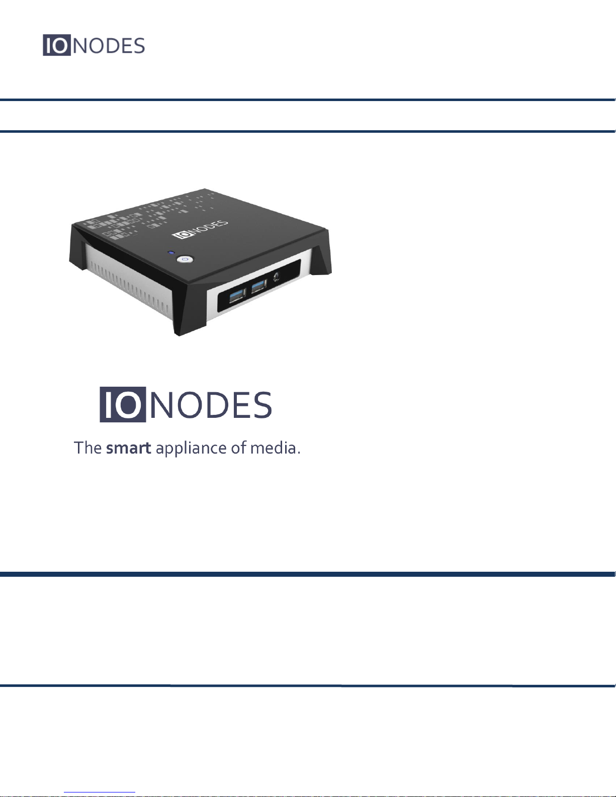
ION-R200
User Manual
Version 1.0
IONODES INC.
www.ionodes.com
Page 2
ION-R200 – User manual
ION-R200
User Guide
©2016-2017, IONODES INC
All Rights reserved.
No part of this documentation may be reproduced in any means, electronic or mechanical, for
any purpose, except as expressed in the Software License Agreement. IONODES shall not be
liable for technical or editorial errors or omissions contained herein. The information in this
document is subject to change without notice.
The information in this publication is provided “as is” without warranty of any kind. The entire risk
arising out of the use of this information remains with recipient. In no event shall IONODES be
liable for any direct, consequential, incidental, special, punitive, or other damages whatsoever
(including without limitation, damages for loss of business profits, business interruption or loss of
business information), even if IONODES has been advised of the possibility of such damages
and whether in an action or contract or tort, including negligence.
This software and documentation are copyrighted. All other rights, including ownership of the
software, are reserved to IONODES Inc. Windows and Windows Embedded Standard are
registered trademarks of Microsoft Corporation. All other brand and product names are
trademarks or registered trademarks of the respective owners.
The following words and symbols mark special messages throughout this guide:
Warning: Text set off in this manner indicates that failure to follow directions could result in dam-
age to persons or equipment.
Note: Text set off in this manner indicates special instructions which should be paid attention
to.
Page 3
ION-R200 – User manual
Page 3 of 49
Table of Contents
1 IMPORTANT SAFETY INSTRUCTIONS ....................................................................................... 5
2 CLEANING INSTRUCTIONS ......................................................................................................... 6
3 HANDLING NOTES ........................................................................................................................ 6
4 MOISTURE AND CONDENSATION NOTES ................................................................................. 6
5 BEFORE YOU BEGIN .................................................................................................................... 7
5.1 ABOUT THE ION-R200 ............................................................................................................... 7
5.2 PARTS LIST ............................................................................................................................... 8
6 HARDWARE INSTALLATION ....................................................................................................... 9
6.1 EQUIPMENT INSTALLATION ......................................................................................................... 9
7 CONNECTIONS ............................................................................................................................ 10
7.1 FRONT PANEL .......................................................................................................................... 10
7.2 REAR PANEL ........................................................................................................................... 11
7.3 TOP PANEL .............................................................................................................................. 12
8 POWERING THE ION-R200 FOR THE FIRST TIME ................................................................... 13
9 DEVICE CONFIGURATION ......................................................................................................... 15
9.1 NETWORK CONFIGURATION BASICS .......................................................................................... 15
9.2 SETTING UP THE INITIAL NETWORK CONFIGURATION LOCALLY ................................................... 16
9.3 SETTING UP THE INITIAL NETWORK CONFIGURATION REMOTELY ................................................ 19
9.4 SETTING UP THE WIRELESS NETWORK ..................................................................................... 23
9.5 SETTING UP THE TIME .............................................................................................................. 24
9.5.1 Setting Up the NTP time server ......................................................................................... 25
9.6 VIDEO CONFIGURATION CONCEPTS .......................................................................................... 26
9.7 CONFIGURING VIDEO CONNECTIONS ......................................................................................... 27
9.7.1 Video Data Sources ........................................................................................................... 27
9.7.2 Displaying a Data Source .................................................................................................. 31
9.7.3 On-Screen Displays ........................................................................................................... 33
9.7.4 Displaying an On-Screen Display ...................................................................................... 36
9.8 CONFIGURING WEB CONNECTIONS ........................................................................................... 37
Page 4
ION-R200 – User manual
Page 4 of 49
9.9 CONFIGURING VIEWS ............................................................................................................... 39
9.10 CONFIGURING VIDEO OUTPUTS ................................................................................................ 40
10 PERFORMING A FIRMWARE UPDATE .................................................................................. 43
10.1 BATCH FIRMWARE UPDATE ...................................................................................................... 44
11 DIAGNOSTICS ......................................................................................................................... 46
11.1 VIEW STREAM DETAILS ............................................................................................................ 46
11.2 SAFE MODE ............................................................................................................................. 47
ANNEX A – STATEMENT LIMITED WARRANTY .............................................................................. 49
Page 5
ION-R200 – User manual
Page 5 of 49
1 Important Safety Instructions
WARNING: Read and save these instructions! Follow all warnings and instructions
specified within this document and/or on the equipment.
CAUTION: The unit will be powered on upon connecting a valid power supply source.
Please make sure to properly shutdown the device’s operating system prior to removing
its power source.
The equipment shall be installed in a FIXED or DESKTOP configuration and should be installed
by qualified personnel only (person having the appropriate technical training and experience
necessary for product installation).
When installing the equipment, please make sure that cables are installed so that accidents
cannot occur. Cables connected to the equipment must not be subject to any mechanical strain.
To reduce the risk of fire, electric shock and/or injury, observe the following:
Do not position the equipment as such that persons could walk on the connected cables.
Do not spill any type of liquid substance on or near the equipment.
Do not touch the equipment and its connected cables during an electrical storm; there
may be a risk of electric shock.
Do not attempt to connect this equipment to electrical outlets controlled by switches or
automatic timers.
Do not attempt to perform hardware service on this product yourself. Opening the
equipment casing may expose you to dangerous voltage or other risks. Refer servicing
to IONODES technical service personnel. Never open the device yourself as this will void
the warranty.
The equipment should be situated away from heat sources such as radiators, heat regis-
ters, stoves, or other products that produce heat.
Do not place a heavy object on or step on the product. The object may fall, causing seri-
ous personal injury and serious damage to the product.
Note: Opening the equipment case, damaging or altering the tamper proof label will void the
warranty.
Page 6
ION-R200 – User manual
Page 6 of 49
2 Cleaning Instructions
Unplug this product from the wall outlet before cleaning.
Use a soft dry cloth for cleaning.
For stubborn dirt, soak the cloth in a weak detergent solution, wring well and wipe. Use a
dry cloth to wipe it dry. Do not use any type of solvent, such as thinner and benzene, as
they may damage the surface of the product.
3 Handling Notes
When shipping the product, the original shipping carton and packing materials should to be
used. For maximum protection, repack the unit as it was originally packed at our factory.
Do not use volatile liquids, such as insect spray, near the unit. Do not leave rubber or plastic
products in contact with the product for long periods of time. They will leave marks on the
surface finish.
4 Moisture and Condensation Notes
Moisture condensation will damage the product. Read the following notes carefully.
Moisture condensation occurs during the following cases:
Transferring the product directly from a cold place to a warm place.
Using the product in a room where you just turned on the heater, or a place where the
cold wind from an air conditioning unit directly hits the unit.
In the summer, when moving the product to a hot and humid place after leaving an air
conditioned space.
Using the product in a humid place.
Warning: Do not use the product when moisture or condensation may occur. If the product is
used in such an environment, it may damage discs and internal parts.
Page 7
ION-R200 – User manual
Page 7 of 49
5 Before you begin
5.1 About the ION-R200
The ION-R200 multi-port decoder delivers high quality H.264 video decoding and display to the
video surveillance market. It is an embedded, high-performance digital video decoder, capable
of decoding multiple H.264 video streams and display them on up to two digital displays with up
to 4K resolution.
The high-performance decoding capabilities of the ION-R200 offers a cost-effective way to
decode and display digital camera streams while providing the benefits of video over IP and
wireless networks.
The ION-R200 provides innovative configuration options and tools that can significantly
decrease the amount of time and effort required to deploy a unit. Using web-based configuration
tools, users can easily and remotely manage all aspects of the appliance.
To support high-performance decoding, while keeping the total cost of ownership within budget
constraints, the ION-R200 uses highly efficient hardware-based H.264 stream decompression.
The ION-R200 is fully compatible with H.264 video streams provided by most third-party IP
cameras and video encoders on the market. Combined with the IONODES line of IP-based
video encoders, the ION-R200 can also decode video streams provided by most third-party
analog cameras.
Page 8
ION-R200 – User manual
Page 8 of 49
5.2 Parts List
Qty Description
1 ION-R200 appliance
1 19V DC power supply with country-specific power plug attachments
1 VESA mounting bracket and screws
1 USB utility key
1 Quick install guide
Below are additional items which are not included but may be required:
USB mouse & keyboard
HD Displays (HDMI and / or Mini DisplayPort)
Internet access and/or a network switch
Power bar with surge protection
Note: When unpacking, inspect the shipment box and appliance to identify any possible
damages due to shipping. Make sure all items have been delivered and that no
items are missing. Contact your IONODES representative should you find any damages or defects.
Note: The product serial number label helps the IONODES product support team identify
your device and its factory configuration in the event that your ION-R200 or its components require service. The label is attached on the underside of the enclosure.
Page 9
ION-R200 – User manual
Page 9 of 49
6 Hardware Installation
6.1 Equipment Installation
The ION-R200 can be placed on a flat surface, such as a desktop, or mounted via the available
mounting bracket.
When installing the ION-R200, position the unit to allow for cable clearance at the front and rear
of the unit. Make sure that minimal air flow is provided to the unit.
The ION-R200 can be mounted to various mounting structures via the available VESA mounting
assembly. Ideal to mount the ION-R200 behind a screen. Note that VESA mounting screws are
shipped with the device.
Warning: Be careful not to damage the enclosure when using mounting screws.
Page 10
ION-R200 – User manual
Page 10 of 49
7 Connections
The ION-R200 offers two separate digital video output connections as well as several USB and
audio connections.
7.1 Front Panel
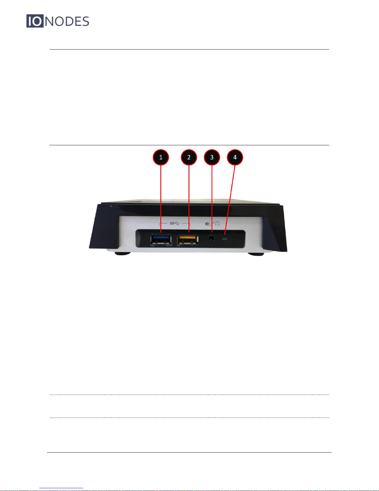
1. 1 x USB 3.0
General purpose USB connector interface. This ports can be used to connect an
optional keyboard or mouse.
2. 1x USB 3.0 (with charging capability – Yellow)
General purpose USB connector interface with charging capabilities. Can be used to
recharge an external USB device.
3. AUDIO IN / OUT
3.5 mm jack which can be used to connect both an audio input and an audio output
source. The stereo channel provided by this connector exposes one channel for the
audio input and the other for the audio output.
Warning: Audio support is currently not implemented on the ION-R200 and may be made availa-
ble in a future software update.
Page 11
ION-R200 – User manual
Page 11 of 49
4. POWER LED
Blue status LED indicating whether the device is powered on or not.
7.2 Rear Panel
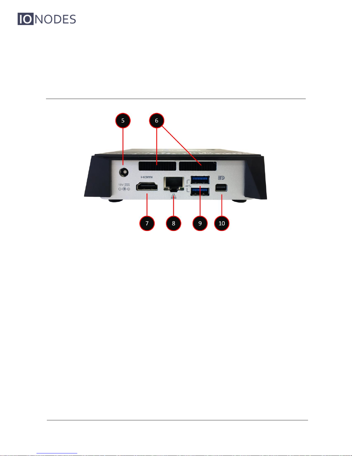
5. POWER
Appliance power connector. Connect to the power supply block provided with the appliance (12V – 19V).
6. AIR VENTS
Please ensure air vents are clear to allow for proper device ventilation.
7. HDMI OUT
HDMI 1.4b connector interface for video output to an HD digital display.
8. ETHERNET
ION-R200 Gigabit Ethernet network port. Please use a straight RJ45 (cat. 5 or 6)
network cable. Note that the ION-R200 cannot be powered using Power-over-Ethernet
(PoE).
9. 2 x USB 3.0
General purpose USB connector interfaces. These ports can be used to connect an
optional keyboard or mouse.
Page 12
ION-R200 – User manual
Page 12 of 49
10. MINI DISPLAYPORT
Mini DisplayPort version 1.2 connector interface for video output to an HD digital display.
7.3 Top Panel
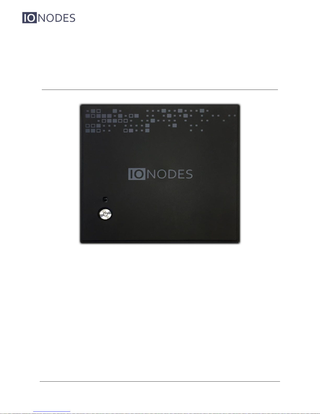
POWER ON / OFF
Button used to boot up or shut down the device. The button includes a LED indicating
when the appliance is powered on.
HDD ACTIVITY LED
Amber status LED indicating hard disk activity.
Page 13

ION-R200 – User manual
Page 13 of 49
8 Powering the ION-R200 for the first time
Before you can use the ION-R200, you need to connect the following cables:
Display(s): You can connect one display using the HDMI connector and/or one display
using the Mini DisplayPort connector.
Ethernet network
Keyboard and mouse (optional)
Power
Connecting a keyboard and mouse to the ION-R200 allows you to configure the ION-R200
locally and for this reason are strongly recommended. If you plan on configuring the device
remotely, then the keyboard and mouse are optional.
Once all the required cabling is connected, press the POWER ON / OFF button on the top panel
of the ION-R200. After a few seconds, the image below appears on all connected displays:
Page 14
ION-R200 – User manual
Page 14 of 49
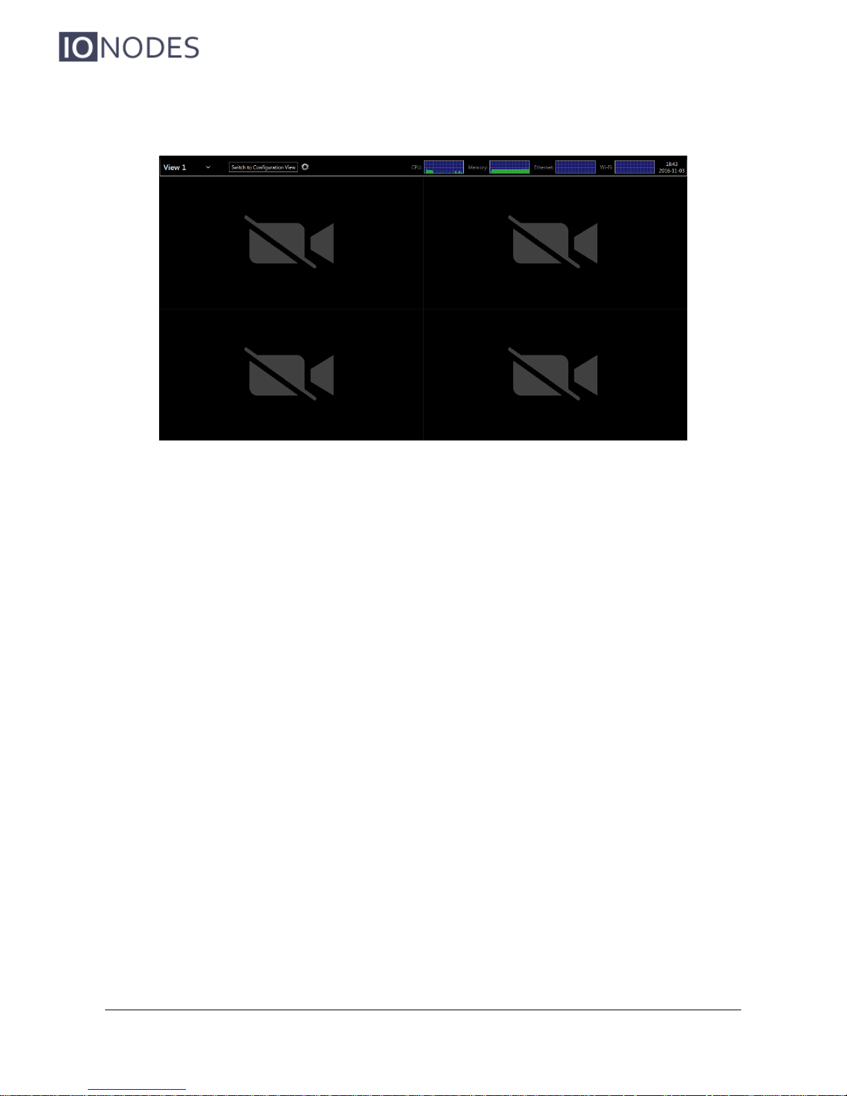
When the device is ready to be used, the displays switch to the main user interface:
The ION-R200 is now ready to be configured.
Page 15
ION-R200 – User manual
Page 15 of 49
9 Device Configuration
Before the ION-R200 can be used on your video network, it must undergo an initial setup step
during which its network configuration is determined. This initial configuration setup step is
required so that the ION-R200 can communicate with computers and cameras on the network.
Once the initial network configuration step is completed, video output and connectivity settings
will need to be set-up through the device’s web interface. The device keeps this configuration
within its internal memory and acts as a fully standalone video decoding & display appliance.
The initial network configuration can be performed directly on the device by connecting a
keyboard and a mouse to the ION-R200, or it can be performed remotely using a computer or
laptop connected to the same network.
9.1 Network Configuration Basics
By factory default, the ION-R200 is configured in DHCP mode (Dynamic Host Configuration
Protocol). In DHCP mode, when the device boots up, if it is connected to a network it scans that
network for a DHCP server. If a DHCP server is found on the network, the device requests that
the DHCP server provide a unique network address and associated settings. The device then
uses the DHCP-provided network configuration to communicate with other computers and
cameras the network.
If no DHCP server is found on the network, the device switches to APIPA mode (Automatic
Private IP Addressing). In this mode, the device automatically assigns itself a unique network
address in the range 169.254.0.1 to 169.254.255.254 with subnet mask 255.255.0.0. APIPA
mode ensures that devices in the APIPA network address range can communicate with one
another.
Page 16
ION-R200 – User manual
Page 16 of 49
If computers and cameras on your network are not configured in APIPA mode, the ION-R200 will
not be able to communicate with them while in APIPA mode. In such a case, the network
configuration of the ION-R200 must be set manually.
When the network configuration is set manually, the ION-R200 skips all the steps above and
always uses the user-provided configuration. It is then the responsibility of the user to ensure
that the network configuration in the ION-R200 is compatible with the computers and cameras
on the network.
9.2 Setting Up the Initial Network Configuration Locally
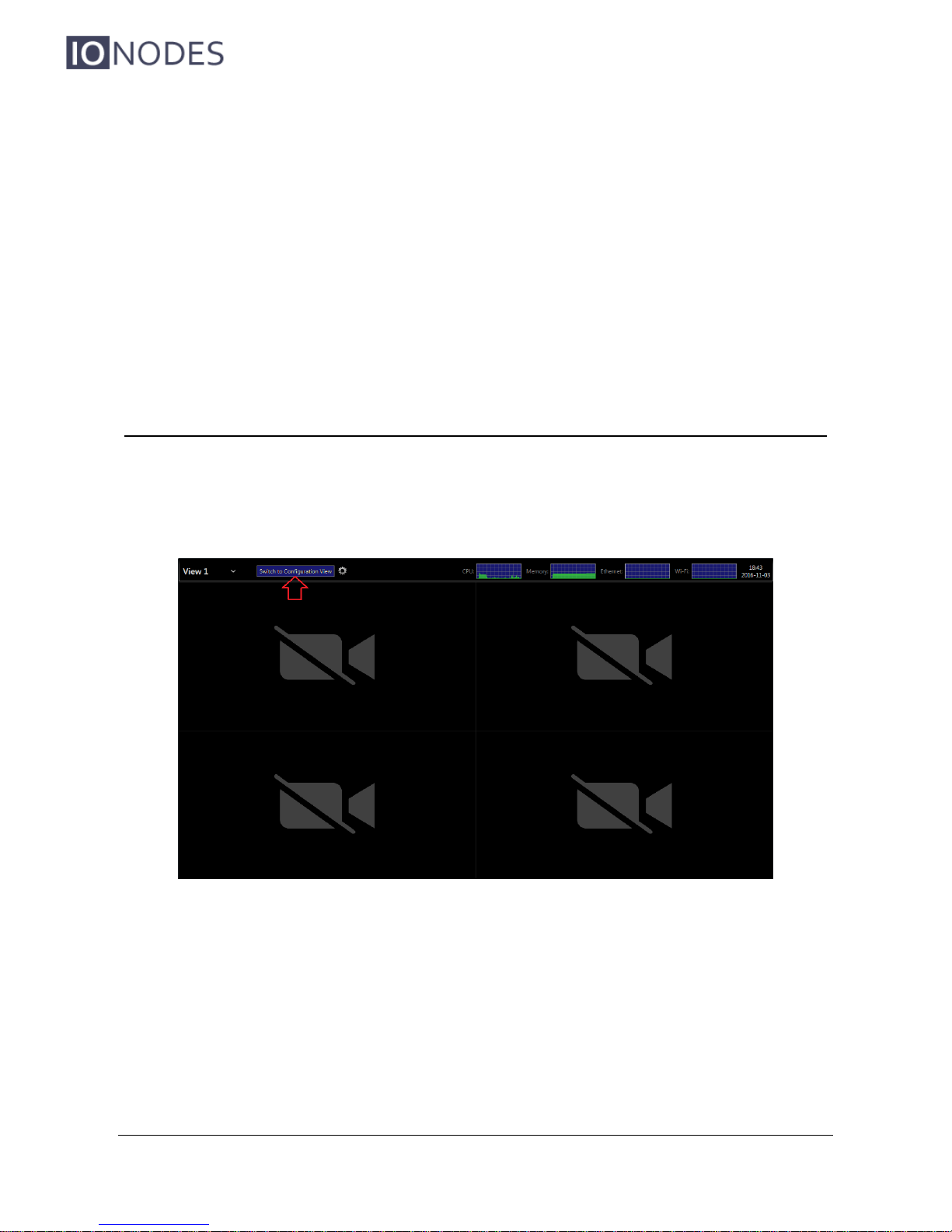
The configuration of the ION-R200 can be accessed on the device itself by switching to the
configuration view.
Page 17
ION-R200 – User manual
Page 17 of 49
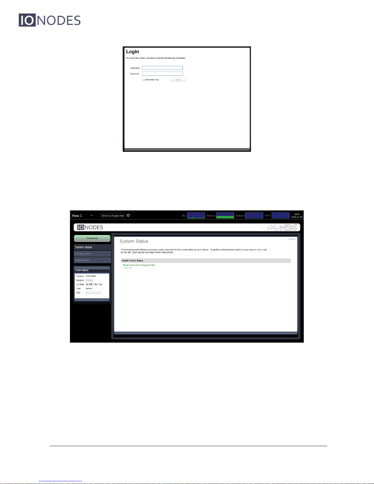
To access the device’s configuration, you must enter a valid username and password. The
factory default user name and password are both ‘admin’. The following screen is then
displayed:
On the left side, select Configuration. The configuration interface is then displayed on the right
side. Select the Network tab to display the network configuration.
Page 18
ION-R200 – User manual
Page 18 of 49
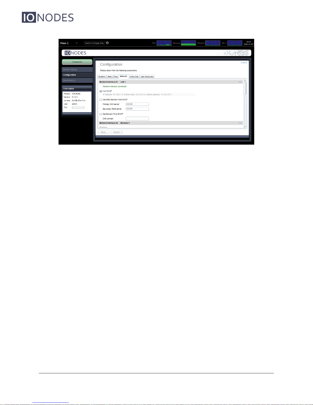
The Ethernet network configuration is shown in the first section Network Interface #1 – LAN 1.
The first information displayed is the connection status of the Ethernet cable. If the configuration
reports the network interface as not connected, check the Ethernet cable between the ION-R200
and the network before proceeding.
By default, the ION-R200 is configured in DHCP mode. If a DHCP server is present on the
network, the network configuration provided by the DHCP server is displayed. In that case,
nothing needs to be done; the device is ready to communicate with computers and cameras on
your network.
If the IP address shown is in the range 169.254.*.*, this means that the device could not obtain
its network configuration from a DHCP server. In that case, the network configuration must be
set manually.
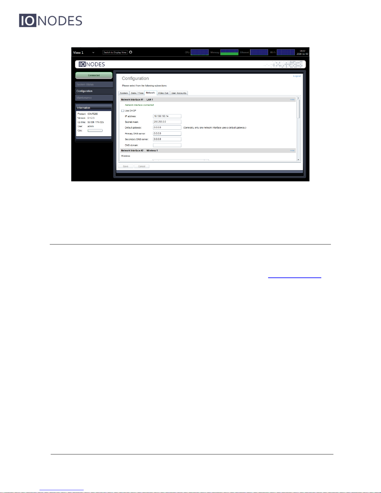
To set the network configuration manually, uncheck Use DHCP. You can then enter each
network setting separately. If you are unsure what values to enter, ask your network
administrator to provide configuration settings compatible with your network. At a minimum, a
valid IP address and Subnet mask must be entered. Once this is done, click on Save at the
bottom to apply the configuration changes.
Page 19
ION-R200 – User manual
Page 19 of 49
The device is now ready to communicate with computers and cameras on your network.
9.3 Setting Up the Initial Network Configuration Remotely
Initial device network configuration can also be done via the ION Configuration Tool (ICT), a tool
provided by IONODES and that can be found on the IONODES web site at www.ionodes.com.
The ICT plays several roles:
1. Discovery of all ION-R200 and other IONODES devices on the network
2. Remote configuration of the IP address and subnet mask
3. Applying batch firmware upgrade of all common IONODES devices
4. Accessing a device’s web based management interface
Once your device is installed on your network and powered up, launch the ICT from any
computer located on the same network as the device.
The ICT supports 2 methods for discovering a device on the network. The first method doesn’t
require any configuration and uses the Bonjour discovery protocol. In order to be able to
discover a device via Bonjour, the network must support multicast IP.
Page 20
ION-R200 – User manual
Page 20 of 49
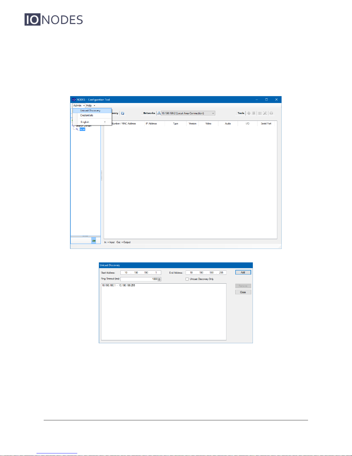
If multicast is not supported, you can use the second method: Unicast Discovery. Unicast
Discovery can be configured by using the “Unicast Discovery” menu option under the Admin
menu list.
To configure Unicast Discovery, add one or more IP address ranges. Unicast Discovery will
attempt to reach a device at a specific IP address in the configured ranges. Discovery can be a
long process if the range of IP addresses is large. To accelerate the discovery, add several
small ranges of IP addresses.
Page 21
ION-R200 – User manual
Page 21 of 49
The ping timeout option can be increased for a high latency network.
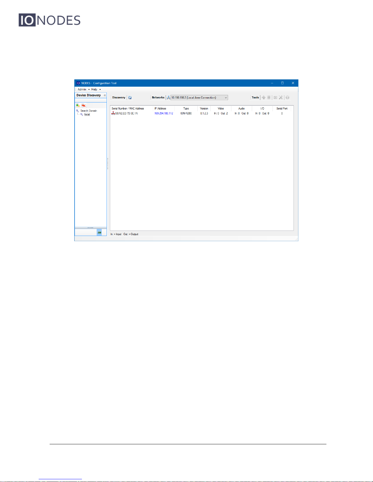
The ICT will display as many devices as it discovers on the network.
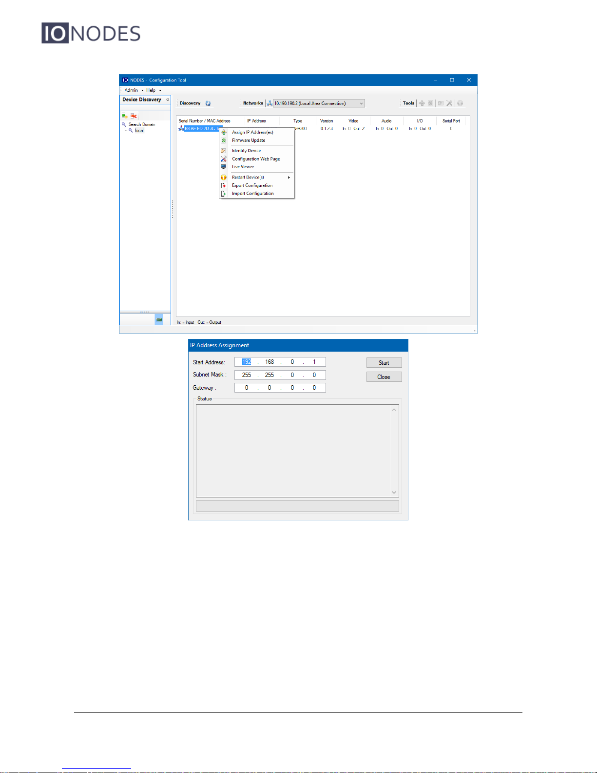
The ICT displays the current IP address of each detected device. If the device is configured in
DHCP mode, its IP address appears in blue.
If a DHCP server is present on your network, it assigned an IP address to the device during the
device’s boot-up sequence.
If no DHCP server was able to assign an IP address to an ION-R200, it will appear in the ICT
device list with an APIPA address (169.254.*.*). If an ION-R200 displays an APIPA address it
must be configured with a valid IP address before it can be used on the network. Select the
‘’Assign IP address’’ from the selection list and apply the desired TCP/IP settings to the device.
Page 22
ION-R200 – User manual
Page 22 of 49
Once the network settings are set, the web-based configuration interface of the ION-R200 can
be launched from the ICT or directly in your web browser by typing the device’s IP address in the
address bar.
Page 23
ION-R200 – User manual
Page 23 of 49
9.4 Setting Up the Wireless Network
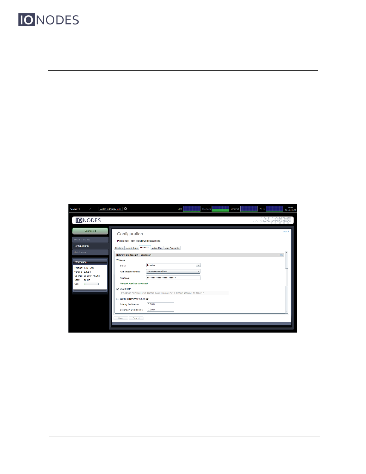
The ION-R200 can also connect to wireless networks. In the Configuration page, select the
Network tab and scroll down to the section named Network Interface #2 – Wireless 1.
The SSID field represents the name of the wireless network. The ION-R200 automatically
detects available wireless networks; simply select from the list the wireless network to which you
want to connect. Enter the password protecting the wireless network and click on the Save
button at the bottom.
Once the wireless settings are filled, configuring the remaining settings works exactly like
configuring the Ethernet network interface (see section 9.2).
Page 24
ION-R200 – User manual
Page 24 of 49
9.5 Setting Up the Time
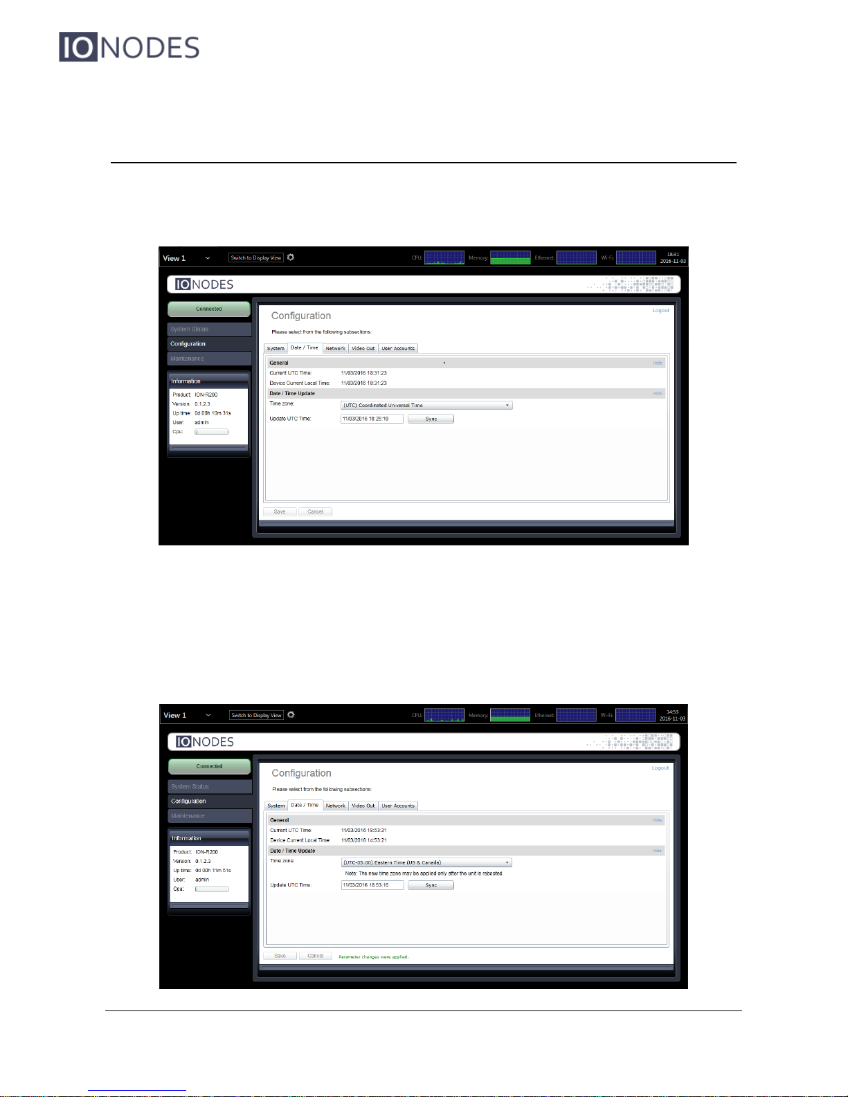
In the Configuration page, select the Date/Time tab.
To set the time zone in the device, select the appropriate value from the list in Time zone. To
set the current time in the device, enter the new UTC time in Update UTC Time. If you are
configuring the time remotely from a computer, clicking on Sync automatically uses the current
UTC time of the computer.
Page 25
ION-R200 – User manual
Page 25 of 49
Click the Save button to apply the changes.
Note: Changing the time zone requires the device to be rebooted before the change takes
effect.
9.5.1 Setting Up the NTP time server
Some networks use a time server, also named NTP time server (Network Time Protocol). The
role of a time server is to synchronize the time for all devices on the network. The ION-R200
can be configured to use such a time server to synchronize its internal clock.
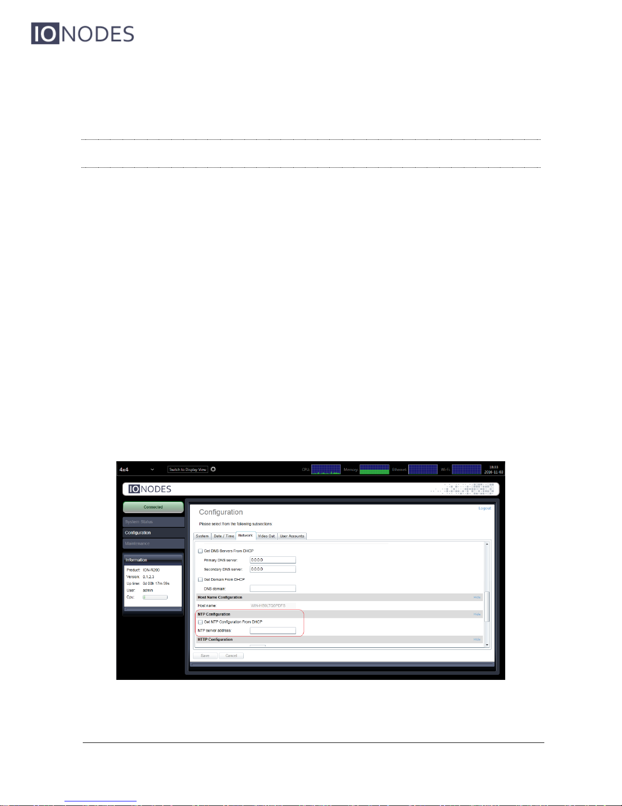
In the Configuration page, select the Network tab and scroll down to the NTP Configuration
section. Set the proper NTP server address under the NTP Configuration header. Click the
Save button to apply the changes.
If the device is configured in DHCP mode and the DHCP server is set up to provide the address
of the NTP time server, you can check Get NTP Configuration From DHCP. Click the Save
button to apply the changes.
Page 26
ION-R200 – User manual
Page 26 of 49
9.6 Video Configuration Concepts
In the Configuration page, then select the Video Out tab. The video configuration is divided in
4 sub-tabs:
Data Sources
On-Screen Displays
Views & Tiles
Video Outputs
Data sources represent connections to external devices. Two types of connections are currently
available: RTSP video streams and web pages. The ION-R200 supports up to 32 separate data
sources.
On-Screen Displays (OSD) determine the information you want to display over video streams
and how to display that information. For example, when displaying a video stream, you might
want to display the camera name and current time over the video. The ION-R200 supports up to
32 separate OSD configurations.
Views determine how you want to group and display data. For example, if you wanted to display
video from all the building entrances on one screen in a 2x2 layout, you could configure a view
to do so. The ION-R200 supports up to 5 separate views.
Finally, display outputs contain the configuration specific to each TV or monitor connected to the
ION-R200, like the display resolution for example. The ION-R200 supports up to two display
outputs (one HDMI and one Mini DisplayPort).
Page 27
ION-R200 – User manual
Page 27 of 49
9.7 Configuring Video Connections
9.7.1 Video Data Sources
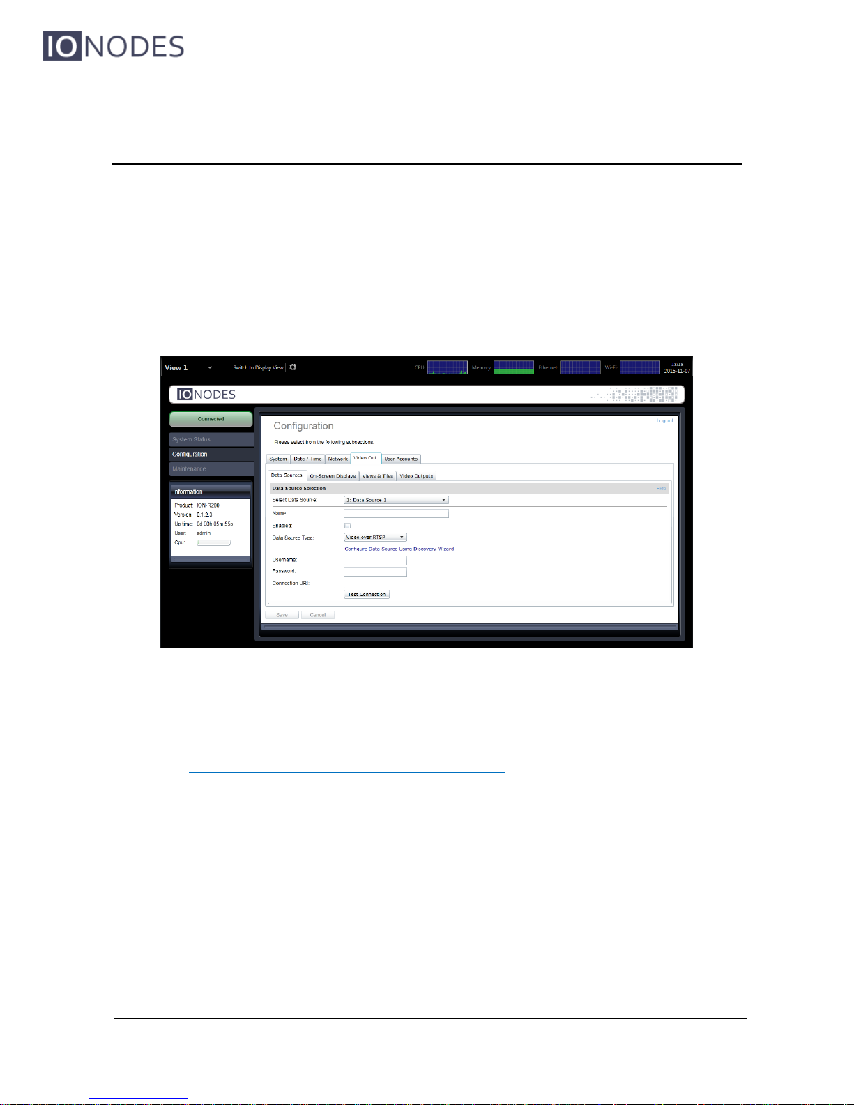
In the Configuration page, select the Video Out tab, then the Data Sources sub-tab. After
that, select the data source you want to configure. To configure an RTSP video connection, set
Data Source Type to Video over RTSP.
To connect to a video stream, the ION-R200 needs to know the Connection URI as well as any
Username and Password required by the camera or encoder. If you know the exact connection
URI of the video stream, you can type it in manually. Or you can use the discovery wizard by
clicking on Configure Data Source Using Discovery Wizard. The discovery wizard guides you
through a few simple steps in order to fill the data source configuration for you.
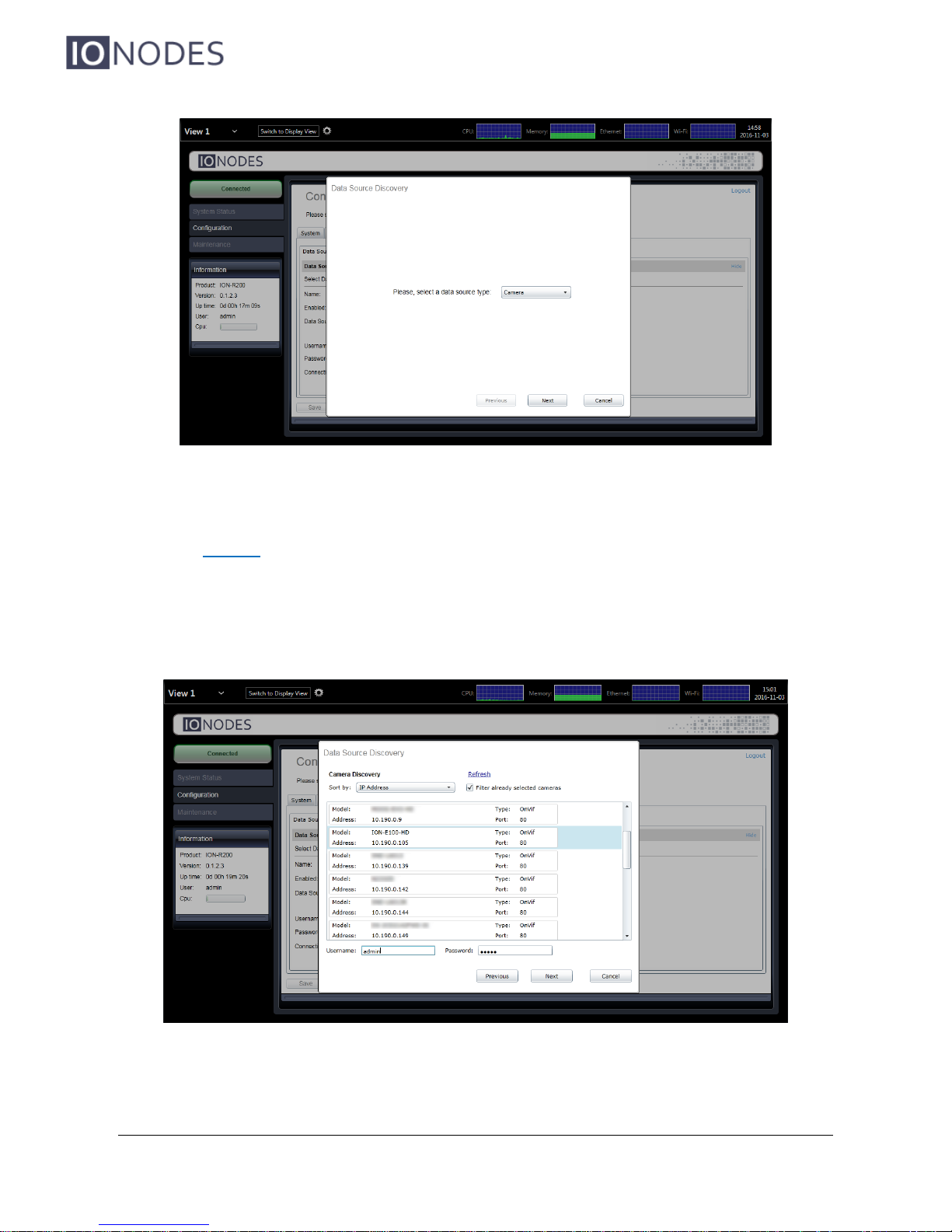
In the first step of the discovery wizard, set the type of data source to configure to Camera and
press Next.
Page 28
ION-R200 – User manual
Page 28 of 49
The wizard then displays a list of all cameras and encoders on the network. If the camera you
are looking for does not appear in the list, make sure the camera is connected to the network
and press Refresh.
Select the camera you want by clicking on the desired entry in the list. Then, enter the
Username and Password required to connect to the camera. Press the Next button.
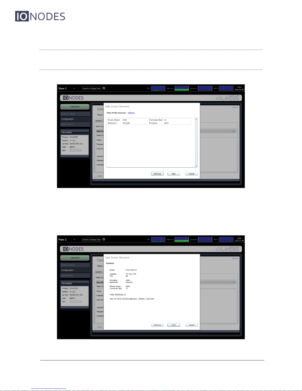
In this step, the wizard displays a list of all video streams available from the camera that are
supported by the ION-R200. Click on the desired video stream, then press Next.
Page 29
ION-R200 – User manual
Page 29 of 49
Note: If you entered a wrong username or password in the previous step, the wizard dis-
plays a warning indicating that it can’t connect to the camera. In this case, press the
Previous button to go back and enter the correct username and password.
Here the wizard displays the details of the video stream you have selected. To confirm that this
is the video stream that you want, click on Finish. The wizard then closes and the data source
configuration is automatically populated.
Page 30
ION-R200 – User manual
Page 30 of 49
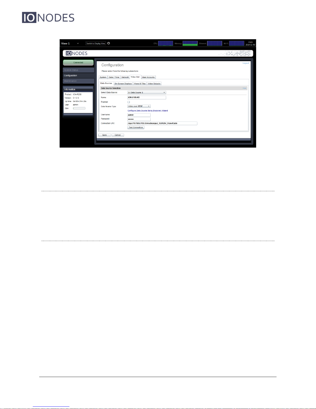
To finalize the data source configuration, type in a name (optional) for the data source. Check
Enabled to enable this data source and press Save at the bottom to save the new configuration.
Note: The ION-R200 connects to a video stream ONLY when that video stream is dis-
played. Enabling a data source indicates that the ION-R200 can establish this connection when needed, not that it needs to do so right away. Disabling a data source
prevents the ION-R200 from connecting to the video stream for any reason.
Note: A video data source creates a single connection. Even if the video is played on two
different outputs at the same time, the video stream is captured only once.
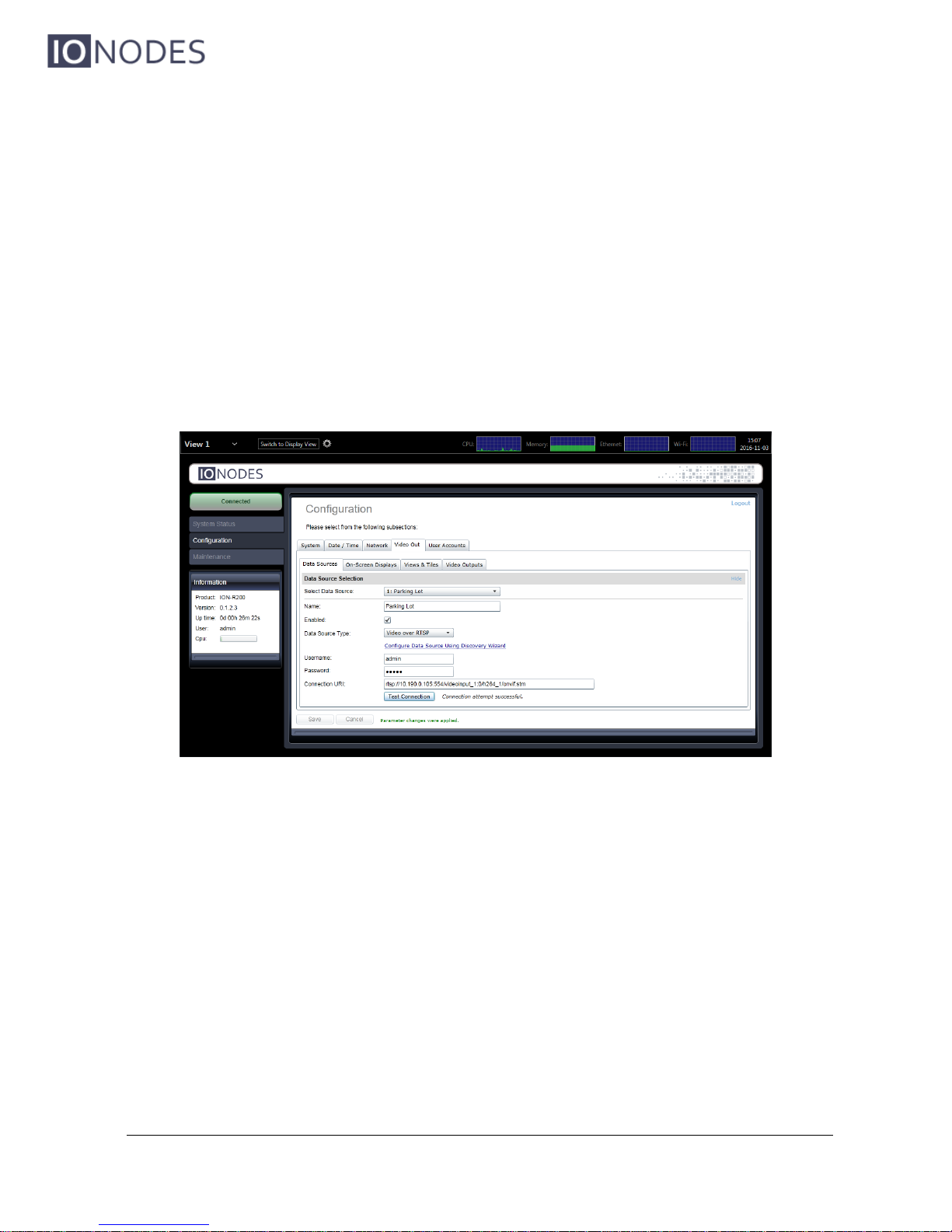
9.7.1.1 Testing a connection
Once the data source is fully configured and saved, press the Test Connection button to test
the connection.
Possible results are:
Connection attempt successful.
No error was reported while testing the connection.
Connection attempt timed out.
Tried to connect to the camera but got no answer. The camera may be temporarily
offline, else it is unreachable.
Page 31
ION-R200 – User manual
Page 31 of 49
Connection attempt refused by remote.
The connection to the camera was established, but the camera refused the
username/password provided.
Connection established, but unable to start video stream.
The connection to the camera was established, but the video stream could not be
started. The connection URI may not point to a valid video stream in the camera. This
can also occur if the camera has reached a connection or streaming limit due to other
third-party connections.
Invalid connection URI or internal error, connection attempt impossible.
The connection URI is malformed or incomplete.
9.7.2 Displaying a Data Source
Now that we have configured an RTSP video data source, the next step is to display it. In the
Configuration page, select the Video Out tab, then the Views & Tiles sub-tab.
Views determine how data sources are grouped and displayed. For example, by default each
view displays up to 4 data sources in a 2x2 layout. How to configure views will be discussed in
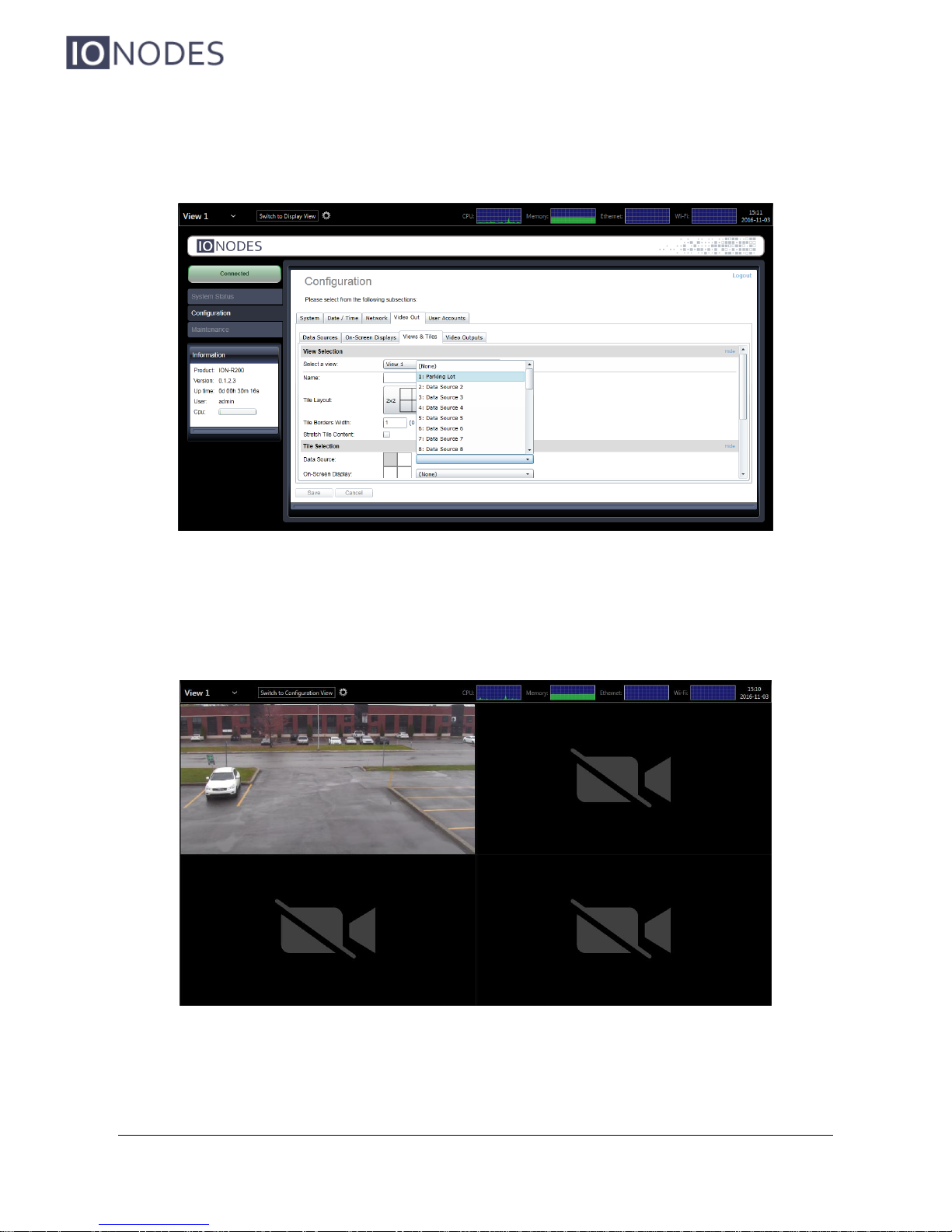
full details in section 9.9. For now, scroll down to the Tile Selection section. Each tile is
identified by its position in the currently selected layout.
Page 32
ION-R200 – User manual
Page 32 of 49
For the top left tile, click on the Data Source field and select our newly configured video data
source. Click on Save at the bottom to apply the change.
If you are configuring the ION-R200 from your computer through the device’s web interface, the
video is now displayed. If you are configuring the ION-R200 locally, click on Switch to Display
View at the top of the screen to view the video.
Page 33
ION-R200 – User manual
Page 33 of 49
9.7.3 On-Screen Displays
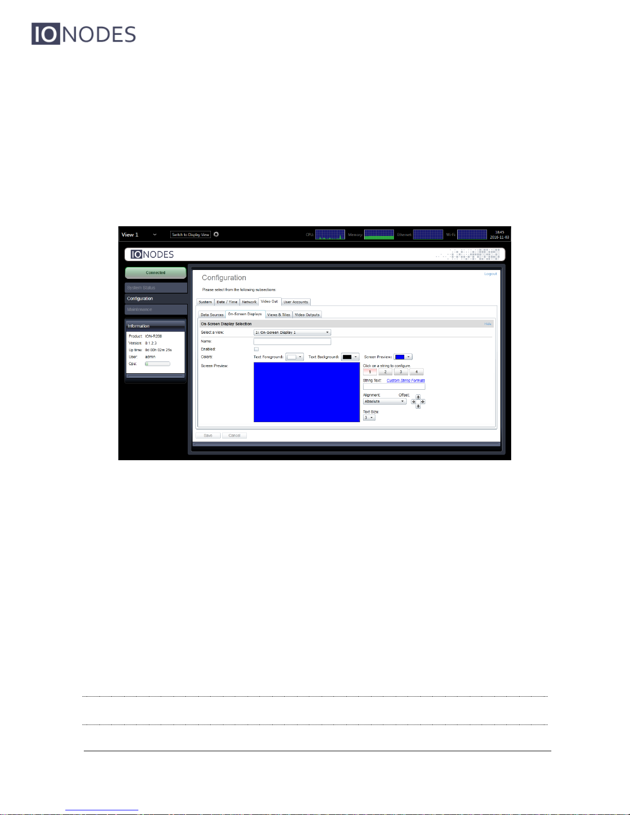
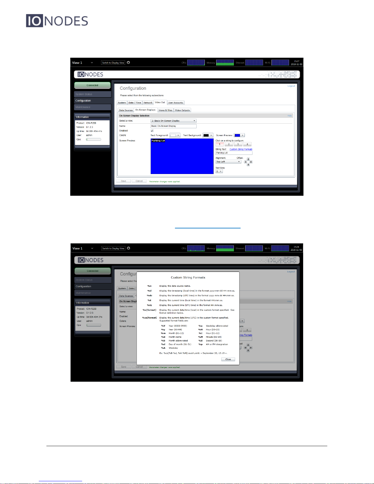
In the Configuration page, select the Video Out tab, then the On-Screen Displays sub-tab.
Screen Preview is a visual representation of the area where the OSD will be displayed. As you
configure the OSD, the preview will be automatically updated. Each OSD can display up to 4
strings of text, located as you wish over the video.
Click on Text Foreground to select the color of the OSD text. In the same fashion, click on
Text Background to select the background color for the OSD text.
On the right side of the preview is where you configure each OSD string. Click on the button 1
to configure the first OSD string. In String Text, type in the text to display. Alignment lets you
select where to anchor the text (ex: top left corner). Use the Offset arrows if you want to move
the text around that anchor. Finally, Text Size lets you select how big to display the text.
Ton configure other OSD strings, click on 2, 3 or 4 and set the appropriate text, alignment and
size.
Note: The ION-R200 provides a wide range of possible text sizes to ensure readability on a
wide variety of display sizes with resolutions from HD-720 all the way to 4K.
Page 34
ION-R200 – User manual
Page 34 of 49
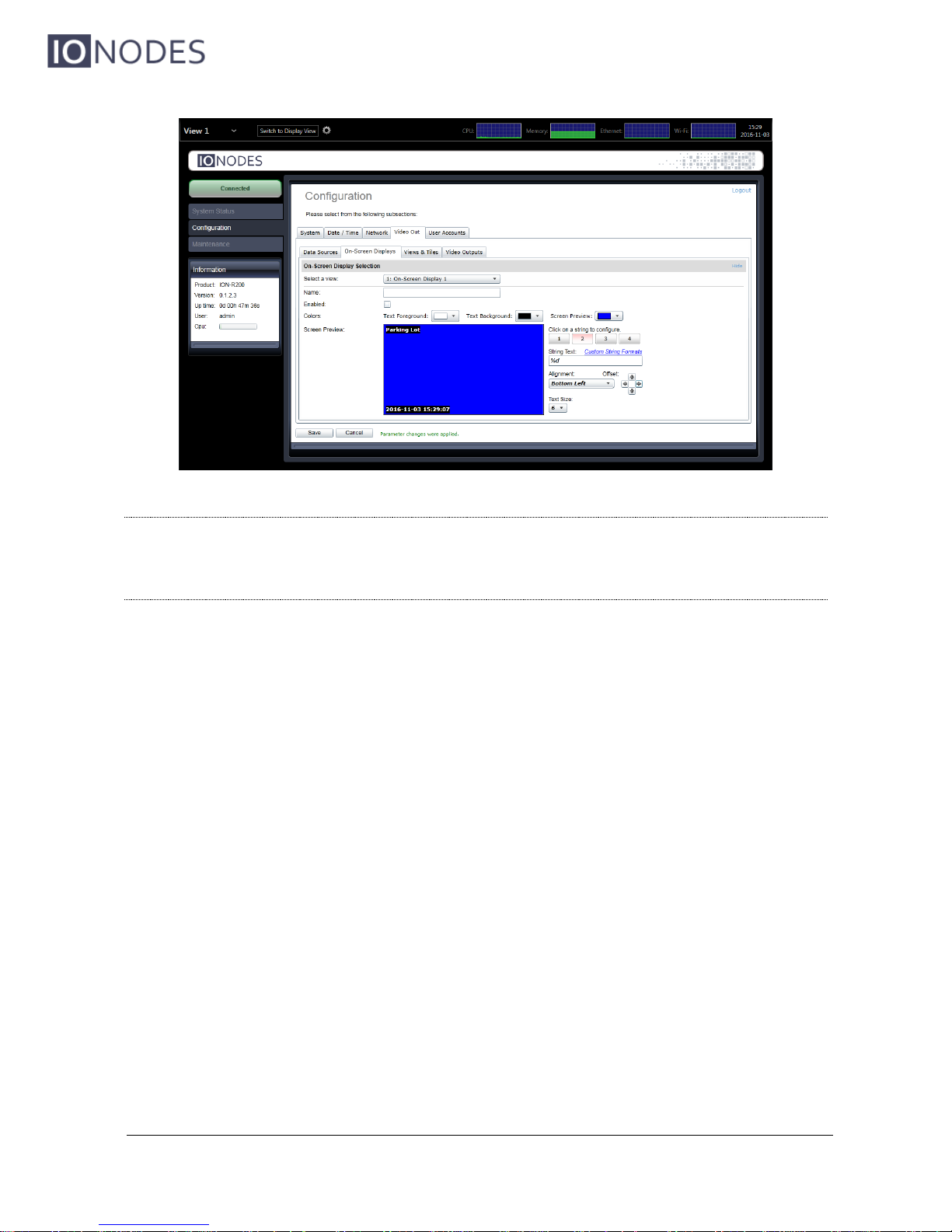
The ION-R200 supports a list of custom OSD strings to display dynamic information (ex: the
camera name or the current time). Click on Custom String Formats to see the complete list.
Page 35
ION-R200 – User manual
Page 35 of 49
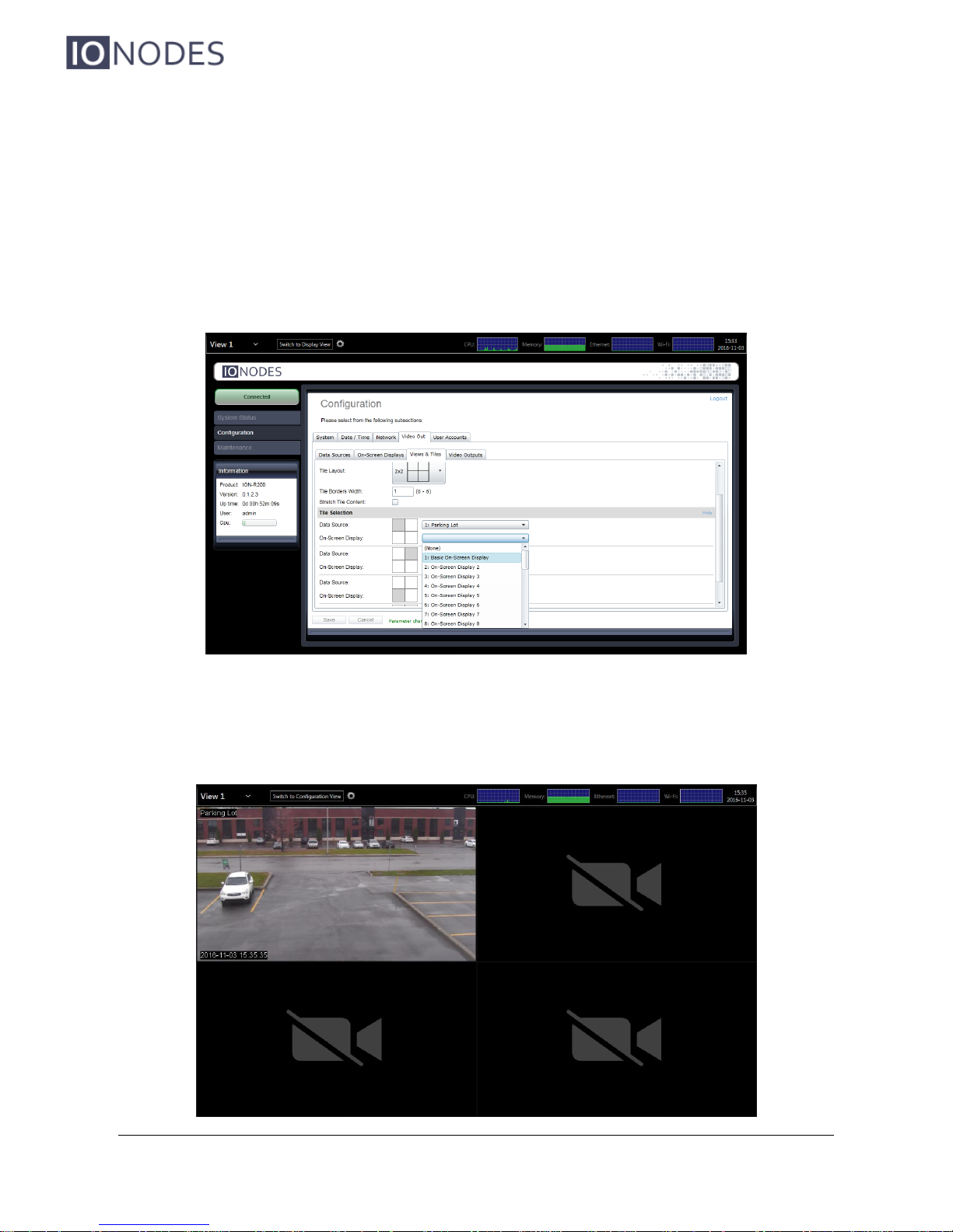
Note: Using custom OSD strings allows for greater flexibility. For example, displaying
“Parking Lot” in your OSD makes sense only for the camera pointed at the parking
lot. Instead, using “%n” (data source name) allows to create one OSD and display it
over all your video streams.
Page 36
ION-R200 – User manual
Page 36 of 49
9.7.4 Displaying an On-Screen Display
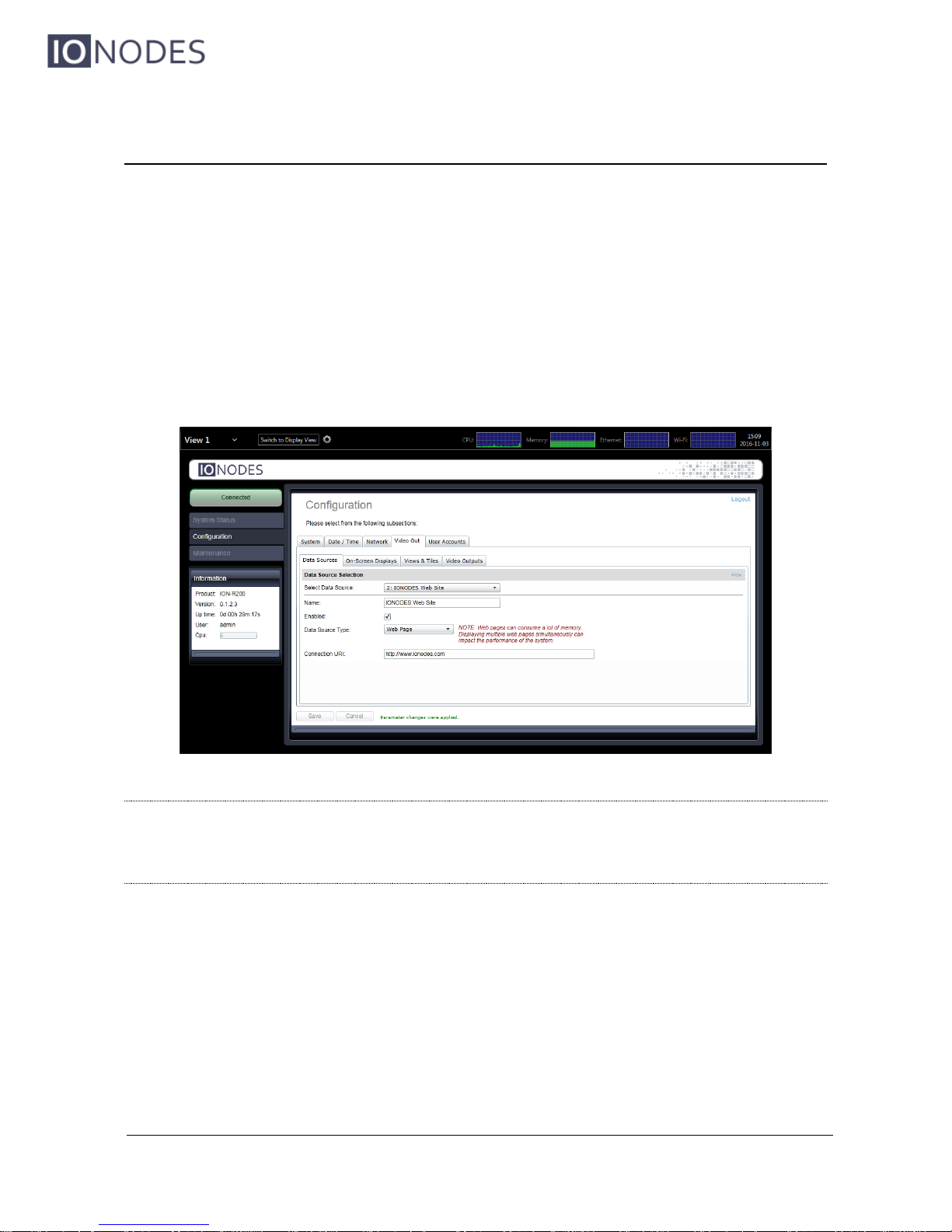
In the Configuration page, select the Video Out tab, then the Views & Tiles sub-tab. Scroll
down to the Tile Selection section.
For the top left tile, click on the On-Screen Display field and select our newly configured OSD.
Click on Save at the bottom to apply the change.
If you are configuring the ION-R200 from your computer through the device’s web interface, the
OSD is now displayed over the video. If you are configuring the ION-R200 locally, click on
Switch to Display View at the top of the screen.
Page 37
ION-R200 – User manual
Page 37 of 49
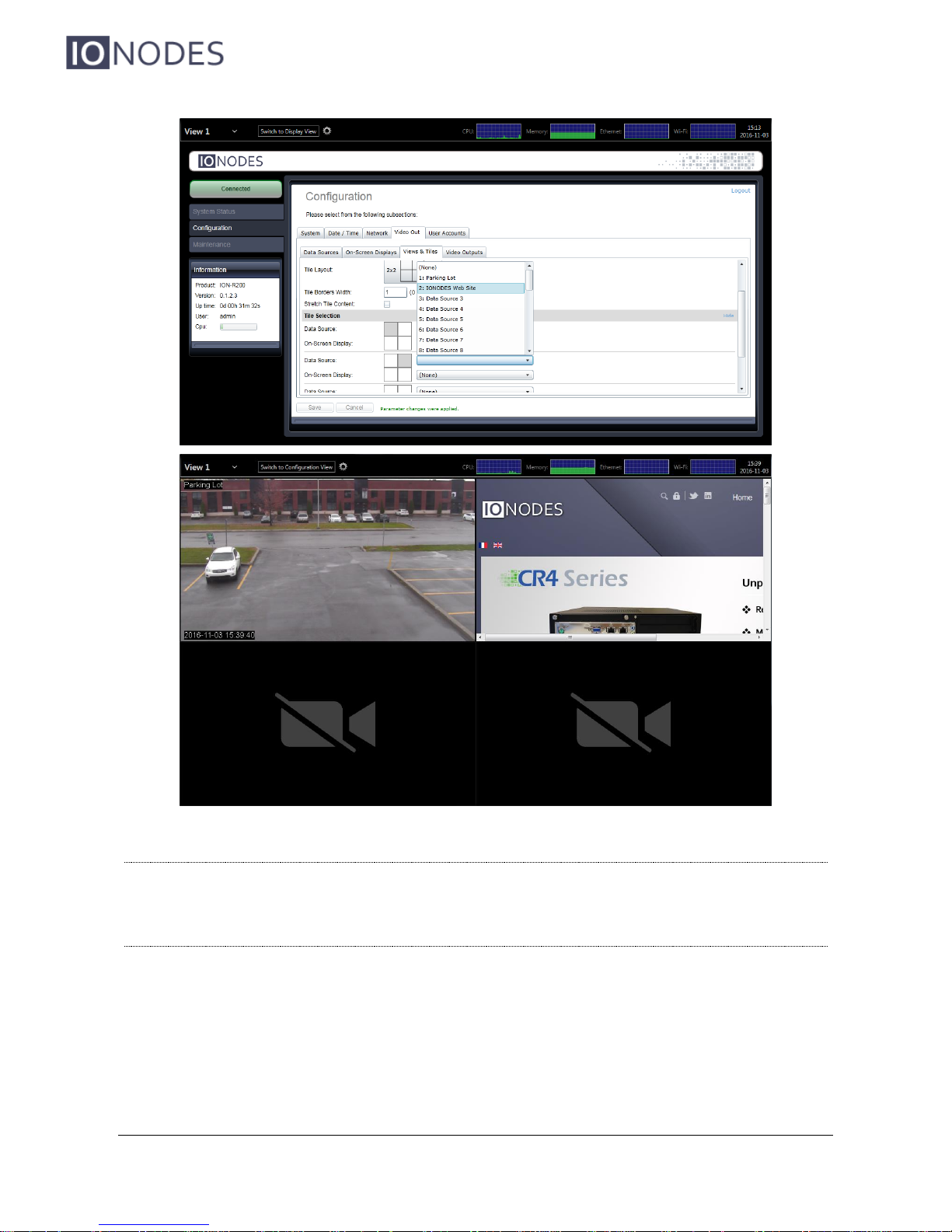
9.8 Configuring Web Connections
In the Configuration page, select the Video Out tab, then the Data Sources sub-tab. After
that, select an unused data source to configure. To configure a web connection, set Data
Source Type to Web Page.
Type in the address of the web page in Connection URI. Type in a name (optional) for the data
source, check Enabled to enable this data source and press Save at the bottom to save the new
configuration.
Note: The ION-R200 connects to a web page ONLY when that web page is displayed.
Enabling a data source indicates that the ION-R200 can establish this connection
when needed, not that it needs to do so right away. Disabling a data source prevents the ION-R200 from connecting to the web page for any reason.
To display the web page, we need to add it to a view. In the Configuration page, select the
Video Out tab, then the Views & Tiles sub-tab. Scroll down to the Tile Selection section.
For the top right tile, click on the Data Source field and select our newly configured web page
data source. Click on Save at the bottom to apply the change.
Page 38
ION-R200 – User manual
Page 38 of 49
Warning: Modern web pages are often filled with highly dynamic media content. Displaying such
content require a lot of resources. Displaying multiple web pages WILL affect the video
decoding performance of the ION-R200.
Page 39
ION-R200 – User manual
Page 39 of 49
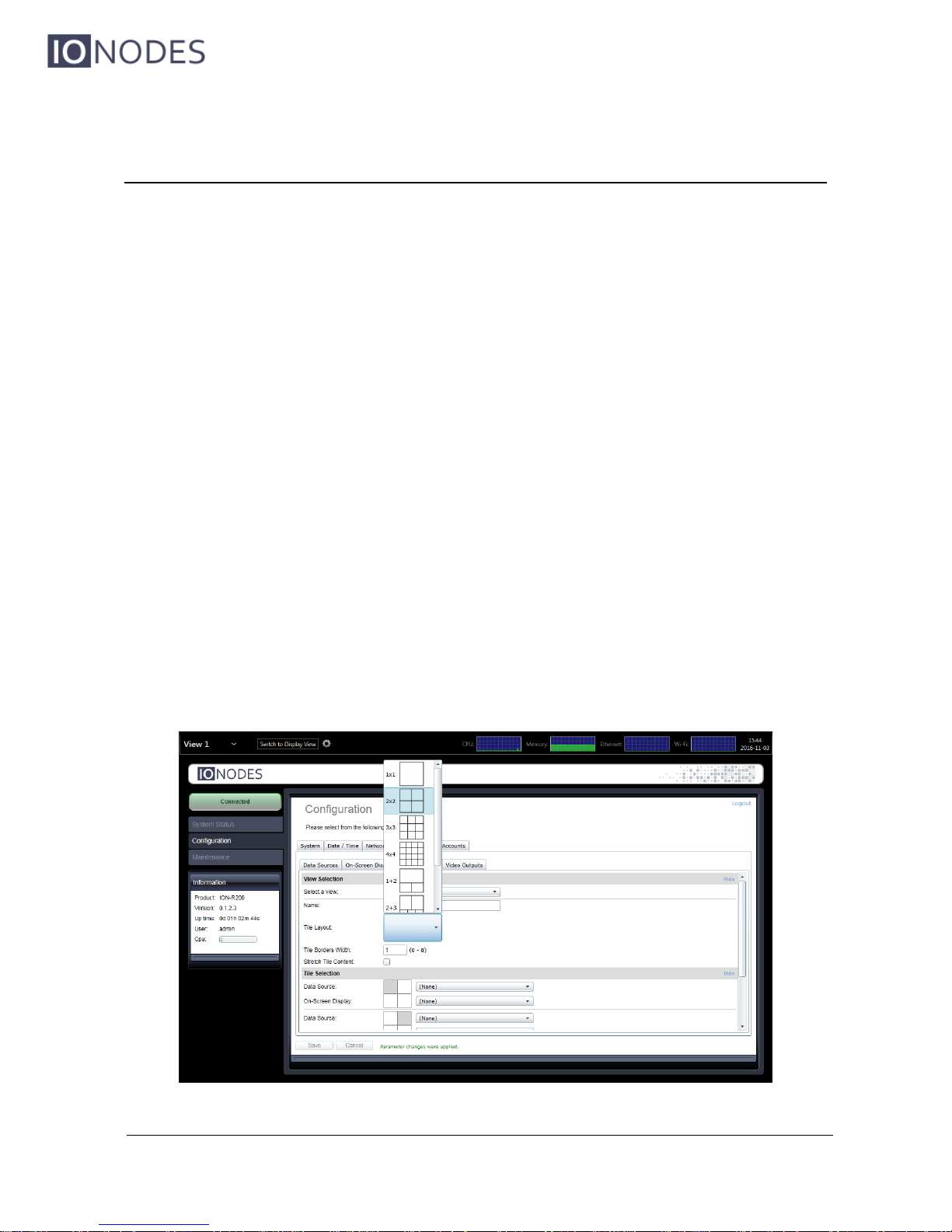
9.9 Configuring Views
In the Configuration page, select the Video Out tab, then the Views & Tiles sub-tab.
Views have the following configuration:
Name
User friendly name. Also displayed in the view selector in the top-left corner of the
screen.
Tile Layout
Views display content in one or more tiles. The tile layout dictates how many tiles to
display as well as how to organize these tiles.
Tile Border Width
Determines the width of the borders around each tile. A value of 0 means that no border
will be shown.
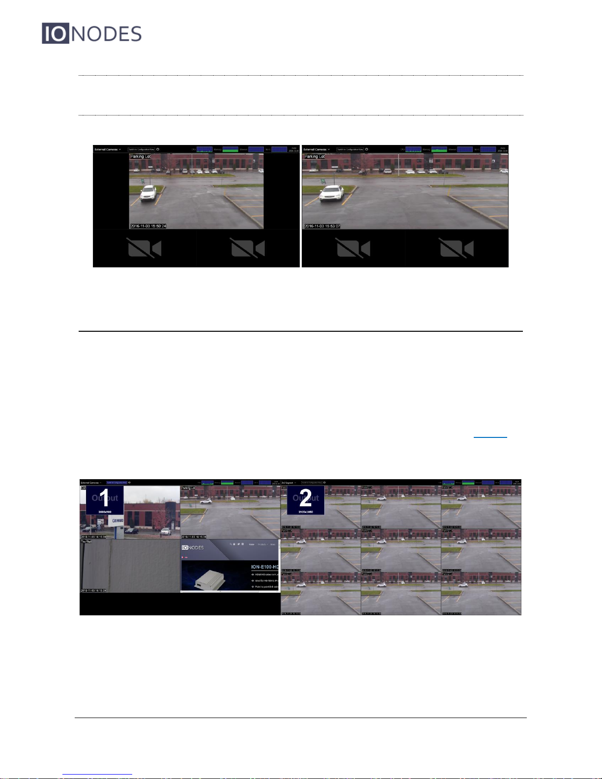
Stretch Tile Content
When the aspect ratio of a video stream does not match the aspect ratio of the tile
displaying it, this setting determine whether the video is stretched to fill the entire tile or
scaled to fit inside.
Page 40
ION-R200 – User manual
Page 40 of 49
Note: Stretching the content of a video tile can visibly deform the video, as shown in the
images below. Web pages simply adjust their layout based on the available space,
so they are generally not affected in the same way.
9.10 Configuring Video Outputs
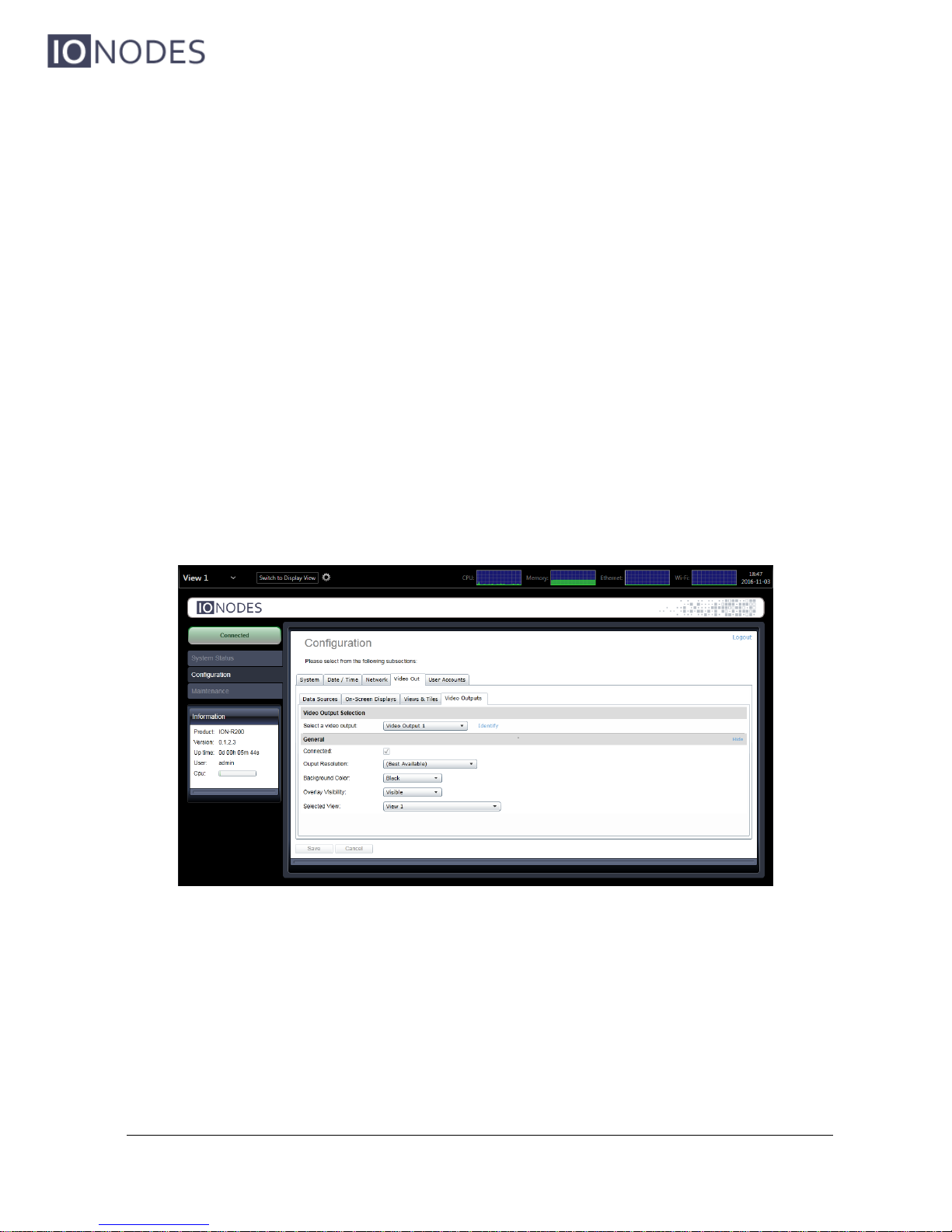
In the Configuration page, select the Video Out tab, then the Video Outputs sub-tab.
When a single display is connected to the ION-R200, that display is always referred to as
Display Output 1 regardless of the connector (HDMI or Mini DisplayPort) the display is
connected to. If there are two displays connected to the ION-R200, click on Identify to
determine which is Display Output 1 and which is Display Output 2.
Page 41
ION-R200 – User manual
Page 41 of 49
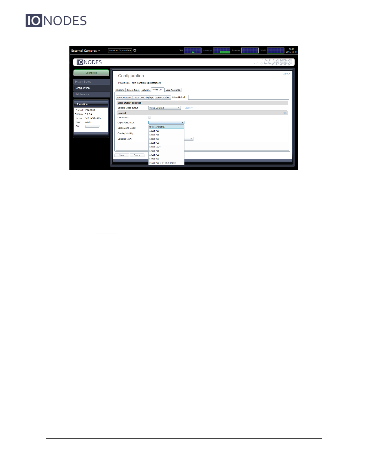
The configuration of each display output is as follows:
Connected (read only)
Indicates whether the display output is connected to a physical display.
Output Resolution
Determines the display resolution to use for this output. See below for details.
Background color
Determines the background color for empty tiles.
Overlay Visibility
The overlay is the utility bar at the top of the screen. The overlay can be displayed at all
times or it can automatically hide itself after being used. When auto-hidden, moving the
mouse to the top of the screen shows (temporarily) the overlay.
Selected View
Selects the view to display on this output. Changing this value is the equivalent of
selecting a view in the view selector in the top-left corner of the screen.
By default, display outputs are configured to automatically select the best resolution supported
by the TV or monitor. In most cases, this is the desired behavior. If you want to use a different
resolution, click on Output Resolution to display the list of supported resolutions.
Page 42
ION-R200 – User manual
Page 42 of 49
Note: If the ION-R200 is connected to two displays and you disconnect Display Output 1,
the other display automatically becomes Display Output 1. Display Output 2 is then
considered disconnected. A common mistake is to try to configure a disconnected
output.
Use the Identify feature to make sure you are configuring the right display.
If you disconnect a display, the ION-R200 remembers the selected output resolution in case the
display was disconnected by mistake. If you reconnect the same display, the output resolution
remains unchanged. If you connect a different display in its place, the new display may not
support the same set of possible output resolutions. In that case, the output resolution
automatically reverts to Best Available to prevent any compatibility issues with the new
connected display.
Page 43
ION-R200 – User manual
Page 43 of 49
10 Performing a Firmware Update
This section describes how to update your ION-R200 to newer firmware versions from the web
interface.
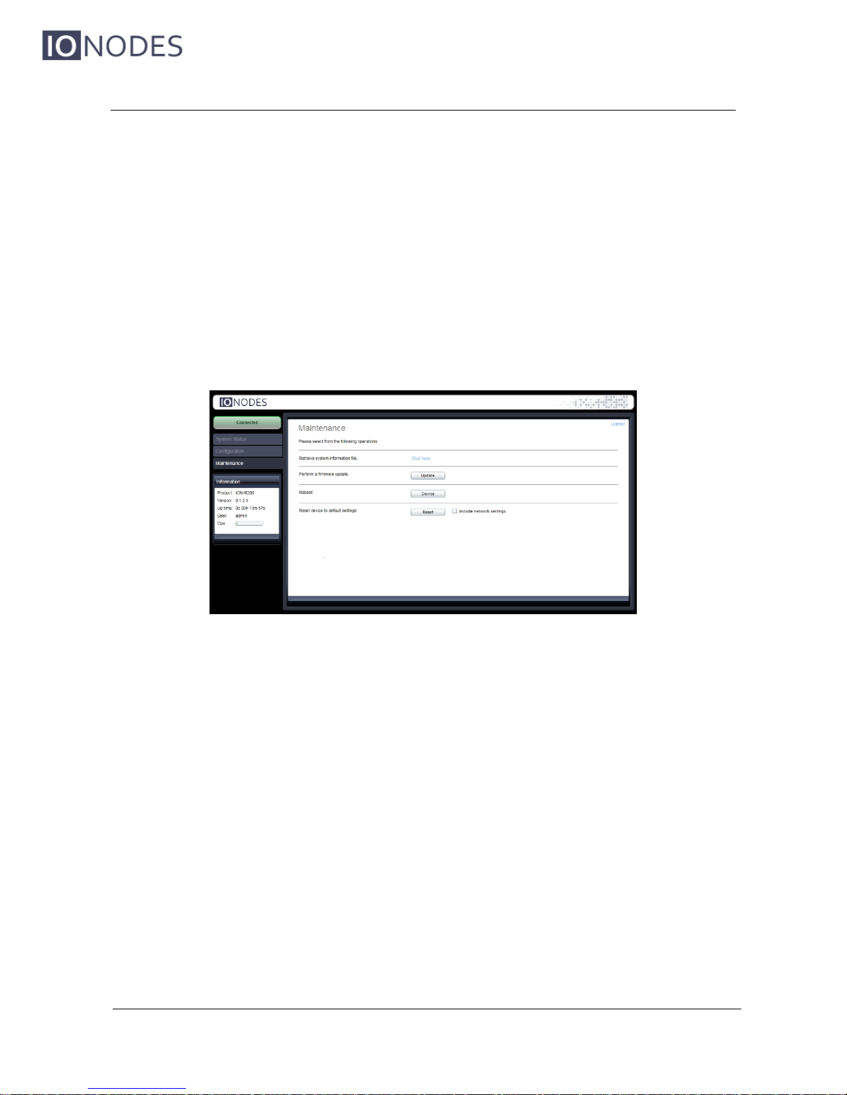
1. On the device, switch to configuration view OR navigate to your device’s web interface.
2. If not currently logged in, log in using an administrator account’s credentials.
3. Click on the Maintenance tab.
4. Click on the Update button. You will be asked for the firmware update file; please select
the .iof file which was provided by IONODES.
5. You will see the following messages indicating the status of the update:
o Firmware upload in progress... (100%)
o Firmware uploaded. Saving to internal storage... (0%)
o Validating and decompressing firmware... (0%)
o Firmware ready for installation. Rebooting device... (0%)
Web page will disconnect and the device will reboot.
Once the device has rebooted, return to the configuration view. If you
are performing the firmware update remotely, the web interface automatically reconnects.
o Testing firmware stability... (26%)
Lasts 120 seconds.
o Firmware update complete. (100%)
Page 44
ION-R200 – User manual
Page 44 of 49
10.1 Batch Firmware Update
This section describes how to perform a batch update of multiple ION-R200 devices to newer
firmware versions from the ION Configuration Tool (ICT).
The batch firmware update works by starting a firmware update session. Only one session at
time is allowed and only 20 devices can be selected by session.
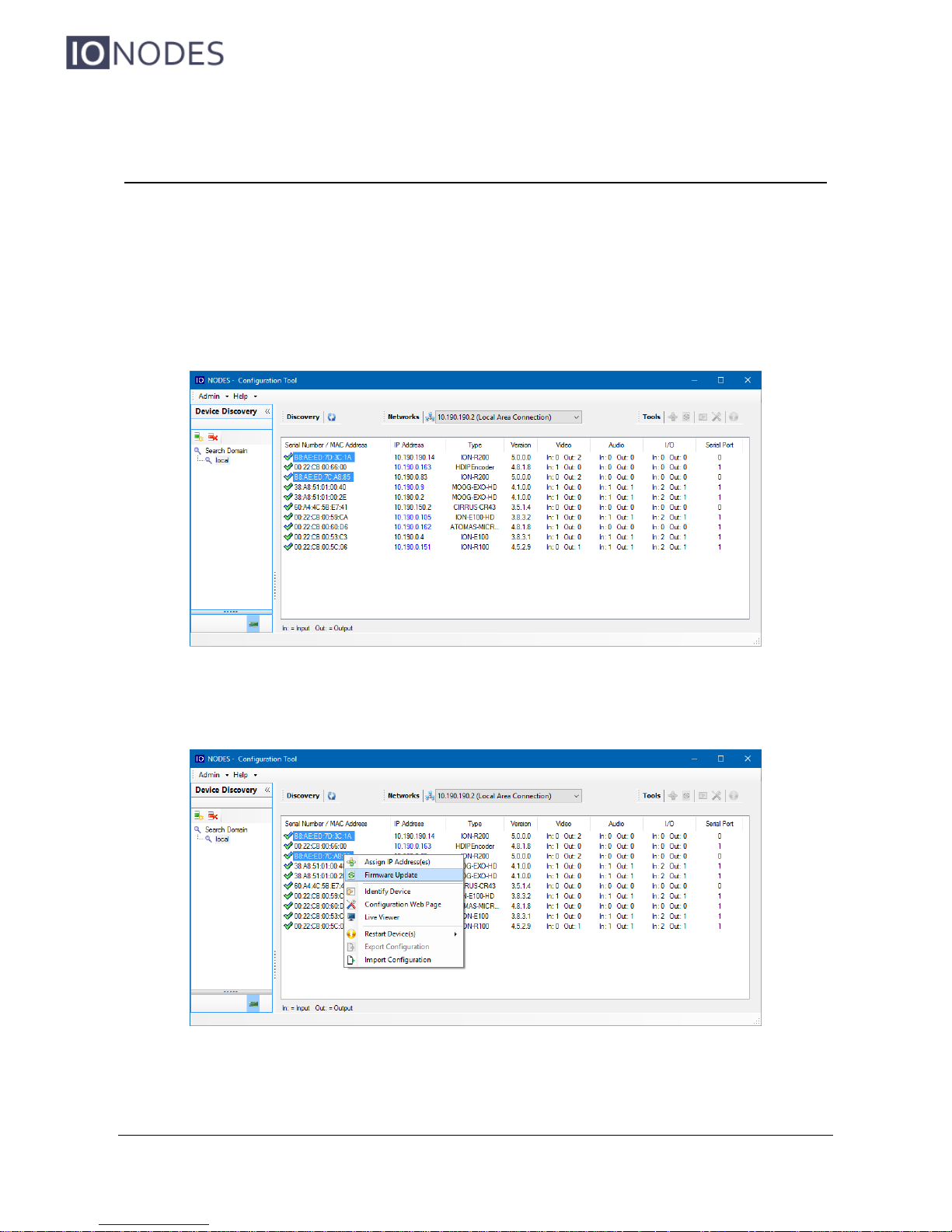
From the ICT, select one or more ION-R200 devices.
By using the right mouse button on the selected devices, choose the “Firmware Update” menu
option.
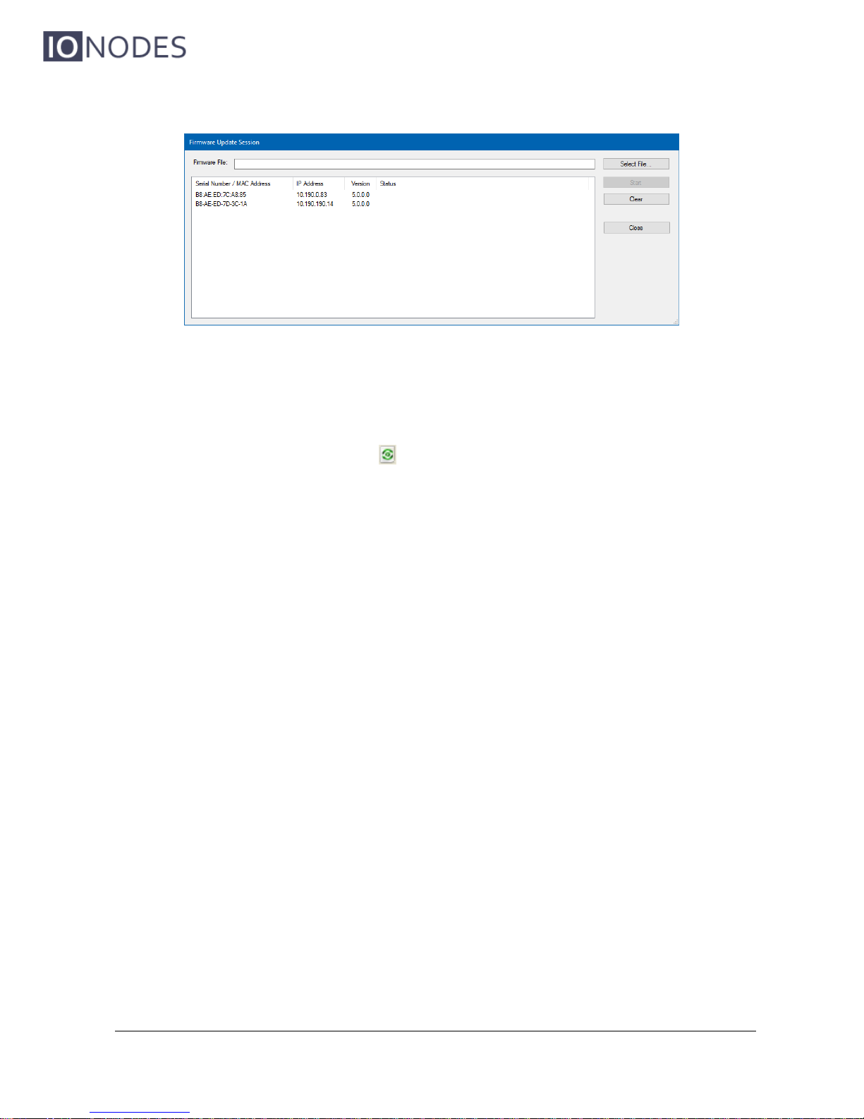
To start a firmware update session, choose the “.iof” file corresponding to the new firmware by
clicking to the “Select File …” button. Once selected, click to the “Start” button.
Page 45
ION-R200 – User manual
Page 45 of 49
Once started, the “Firmware Update Session” window shows the progress of the firmware
update. This window can be closed at any moment without losing the current session.
If closed, the progress of the current session can be followed by reopening the “Firmware
Update Session” window by clicking the button from the “Tools” toolbar.
Once done, clear the current session from the “Firmware Update Session” window and restart a
new session if needed.
Page 46
ION-R200 – User manual
Page 46 of 49
11 Diagnostics
11.1 View Stream Details
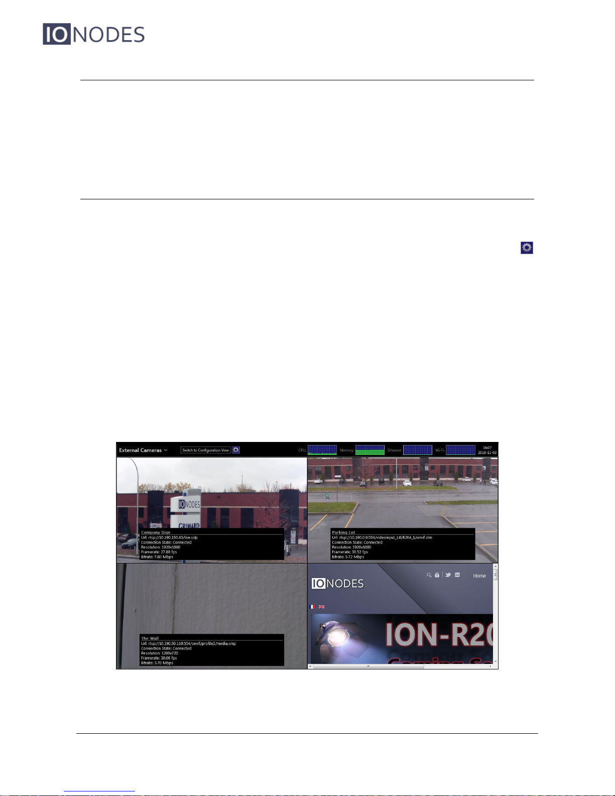
In order to help diagnose connectivity or performance problems, the ION-R200 can display live
details about the video displayed in each tile. To display the stream details, click on the
button at the top of the screen.
The stream details include:
The name of the data source
The connection URI
The current connection status
The video stream resolution (not the size of the tile the video is playing in)
The video stream framerate
The video stream bitrate
Page 47

ION-R200 – User manual
Page 47 of 49
11.2 Safe Mode
It is possible to configure the ION-R200 in such a way that there is just too much video to
decode. Whether it is due to the number of concurrent video streams or the combined bitrate of
all video streams being too high, in such scenarios the ION-R200 may run at maximum capacity
and it may not be enough to decode all the video. In such a scenario, the ION-R200 may
become increasingly unresponsive, thus preventing access the configuration of the device in
order to fix the problem.
It is also possible that a video stream from a third-party camera may not strictly follow the H.264
video encoding standard, causing problems in the ION-R200 while decoding the video stream.
For all scenarios where the device becomes uncooperative, the ION-R200 offers a solution in
the form of safe mode. Safe mode is a special mode of operation where all data sources are
forcibly disabled. The device therefore no longer decodes any video, giving you easy access to
the configuration of the device to fix the issue before returning to the normal mode of operation.
Safe mode is enabled during the boot-up of the device. It requires a keyboard to be connected
to the device. While the ION-R200 is booting up, wait for the device to reach the step shown in
the image below:
While the ION-R200 starts its system services, press and hold the LEFT SHIFT key and
RIGHT SHIFT key on the keyboard. When the device detects the key combination, it
acknowledges the switch to safe mode operation as shown below:
Note: It takes only a few seconds for the ION-R200 to start the system services and safe
mode can be enabled only during that step of the boot-up sequence. If the device
Page 48

ION-R200 – User manual
Page 48 of 49
finishes booting up before you press the key combination, you can simply shut down
and restart the device and try again.
Once you fix the configuration of the ION-R200, you need to restart the device to return to its
normal mode of operation.
Page 49
ION-R200 – User manual
Page 49 of 49
Annex A – Statement Limited Warranty
The warranties provided by Ionodes Inc. (Ionodes) in this Statement of Limited Warranty apply only to
ION-R200 products purchased from an authorized Ionodes Inc. (Ionodes) Reseller, Integrator or
Distributor and returned from European, Asian or North American countries, and excludes all Latin
American countries. The term "ION-R200" means an ION-R200 module, any module upgrade, or
accessories, or any combination of them. The term "ION-R200" does not include any software
programs, whether pre–loaded with the ION-R200, installed subsequently or otherwise which are
covered by a separate Limited Warranty. Nothing in this Statement of Warranty affects any statutory
rights of purchaser that cannot be waived or limited by contract. If you have any questions regarding
this Limited Warranty, contact Ionodes Inc. and its resellers. The Warranty period for the ION-R200 is
3 years from date of billing for the ION-R200 product.
The Ionodes Warranty for ION-R200
Ionodes warrants that each ION-R200 is free from defects in materials and workmanship, and conforms to the ION-R200 Official Published Specifications (See http://www.ionodes.com for details).
The warranty period for an ION-R200 is a specified, fixed period commencing on date of billing by
Ionodes for the Product. If a valid proof of billing cannot be found, the warranty may be void by Ionodes Inc. or measured from the date the ION-R200 has shipped from a Ionodes Depot center based
on its serial number.
If, during the warranty period, the ION-R200 is not in good working order, Ionodes will, at its option,
repair or replace it at no additional charge, except as is set forth below.
In some cases, the replacement product may not be new and may have been previously installed.
Regardless of the replacement product used, Ionodes’ appropriate warranty terms apply.
In case Ionodes or your reseller are unable to repair an Ionodes ION-R200, you can alternatively ask
for a partial refund as far as justified by the reduced value of the unrepaired ION-R200 or ask for a
cancellation of the respective agreement for such ION-R200 and get your money refunded.
Extent of Warranty
The warranty does not cover the repair or exchange of an ION-R200 resulting from misuse, accident,
modification, unsuitable physical or operating environment, improper maintenance by the end user, or
failure caused by a product for which Ionodes is not responsible. The warranty is voided by removal
or alteration of ION-R200 or parts identification labels.
THESE WARRANTIES ARE YOUR EXCLUSIVE WARRANTIES AND REPLACE ALL OTHER
WARRANTIES OR CONDITIONS, EXPRESS OR IMPLIED, INCLUDING, BUT NOT LIMITED TO,
THE IMPLIED WARRANTIES OR CONDITIONS OF MERCHANTABILITY AND FITNESS FOR A
PARTICULAR PURPOSE.
Items Not Covered by Warranty
Ionodes does not warrant uninterrupted or error–free operation of an ION-R200. Any technical or
other support provided for an ION-R200 under warranty, such as assistance via telephone with "how–
to" questions and those regarding ION-R200 set–up and installation, will be provided WITHOUT
WARRANTIES OF ANY KIND.
 Loading...