

Page 1
USER MANUAL
GATEWAY MEDIUM
Data connector for indoor and outdoor use
Ceruus Oy, ioLiving
Technical support:
1 (13)
ioliving.com
helpdesk@ioliving.com
Data connector for indoor and outdoor use. Connected to the
Internet via a network cable (included) or wireless network.
In addition, an HDMI display and a USB keyboard are
required for connecting to a wireless network. The device is
used for continuous transfer of measured data to the ioLiving
cloud service.
Protection: IP56, Protection against water jets
Temperature: -20 °C – +60 °C
LoRa frequency: 871.5 MHz
Gateway Medium
Page 2

USER MANUAL
GATEWAY MEDIUM
Data connector for indoor and outdoor use
Ceruus Oy, ioLiving
Technical support:
2 (13)
ioliving.com
helpdesk@ioliving.com
Table of contents
Gateway Medium ............................................................................................................................................................................. 1
CONNECTING GATEWAY TO THE INTERNET ..................................................................................................................... 3
Start the installation................................................................................................................................................................ 3
WIRED NETWORK CONFIGURATION ................................................................................................................................ 3
Installation .................................................................................................................................................................................. 3
Establishing a connection ..................................................................................................................................................... 3
WIRELESS NETWORK CONFIGURATION (WLAN, WiFi) ............................................................................................ 4
Installation .................................................................................................................................................................................. 4
Establishing a connection ..................................................................................................................................................... 5
Verify the functionality of the wireless network. ........................................................................................................... 7
Finally verify the server connection functionality. ......................................................................................................... 8
GATEWAY LED SIGNAL DESCRIPTION AND TROUBLESHOOTING ....................................................................... 10
LED symbol descriptions .................................................................................................................................................... 10
Possible wireless network configuration problems: .................................................................................................. 11
GATEWAY ACTIVATION IN IOLIVING SERVICE ............................................................................................................... 12
Page 3
USER MANUAL
GATEWAY MEDIUM
Data connector for indoor and outdoor use
Ceruus Oy, ioLiving
Technical support:
3 (13)
ioliving.com
helpdesk@ioliving.com
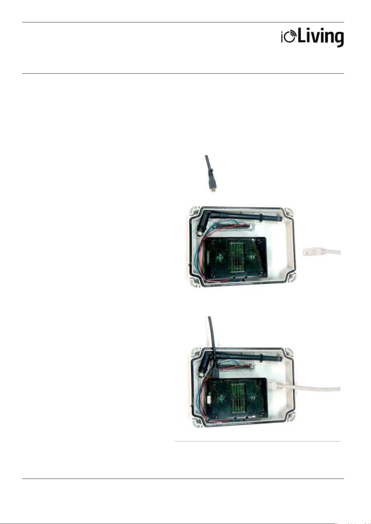
Installation
If a wired network (i.e. Ethernet,
LAN) connection is available, it
can be used for Gateway’s data
transmission. Connect powered
USB connector and network
cable to establish the wired
connection.
Figure 1:
Gateway Medium and
components for wired network
connection.
Establishing a connection
After installing the Gateway as
described, it connects
automatically to the internet and
ioLiving data server.
Close the cover with locking
screws and the Gateway is ready
to use. Ensure that the Gateway
connects to the ioLiving server by
checking the signal LED’s status
in the cover.
Figure 2:
Gateway Medium connected to
wired network.
USB power cable
Network cable
CONNECTING GATEWAY TO THE INTERNET
Start the installation
Open the four (4) locking screws and remove the Gateway’s front cover.
WIRED NETWORK CONFIGURATION
Page 4
USER MANUAL
GATEWAY MEDIUM
Data connector for indoor and outdoor use
Ceruus Oy, ioLiving
Technical support:
4 (13)
ioliving.com
helpdesk@ioliving.com
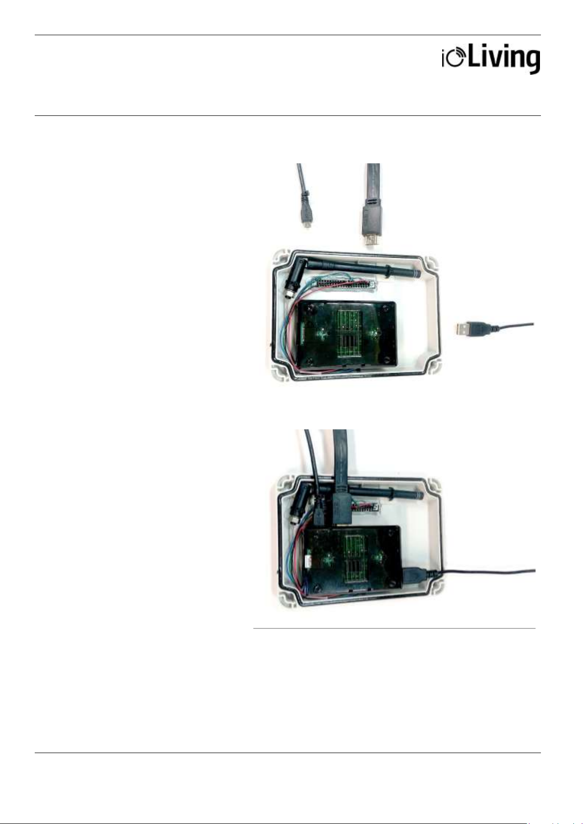
Installation
To configure the wireless
network (i.e. Wi-Fi, WLAN)
connection: Connect HDMI
display, USB-keyboard and
USB power cable as
described following.
Figure 1.
Gateway Medium and
required components for
wireless network
configuration.
Figure 2.
Gateway Medium ready for
wireless network
configuration.
USB
power cable
USB keyboard
HDMI display cable
WIRELESS NETWORK CONFIGURATION (WLAN, WiFi)
Page 5

USER MANUAL
GATEWAY MEDIUM
Data connector for indoor and outdoor use
Ceruus Oy, ioLiving
Technical support:
5 (13)
ioliving.com
helpdesk@ioliving.com
Establishing a connection
After connecting the
Gateway Medium as
described and powering it
with USB cable, the wireless
network configuration can be
started.
Figure 3.
Select ”Configuration” and
”OK” with <arrow keys>
and press <Enter>.
Figure 4.
Select “Configure wifi” and
“OK” with <arrow keys>
and press <Enter>.
Figure 5.
A list of available wireless
networks appears.
Select the wanted network
with the <arrow keys>. Pay
attention to network’s
encryption (third column),
which is usually ”WPA2”.
Enter the network setup
with <right arrow key>.
Page 6

USER MANUAL
GATEWAY MEDIUM
Data connector for indoor and outdoor use
Ceruus Oy, ioLiving
Technical support:
6 (13)
ioliving.com
helpdesk@ioliving.com
Figure 6.
Network setup window.
The cursor can be moved
with the <arrow keys>.
Selections can be made by
pressing <Enter> when the
cursor is on wanted setting.
The selected setting
indicates ”X”.
Select “Automatically
connect to this network” to
ease the connection in the
future.
If the network requires encryption, select “Use encryption” and then press
<Enter> on the next line to open the selection. Usually the network
authentication requires a password and therefore the network encryption is
WPA 1/2 (Passphrase)”. Enter the password for the wireless network.
Save the settings by pressing <F10>. Note that the encryption of the wireless
network can differ from “WPA 1/2 (Passphrase)”.
Figure 7.
After the successful
connection, network’s name
turns green on the list.
If the automatic connection doesn’t work for some reason, it is possible to
initiate the connection by pressing <shift> + <C> (there’s a couple seconds
delay in the software). The connection status appears at the bottom of the
window. While selecting the network, the first column shows the strength of
the signal in percentage (max signal strength is 100%). If the signal strength
is low, relocating the Gateway may improve the connection strength.
Exit the network setup by pressing <Q>.
Page 7

USER MANUAL
GATEWAY MEDIUM
Data connector for indoor and outdoor use
Ceruus Oy, ioLiving
Technical support:
7 (13)
ioliving.com
helpdesk@ioliving.com
Verify the functionality of the
wireless network.
Figure 8.
In the main menu select
”Information” and ”OK” with
<arrow keys> and press
<Enter>.
Figure 9.
Select ”Show IP address”
and ”OK” with <arrow keys>
and press <Enter>.
Figure 10.
If the wireless network
connection is OK, the IP
address window appears
Page 8

USER MANUAL
GATEWAY MEDIUM
Data connector for indoor and outdoor use
Ceruus Oy, ioLiving
Technical support:
8 (13)
ioliving.com
helpdesk@ioliving.com
Finally verify the server
connection functionality.
Figure 11.
In the main menu select
”Information” and ”OK”
with <arrow keys> and press
<Enter>.
Figure 12.
Select ”Server connection”
and ”OK” with <arrow keys>
and press <Enter>.
Figure 13.
If the server connection is
OK, a notification window
with text “Server connection
OK” appears
Page 9

USER MANUAL
GATEWAY MEDIUM
Data connector for indoor and outdoor use
Ceruus Oy, ioLiving
Technical support:
9 (13)
ioliving.com
helpdesk@ioliving.com
After verifying the server connection, the display and keyboard can be disconnected from the Gateway. Close
the cover with locking screws and leave the Gateway online. Since the automated network connection is
selected and stored in the settings, it is also possible to power off the Gateway. It will connect automatically to
the server when the power is on again and the configured wireless network is available.
Page 10

USER MANUAL
GATEWAY MEDIUM
Data connector for indoor and outdoor use
Ceruus Oy, ioLiving
Technical support:
10 (13)
ioliving.com
helpdesk@ioliving.com
Figure 1.
There are seven signal LEDs in the Gateway device.
Table 1:
LED symbol descriptions
Gateway status LED
Green blinking: The power is on and the device is operational.
Not blinking: The software has halted, reboot the device.
Initializing LED
Yellow blinking: The device has been recently turned on. When the device is ready (device
boot up and initialization may take few minutes) the LED turns off.
Constant red:
1. Reboot the Gateway.
2. Check the selected network’s connection with another device.
Bluetooth LED
Constant green: The device has detected Bluetooth devices within the range
LoRa LED
Constant green: The device has detected LoRa devices within the range.
Occassionally blinking blue: The LoRa signal has been received.
Wired network connection LED
Constant green: Wired connection is OK.
Constant red: No wired or wireless connection (Appears concurrently with wireless red LED) *
Wireless network connection LED
Constant green: Wireless connection is OK
*Constant red: No wired or wireless connection
(Appears concurrently with wired red LED)
ioLiving server LED
Constant green: Connection to ioLiving server is OK.
GATEWAY LED SIGNAL DESCRIPTION AND TROUBLESHOOTING
Page 11

USER MANUAL
GATEWAY MEDIUM
Data connector for indoor and outdoor use
Ceruus Oy, ioLiving
Technical support:
11 (13)
ioliving.com
helpdesk@ioliving.com
Constant red: No connection to ioLiving server:
1. Reboot the Gateway.
2. Check the network connection with another device.
3. Try again after longer period, the server may be down or overloaded.
4. Contact the device support..
If the both network LEDs are red there’s no active network connection at all. Check the desired
network configuration from the user’s guide chapter XXX.
Notice that the network connection can be either wired or wireless, not the both at the same
time.
It may take several minutes after the device boot up until the connection is established.
Possible wireless network configuration problems:
1. Black screen:
Check the monitor is switched on.
Check the monitor power cable is connected correctly.
Check the monitor’s signal cable is connected correctly.
2. No setup window on the screen:
Check the Gateway’s USB power cable is connected correctly.
Check the USB power cable is active.
3. The keyboard is not working.
Check the keyboard cable is connected correctly.
4. A command window appears:
Write “setup” and press <Enter> to start the setup.
Page 12

USER MANUAL
GATEWAY MEDIUM
Data connector for indoor and outdoor use
Ceruus Oy, ioLiving
Technical support:
12 (13)
ioliving.com
helpdesk@ioliving.com
To monitor Gateway’s
functionality and status, it must
be activated in the ioLiving
service.
Figure 1.
Gateway’s serial number can be
found in the sticker attached to
the casing.
1. Write down Gateway’s
serial number.
2. Sign in to the ioLiving service
portal www.ioliving.com
Login with your
credentials
Account
Gateway devices
3. Activate the Gateway with its
serial number.
Figure 2.
Gateway’s activation window.
GATEWAY ACTIVATION IN IOLIVING SERVICE
Page 13

USER MANUAL
GATEWAY MEDIUM
Data connector for indoor and outdoor use
Ceruus Oy, ioLiving
Technical support:
13 (13)
ioliving.com
helpdesk@ioliving.com
4. After the activation Gateway
status can be checked in the
ioLiving service by selecting:
Gateway devices
5. It is possible to activate
several Gateways under the
same account.
6. The notifications can be
turned on/off with just a click
of a mouse.
7. The device can be removed
from the account when
necessary.
Figure 3.
Gateway device’s status window.
 Loading...