

Page 1

1
Quick Start Guide
I/S Series SC Series
I/S 60, 85, 110, 130 and 100 System SC-40 & -48
Ioline SmarTrac™
Page 2

2
User Notice
Trademarks
Ioline and SmarTrac are trademarks of Ioline Corporation. Other product names, logos, designs, titles, words or
phrases mentioned within this publication may be trademarks, service marks, or trade names of Ioline Corporation or
other entities and may be registered in certain jurisdictions including internationally.
Ioline Disclaimer
IOLINE CORPORATION PROVIDES THIS MANUAL “AS IS” WITHOUT WARRANTY OF ANY KIND, EITHER
EXPRESS OR IMPLIED, INCLUDING BUT NOT LIMITED TO THE IMPLIED WARRANTIES OR CONDITIONS OR
MERCHANTABILITY OR FITNESS FOR A PARTICULAR PURPOSE. IN NO EVENT SHALL IOLINE, ITS DIRECTORS, OFFICERS, EMPLOYEES OR AGENTS BE LIABLE FOR ANY INDIRECT, SPECIAL, INCIDENTAL, OR
CONSEQUENTIAL DAMAGES (INCLUDING DAMAGES FOR LOSS OF PROFITS, LOSS OF BUSINESS, LOSS OF
USE OR DATA, INTERRUPTION OF BUSINESS AND THE LIKE), EVEN IF IOLINE HAS BEEN ADVISED OF THE
POSSIBILITY OF SUCH DAMAGES ARISING FROM ANY DEFECT OR ERROR IN THIS MANUAL OR PRODUCT.
Limit of Liability Statement
It is the responsibility of the operator of the cutter to monitor the performance of the cutter and maintain it in proper
working condition by following the instructions in this User Guide. It is the responsibility of the operator of the cutter
to follow all safety precautions and warnings that are described in this User Guide. Ioline is not responsible for injuries that may occur as a result of unsafe operating procedures. Ioline is not responsible for substandard operational
performance as a result of failure to maintain the cutter as described in this User Guide.
© 1997-2005 Ioline Corporation. All rights reserved. This manual may not be copied, photocopied, reproduced, translated, transmitted or converted to any electronic or machine-readable form in whole or in part without prior written
approval of Ioline Corporation.
Service and Support
If you require assistance with an Ioline product, your local Ioline dealer or authorized service center is ready to help.
Support information is also available 24/7 on the Ioline Web site—or you may contact Ioline directly:
Ioline Corporation
14140 NE 200th Street
Woodinville, Washington 98072 U.S.A.
Ioline Customer Service Department
Monday through Friday
7:00 A.M. - 5:00 P.M. U.S. Pacic Time
Voice: 1.425.398.8282
Fax: 1.425.398.8383
support@ioline.com
www.ioline.com
Part Numbers: (Print) 106916 Rev. 8 • (File) 107109 Rev. 5
Page 3

Please read these safety guidelines before beginning operation of
the cutter. The cutter uses a very sharp blade when cutting. The
parts can move quickly. Always observe the following safety precautions:
n Do not allow the material to become suddenly taut between
the cutter and a roll of material during plotting. A service
loop of unrolled material is required for problem-free operation. Using the Autoloop function (enabled in the Control
Center) will create the required service loop by gently pulling
a set amount of material from the roll before cutting. Ioline
recommends using the Autoloop function when plotting on a
roll of material.
Safety &
Cautions
n Do not try to repair the machine without factory authorization.
Only qualied service personnel should attempt any disassembly or access to internal components. If external mechanical
adjustments are necessary, turn off the cutter and disconnect it
from all power sources (both the computer and the wall outlet).
n Be careful with hair, jewelry, or loose clothing near the cutter.
They can become caught in the mechanical parts.
n Never move the carriage by hand. Use the Arrow keys and let
the machine do it.
n Keep hands away from the carriage when the cutter is in opera-
tion. The carriage will automatically move to its right end position when the power is turned on.
n Be careful when lifting the cutter. Hold the bottom surfaces of
the cutter to lift or move it.
n Keep ngers away from the drive shaft when the cutter is in
operation.
n Use caution when changing a blade in the blade holder. See the
Routine Maintenance chapter of the SmarTrac User Guide for the
recommended procedure.
n Be careful when handling the blades. They are sharp and could
cause an injury if mishandled. Although the blades are made
of an extremely hard material, they are brittle and can break if
dropped or mishandled.
Page 4
4
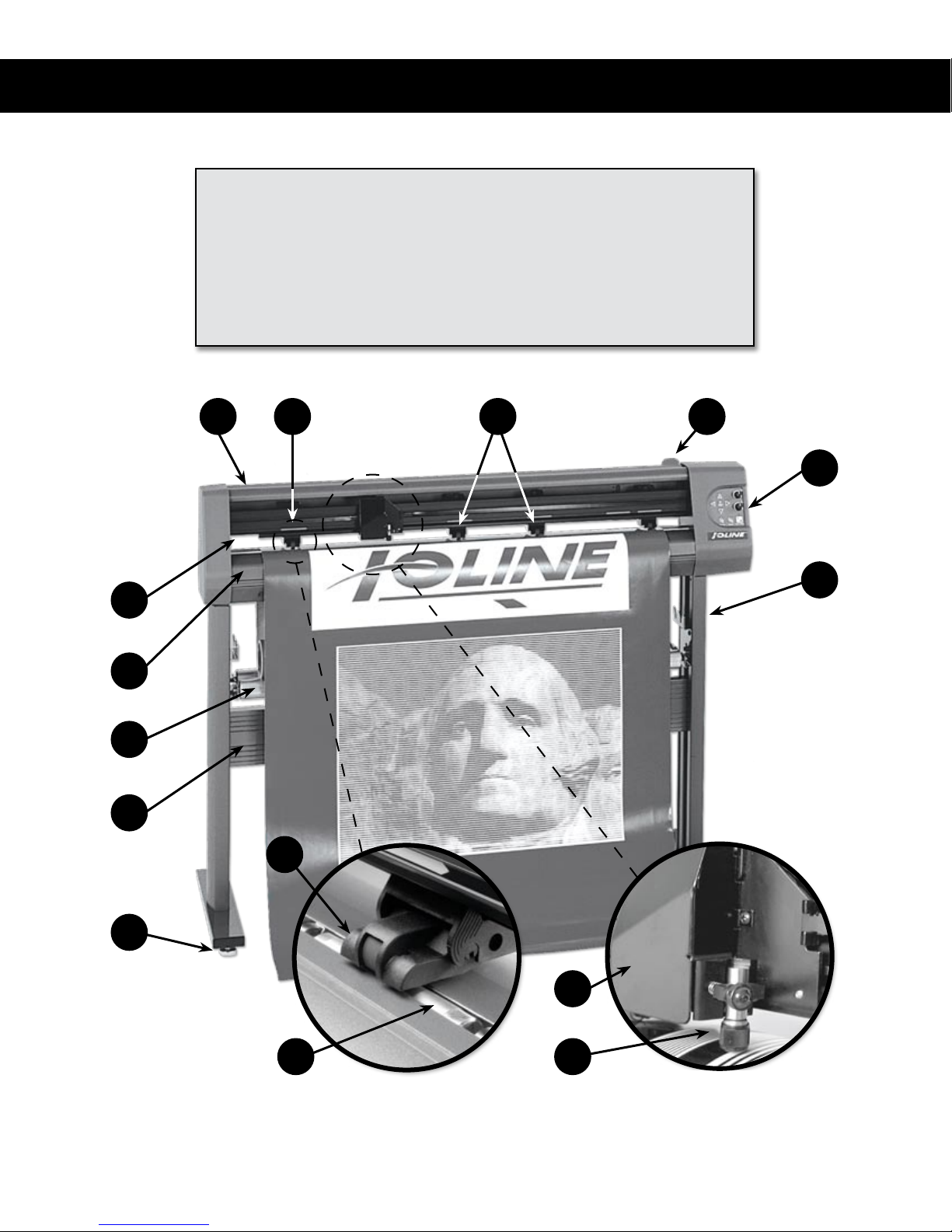
KEY
O
N
A. Dust Cover
B. Drive Shaft Marker
C. Carriage
D. Blade Holder
A B H
E. Idler Wheel
F. Drive Shaft
G. Pinchwheel
H. Pinchwheel Lever
E
I
J
M
L
K
G
F
Figure 1. The Ioline SmarTrac I/S Cutter Front View.
C
D
Page 5

Visual Reference Guide
KEY
5
O
I. Keypad
J. Stand Leg
K. Stand Leveling Foot
L. Cross-member
M. Media Roller
N. Platen
O. Traverse
P. LED Sensor
A B E H
I
J
N
M
L
K
C
G
D
Figure 2. The Ioline SmarTrac Contour (SC) Cutter Front View.
P
F
Page 6

Quick
Setup
Caution
Caution: The SmarTrac
is heavy and could cause
injury if it falls. A minimum
of two people are required to
safely unpack the plotter and attach it to the stand or cradle. One
person should hold the machine
while the second person screws it
to the legs.
Figure 4. Proper lifting pro-
cedure. Requires two people.
This Quick Start Guide shows how to assemble and setup the Ioline
I/S, SC-40 and SC-48 model cutters. Consult the SmarTrac User
Guide on the CD-ROM for more detailed information about installation and operation. The User Guide may be printed from the provided Adobe® Acrobat® viewer if necessary.
Step 1: Unpack
Remove the cutter, stand parts, and Accessory Kit from the box.
Check the Packing List. Always use two people when lifting the cutter, one person at each end. Save all of the packing materials.
Required tools
n Phillips screw driver
n 7/16-in wrench
Step 2: Assemble the Stand
(Optional for I/S 60 model)
Attach the Feet
Attach one foot to
each leg using three
1.5-in (long) Phillips
screws and three 7/16in hex nuts. Repeat
this procedure for
the other leg. Screw
all of the leg levelers halfway into the
ends of the stand
feet. Thread all four
levelers in equally to
ensure your cutter is
level and stable.
Leveler
Foot
Figure 5. Attach the feet.
Leg
Page 7

Connect the
Cross-Member
and Legs
The cross-member
is reversible and can
be attached upside
down or from either
side. Fit the crossmember snugly
into the rectangular
groove in one leg.
Align the holes in the
leg with the threaded
holes in the cross-member. Insert two 1-in (medium) Phillips screws
into the threaded holes. Leave them loose. Repeat this procedure for
the other leg. Tighten all four screws.
Figure 6. Connect the cross-member.
Cross-member
Quick Setup
7
Insert the Media
Roller
Rollers
Insert the front media
roller pins into the
notches in the front
of each leg. There are
extra notches to accommodate different
size rolls of media.
Find the matching
notches on the opposite leg to keep the
roller straight. Repeat
for rear media roller.
Figure 7. Insert the media rollers.
Notch
Step 3: Attach the Stand or Cradle
Place Cutter on the Stand
(I/S 85, 110 and 130 & SC40, and -48 models)
One person should
hold the cutter while
the other person positions it. Slide the tabs
on the bottom of the
cutter inside the top
of both legs. Make
sure that the holes in
the legs line up with
the threaded holes in
the tabs.
Tab
Figure 8. Place cutter on stand.
Page 8

8
Ioline SmarTrac Quick Start Guide
Place Cutter on
the Cradle
(optional on I/S 60)
Tab
Back
Front
Figure 9. Place cutter on cradle.
of the machine. Make sure that the holes line up. The media support
shaft ts in notches at the back of the cradle leg.
Have one person
hold the cutter while
the other person positions the cutter. Slide
bottom tabs of the
cutter outside the top
of both cradle feet.
The longer portion
of the foot should
extend from the back
Figure 10. Insert Screws in legs or cradle feet.
Insert the Screws
Have one person hold
the cutter while the
other person inserts
the screws to secure
the cutter to the legs or
cradle feet. Insert the
3
/8-in (short) Phillips
head screws though
the leg or cradle foot
and into tabs on the
cutter; Tighten.
Finish Assembly
Cut the plastic strap
that holds the carriage in place during
shipment and discard
it. Remove and discard all packing foam
from around the carriage to complete the
assembly.
Figure 11. Remove packing foam and plastic strip.
Page 9

Quick Setup
9
Step 4: Finish Installation
Connect the
Machine Cables
Make sure power is
off to the cutter (the
switch is placed in the
0 position). Connect
the serial or USB cable
and the power cord
to the panel on the
back of the right side
of the cutter. Plug the
machine power cable
into a wall socket or
surge protector.
Connect the
Computer Cable
With power to the
computer off, connect
the serial or USB cable
to one of the ports
on the back of the
computer. See the In-
stallation chapter of the
SmarTrac User Guide
for more information.
Power
Cable
Figure 12. Power cable and communication ports.
Figure 13. Computer communication ports.
Serial
Port
USB Ports
Serial Port
USB
Port
i
A USB cable is provided in the
Accessory Kit.
i
An adapter (not included) is required for 25-pin serial connections.
Note
Note
Install the
Software
Insert the installation
CD-ROM into the
computer CD-ROM
drive. The install
program should start
automatically. If it
does not, select Run
from the Start Menu.
Browse to the CDROM and double-click
on Install Ioline Con-
trol Center from the
list of options. Press
OK to start the install.
Install the Control
Center software.
Figure 14. The Ioline Control Center.
Install USB Drivers
Please see the guide labeled Installing USB Drivers for Ioline Products
on the CD-ROM for the driver installation process.
i
The Setup program also allows
installation of the electronic User
Guides and the necessary viewer.
Note
Page 10

10
Ioline SmarTrac Quick Start Guide
Step 5: Prepare to Cut
Load the Material
Roll
Place a roll of material onto the media
rollers. With the
pinchwheels up,
thread the material
through the machine.
Figure 15. Material loaded on media roller.
Position the Pinchwheels Over the Drive Shaft
Move the material and pinchwheels from side to side to nd a position
where the outermost drive wheels are on the material about 1 inch from
each edge, and over a drive shaft segment. Use the drive shaft markers
(Figure 16) to determine where to place the wheels. The long drive shaft
segment on the right
Drive Shaft
Marker
Drive Shaft
Segment
Figure 16. Place pinchwheels under drive shaft markers.
side of the machine
allows many pinchwheel positions for
a variety of material
widths. Evenly space
the inner idler wheel(s)
(I/S 85, 110 and 130 &
SC-40 and -48 models) over drive shaft
segments. Make sure
there is a minimum of
one inch between the
edge of the roll and the
stand leg.
Square the Material
Lift the pinchwheels off the drive shaft using the pinchwheel lever.
Pull enough material through the machine so that it reaches the roll.
Align the edge of
the material with
the edge of the roll,
making sure the
material is at and
square in the machine. Ensure that the
outer pinchwheels
are at least one inch
from the edge of the
material. Lower the
pinchwheels.
Figure 17. Align the material.
Page 11

Position the Material
Do not let the material become suddenly tight between the cutter
and the material roll. Manually unroll a few feet of material from
the roll to create a
slack loop behind
the machine. Use
the Arrow keys on
the keypad to move
material through the
cutter to check alignment. Adjust the material if necessary so
that it feeds straight.
Position the material
edge two inches in
front of the blade;
Place the carriage an
inch from the right
edge.
Figure 18. Leave slack in the material.
Quick Setup
11
Insert a Blade,
Load the Holder
Blade
Blade
Holder
in the Jaw
Unscrew the foot
from the blade
holder. Insert a blade
into the hole in the
blade holder, making sure it is fully
seated. Replace the
foot and adjust it so
that the blade tip is
barely inside the foot
with no blade exposed. Loosen the thumb screw on the carriage jaw
and insert the blade holder. The ange slides into the slot in the jaw.
Rotate the clamp down onto the ange and tighten the thumb screw
until the blade holder is held securely in place.
Foot
Flange
Figure 19. Inserting the blade (left) and the blade
holder (right).
Adjust the Blade
Exposure and
Force
i
Be very careful when handling
the blades as they are sharp and
brittle and the tips can chip or
break. Using a hard surface to
insert the blade may damage it.
Note
Turn the Force knob
on the keypad clockwise to maximum.
Press the Test Cut
key. There should be
little or no scoring of
the material. Turn the
foot 1/8-turn clockwise (from the bottom). Press the Test Cut key. Weed the test cut
pattern and examine cut quality. Continue adding blade exposure
Deeper
Cut
Figure 20. Adjusting the blade exposure.
Page 12

12
Ioline SmarTrac Quick Start Guide
and pressing Test Cut until the pattern weeds easily and the blade
leaves a clear scoring on the backing.
To extend blade life, only set as much Force and blade exposure as
is absolutely required to get a clean cut and good weed. Reduce the
Force in small increments and perform more test cuts until the test
cut pattern sticks slightly while weeding; Then, set the Force to the
previous position. Press and hold the Test Cut key for 3 seconds. The
cutter will cut a large test pattern as a nal check. Move the carriage
and material to a starting position for the rst le. Press the Set Ori-
gin key on the keypad. The light on the keypad will turn green.
The cutter is ready to cut. Refer to the User Guide and
your design software documentation for more information
about optimizing cutter performance.
Customer Service
Ioline Corporation is committed to providing quality service and
support to our customers. If you need assistance with an Ioline product, contact your local dealer or Ioline authorized service center. You
may also contact:
Ioline Customer Service Department
Monday through Friday
7:00 A.M. - 5:00 P.M. U.S. Pacic Time
Voice: 1.425.398.8282
Fax: 1.425.398.8383
support@ioline.com
www.ioline.com
 Loading...