

Page 1
Quick Start Guide
Ioline FlexJet E
Page 2

User Notice
Trademarks
Ioline FlexJet E is a trademark of Ioline Corporation. HP is a trademark of the Hewlett-Packard Company.
Other product names, logos, designs, titles, words or phrases mentioned within this publication may be
trademarks, service marks, or trade names of Ioline Corporation or other entities and may be registered in
certain jurisdictions including internationally.
Ioline Disclaimer
IOLINE CORPORATION PROVIDES THIS MANUAL “AS IS” WITHOUT WARRANTY OF ANY KIND,
EITHER EXPRESS OR IMPLIED, INCLUDING BUT NOT LIMITED TO THE IMPLIED WARRANTIES
OR CONDITIONS OR MERCHANTABILITY OR FITNESS FOR A PARTICULAR PURPOSE. IN NO
EVENT SHALL IOLINE, ITS DIRECTORS, OFFICERS, EMPLOYEES OR AGENTS BE LIABLE FOR ANY
INDIRECT, SPECIAL, INCIDENTAL, OR CONSEQUENTIAL DAMAGES (INCLUDING DAMAGES
FOR LOSS OF PROFITS, LOSS OF BUSINESS, LOSS OF USE OR DATA, INTERRUPTION OF BUSINESS
AND THE LIKE), EVEN IF IOLINE HAS BEEN ADVISED OF THE POSSIBILITY OF SUCH DAMAGES
ARISING FROM ANY DEFECT OR ERROR IN THIS MANUAL OR PRODUCT.
Limit of Liability Statement
It is the responsibility of the operator of the printer to monitor the performance of the printer and
maintain it in proper working condition by following the instructions in this Quick Start Guide and
the User Guide. It is the responsibility of the operator of the printer to follow all safety precautions and
warnings that are described in this User Guide. Ioline Corporation is not responsible for injuries that
may occur as a result of unsafe use. Ioline Corporation is not responsible for substandard operational
performance as a result of failure to maintain the printer as described in the Quick Start Guide and the
User Guide.
© 2003-2008 Ioline Corporation. All rights reserved. This manual may not be copied, photocopied, reproduced, translated, transmitted or converted to any electronic or machine-readable form in whole or in
part without prior written approval of Ioline Corporation.
Service and Support
If you require assistance with an Ioline product, your local Ioline dealer or authorized service center is
ready to help. Support information is also available 24/7 on the Ioline Web site—or you may contact Ioline
directly:
Ioline Corporation
14140 NE 200th Street
Woodinville, Washington 98072 U.S.A.
Ioline Customer Service Department
Monday through Friday
7:00 A.M. - 5:00 P.M. U.S. Pacific Time
Voice: 1.425.398.8282
Fax: 1.425.398.8383
support@ioline.com
www.ioline.com
Part Numbers: (Print) 109531 Rev. 1 • (File) 109620 Rev. 1
Page 3
The Ioline FlexJet E printer has many fast moving components.
Please read and follow these safety guidelines before beginning
operation of the printer:
n Do not try to repair the machine without factory authoriza-
tion. Only qualified service personnel should attempt any
disassembly or access to internal components. If external
mechanical adjustments are necessary, turn off the printer and
disconnect it from all power sources (both the computer and
the wall outlet).
Safety &
Cautions
n Be careful with hair, jewelry, or loose clothing near the printer.
They can become caught in the mechanical parts.
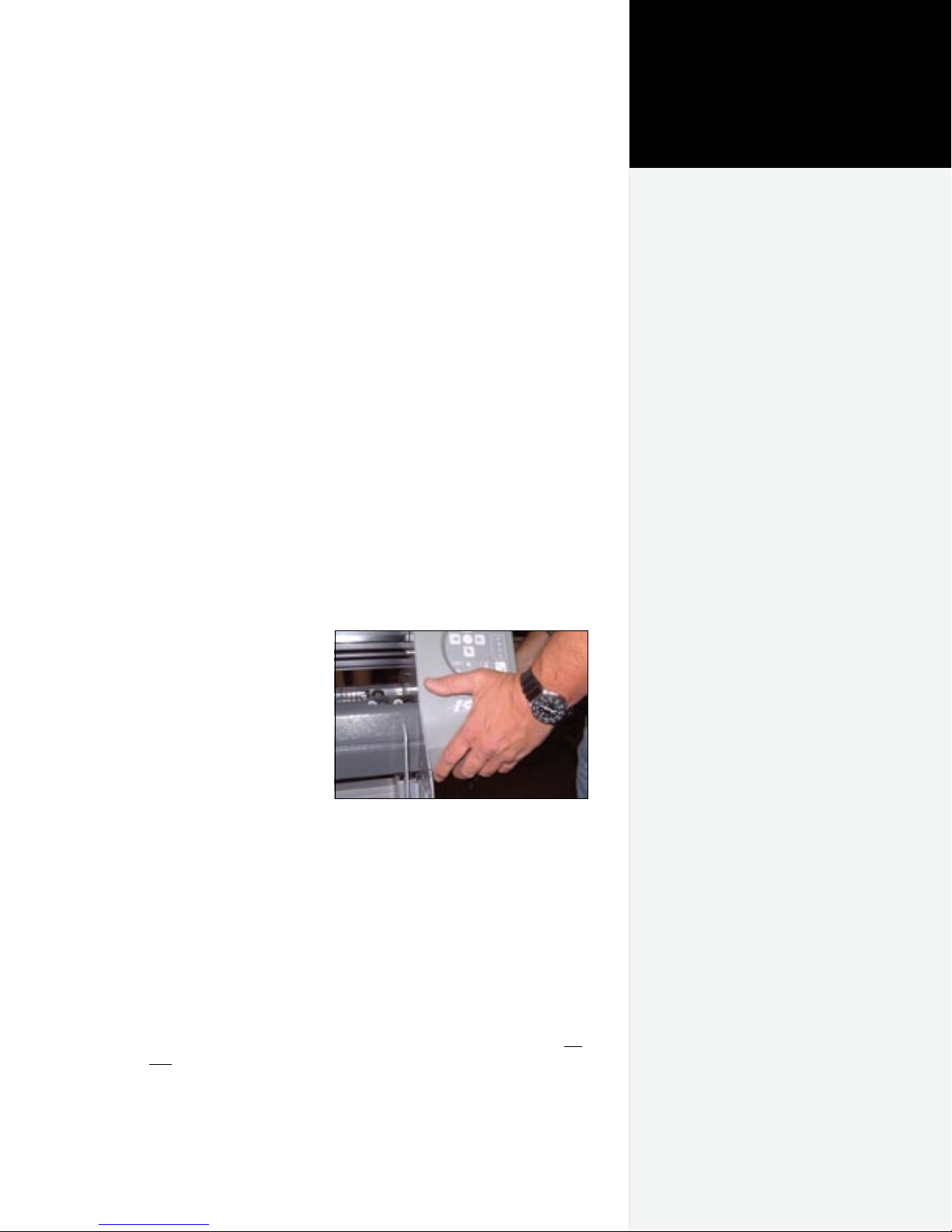
n Never attempt to move the carriage by hand when the power is
on. Always use the Arrow keys to move the carriage. To park
the carriage safely in
the Service Station
and protect the print
cartridges, press the
Clean button.
n Keep hands away
from the carriage
when the printer is in
operation. The car-
riage will automatically move to touch
the left end plate then
back to the right end
(the Service Station
position) when the
power is turned on.
n Never insert hands or other objects into the Service Station
area on the right side of the printer. The carriage occasionally
enters this area without warning and could collide with an
obstruction, potentially causing and injury.
Hold the bottom surfaces of the end covers
to avoid injury to your ngers.
n Be careful when moving or lifting the printer. Moving the print-
er requires at least 2 people. To avoid injury to your fingers, do
not lift the printer by the end plates. Hold the bottom surfaces
of the end covers to lift or move it. See Figure 1.
n Keep fingers away from the drive shaft when the printer is in
operation. Serious injury could result.
Page 4
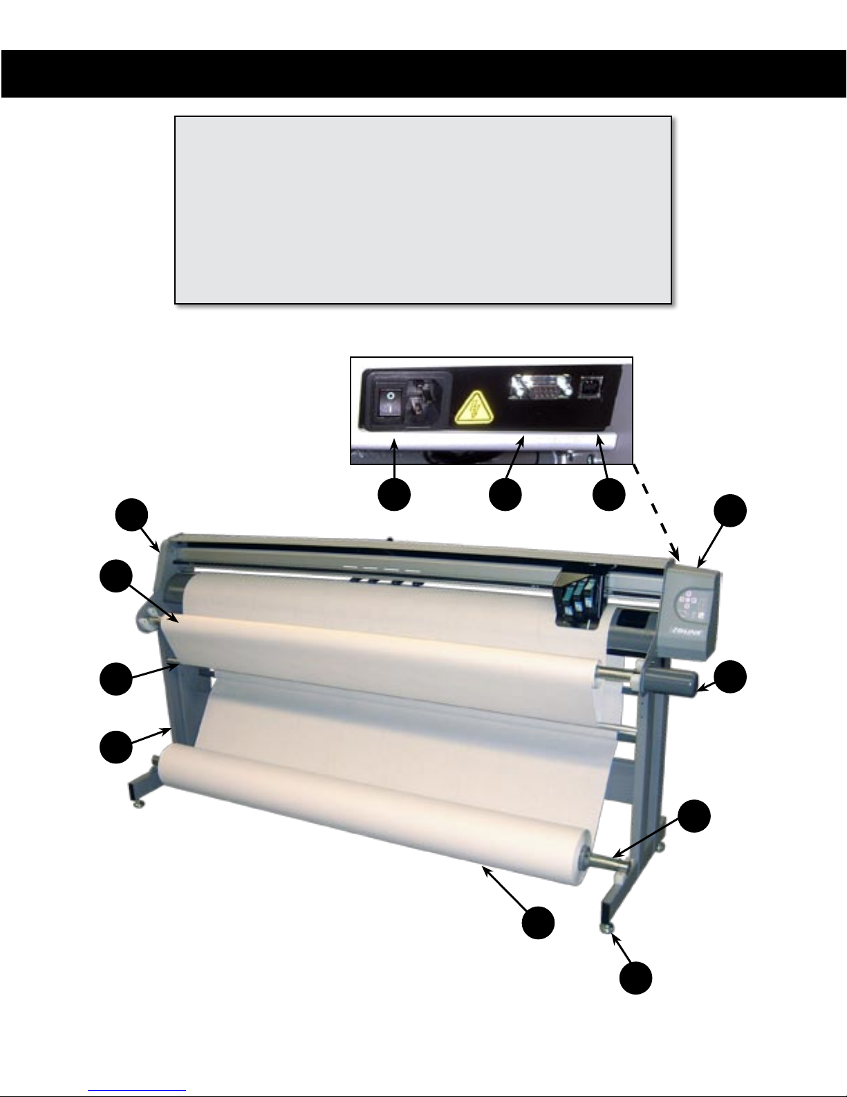
KEY
A
A. Left End Cover
B. Right End Cover
C. Take-up Motor
D. Stand Leveling Foot
E. Feed Roll
F. Take-up Shaft
Rear Panel Behind Right End Cover
G. Feed Shaft
H. Dancer Bar
I. Stand
AA. Power Switch
BB. Serial Port
CC. USB Port
AA BB
CC
B
F
H
I
C
G
E
4
The Ioline FlexJet E Printer Front View.
D
Page 5
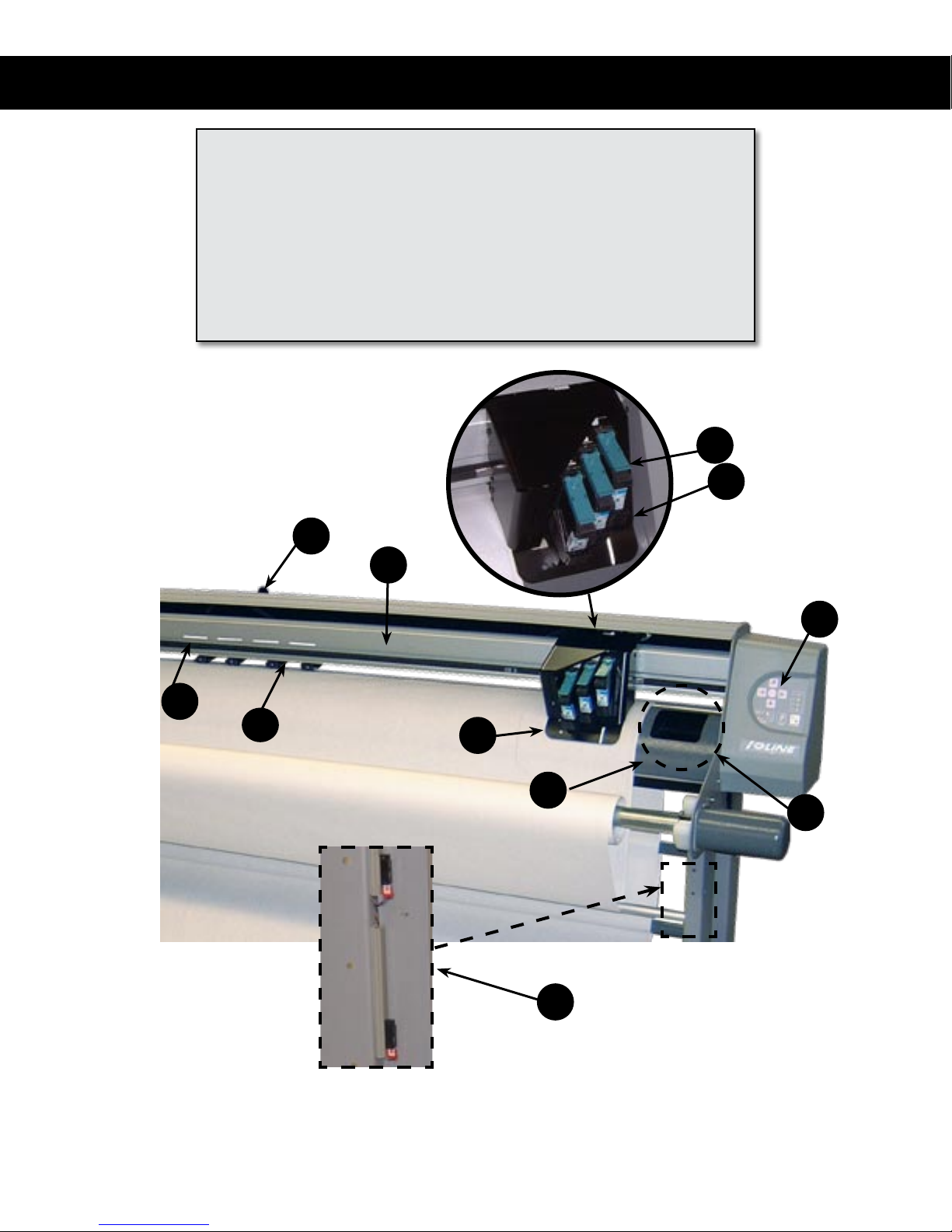
Visual Reference Guide
KEY
J. Drive Shaft Marker
K. Pinchwheel
L. Traverse or Carriage Rail
M. Carriage Assembly
N. Platen
P. Ink Cartridge Latch
R
L
Q. Ink Cartridge Stall
R. Pinchwheel Lever
S. Keypad
T. Service Station
U. Take Up Sensors
P
Q
S
J
K
The Ioline FlexJet E Printer Front View Close-up
M
N
T
U
5
Page 6

NOTES
6
Page 7
Assembly
This Quick Start Guide shows how to assemble and set up the Ioline
FlexJet E printer. Consult the FlexJet E User Guide on the CD-ROM
for more detailed information about installation and operation. Use
the provided Adobe® Acrobat® viewer to read and print the user
guide if necessary.
Unpacking the FlexJet E
Chapter 1
Assembly & Set-up
Remove the printer, stand parts, and Accessory Kit from the box
and check the packing list. Always lift the printer with two people,
one person holding the bottom of the end covers. (See Step 3 for more
details.) Save all packing materials.
Required tools
n Hex (Allen) and 7/16-inch wrenches
and grease (included)
n 7/16, 1/2, and 9/16-inch open
ended or two adjustable wrenches
n A level
n Rubber headed mallet
n Phillips screw driver
i
Save all packing materials.
Note
Caution
The FlexJet E printer is
heavy and could cause
injury if it falls. A minimum
of two people are required
to safely unpack the printer and
attach it to the stand.
Page 8
8
Ioline FlexJet E Quick Start Guide
Step 1: Assemble the Right Leg
1. Find the right leg assembly. It has small sensors attached to it
inside one of the channels. The leg is also labeled, “RIGHT LEG
ASSEMBLY, FJe PRINTER”
2. Find the right foot. It has a plastic block on it.
Sensors on
Right Leg
Plastic Block
on Right Foot
3. Insert the right foot into the right leg between the flanges on
the bottom of the leg so that the plastic block and the small sensors are both on the same side of the assembly.
Page 9

4. Align the holes in the foot with those in the leg. 6 of the holes
should align when correctly positioned.
5. Insert two 1.5-inch long 1/4-20 screws through the foot and
into the threaded nuts in the stand leg. Turn them loosely by
hand only.
1.5-inch screw—at actual size.
1.5-in Screw (2)
9
6. Insert four 1.5-inch long 1/4-20 screws through the holes in
the stand leg and all the way through the foot. Turn four nuts
loosely by hand onto the end of the screws.
1/4-20 Nut (4)
1.5-in Screw (4)
7. Tighten all six screws with the included T-handle Allen wrench
and a 7/16-inch open ended wrench on the four nuts.
Page 10

10
Ioline FlexJet E Quick Start Guide
Step 2: Assemble the Left Leg
1. Find the left leg assembly. A piece of plastic tape is attached to
the inside of one channel. It is also labeled, “LEFT LEG ASSEM-
BLY, FJe PRINTER”
2. Find the left foot. It has a metal bracket with two bearings
bolted to it.
Left Leg with
Plastic Tape in Channel
Metal Bracket with Bearings
on Left Foot
3. Insert the left foot into the left leg between the flanges on the
bottom of the leg so that the metal bracket is on the side opposite the channel with the plastic tape in it.
Page 11

4. Align the holes in the foot with those in the leg. 6 of the holes
should align when correctly positioned.
5. Insert two 1.5-inch long 1/4-20 screws through the foot and
into the threaded nuts in the stand leg. Turn them loosely by
hand only.
1.5-in Screw (2)
11
6. Insert four 1.5” long 1/4-20 screws through the holes in the
stand leg and all the way through the foot. Turn four nuts
loosely by hand onto the end of the screws.
1.5-in Screw (4)
1/4-20 Nut (4)
7. Tighten all six screws with the included T-handle Allen wrench
and a 7/16-inch open ended wrench on the four nuts.
Page 12

12
Ioline FlexJet E Quick Start Guide
i
The cross-member is reversible
and can be attached from either
side.
Note
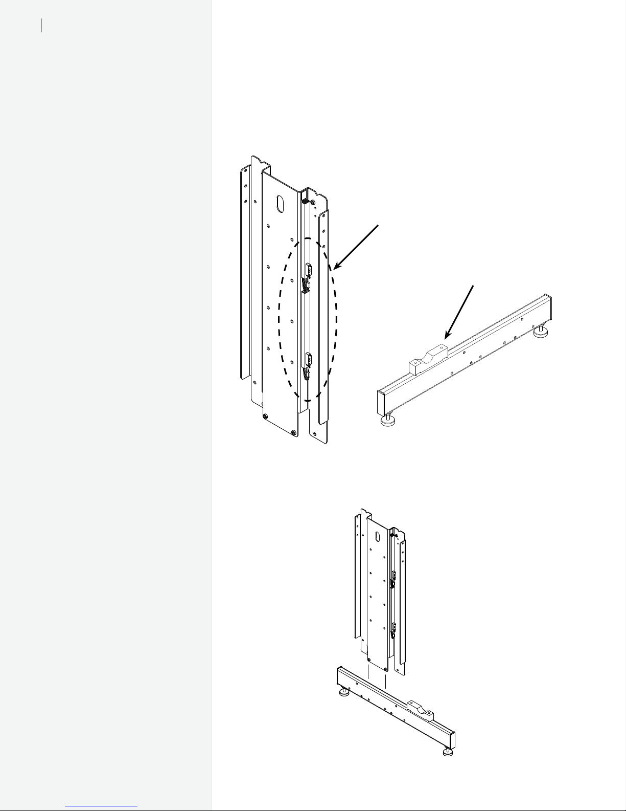
Step 3: Attach the Cross-member
1. Examine the diagrams showing proper placement of the crossmember in the figure below before proceeding with assembly.
2. Align the correct holes in the right leg with the threaded holes
in the cross-member.
3. Insert two 1-inch socket head screws into the threaded holes.
Leave them loose.
4. Repeat this procedure for the left leg. Make sure that the support
blocks on both leg point the same direction.
5. Place the stand assembly upright.
6. Tighten all four cross-member screws.
1-in Screw (4)
Right Leg
Caution
Do not hold the printer
head by the bottom edge
of the end plates when
attaching it to the stand. Fingers
and hands might get pinched
between the end plates and stand
legs. Hold the bottom of the end
covers when handling the printer.
Cross-member
Plastic
Support
Block
Proper placement of the cross-member on FlexJet E model.
1-in screw—at actual size.
Page 13

Step 4: Attach the Top Bar (2H+ FJE Models Only)
1. Some FJE Models with two or more print heads include a high
speed printing kit with a rolling rear top bar. On these machines there are two heavy aluminum rods and one light short
aluminum rod included with the printer. The shorter heavy
aluminum grey rod is the rolling top bar attached to the stand.
The longer heavy aluminum rod (painted black on later models) is the rear dancer bar explained later in Paper Loading,
Step 7.
2. Find the top bar support hardware on the left leg. It is holding
a silver spacer against the left leg.
Top Bar Support
Hardware on Left Leg
13
3. Gather two 7/16-inch or adjustable open ended wrenches.
Hold one of the nuts on the left support hardware with one
wrench and turn the other nut with the other wrench. Take the
‘C’ shaped spacer off the support when the nuts are loose and
set it aside.
Page 14

14
Ioline FlexJet E Quick Start Guide
4. Find the top bar support hardware on the right leg.
Top Bar Support
Hardware on Right Leg
5. Align the top bar shaft with the right support hardware and
slide the shaft on to it until it stops.
6. While holding the bar, move to the left stand leg and find the
left support hardware. Push the hardware assembly away from
the center of the stand until it stops.
Page 15

7. Align the top bar with the hardware then push the hardware
from outside the stand so that it is inserted into the top bar.
8. Re-install the ‘C’ shaped spacer removed in Step 3 then tighten
the nuts with two 7/16-inch or adjustable open ended wrenches.
15
9. Install the protective cap on the exposed thread on the left leg.
Page 16

16
Ioline FlexJet E Quick Start Guide
Step 5: Level the Stand
1. Use the wrench to loosen the 9/16-in lock nut on both of the right
leg leveling feet, turning them counter-clockwise. Place a level
across the top of the right stand leg. (See Figure)
2. Turn the 1/2-in nut on each leveling foot counterclockwise to
lower the foot or clockwise to raise the foot until the leg is level.
Repeat this procedure for the left leg.
Check Stand Level
on legs rst
After legs are level,
check stand level at
Stand Leveling
Foot
Cross-member
Placement of the level on the stand.
3. Place a level on the cross-member. Repeat the adjustment
procedure as above except adjust both front and rear levelers
on each leg the same amount so that the legs stay level but the
cross-member moves. Adjust the threaded feet until the stand
is level on the cross-member.
4. Check the level of the legs again and make small adjustments
as necessary until the stand is level in both directions.
5. Tighten all of the 9/16-in lock nuts on the levelers by turning
them clockwise.
Page 17

Step 6: Attach the Printer to the Stand
1. Using two people, lift the printer head onto the stand. The
front (carriage side) of the printer should face the same direction as the support blocks on the stand feet. Make sure the pin
at the rear of each endplate rests in the ‘V’-shaped notch in the
rear of both legs.
Hold the bottom surface of the
end cover (see image in caution
box at right). DO NOT HOLD
THE BOTTOM EDGES OF THE
END PLATE.
End
Cover
17
Printer head
End Plate
Caution
Do not hold the printer
chassis by the bottom edge
of the end plates when attaching
it to the stand. Fingers and hands
might get pinched between the
end plates and stand legs. Hold the
bottom surface of the end covers
when handling the head.
The end plates slide over the stand legs as shown above. Do not hold the end plates
when you install the printer head (as shown at right).
Page 18

18
Ioline FlexJet E Quick Start Guide
2. Check that the holes in the endplate line up with the threaded
holes in the leg. If they do not align, check to make sure that the
rear alignment pin is resting in the rear notch on both legs.
3. Insert four 5/8-in button-head screws through the two holes in
both end plates to connect the head to the stand. Tighten all
four screws with the included T-handle wrench.
Caution
Make sure power to the
machine is off before connecting the cables.
5
/8-in Screw
(2 per side)
Print head attachment
5
/8-in screws—shown here at actual size.
Step 7: Connect the Paper Sensor Cable
1. Make sure power is off to the machine. Find the small plug
clipped to the bottom inside edge of the right endplate.
Page 19

2. Pull the looped end of the cable out of the front clip so that the
plug hangs free. Make sure part of the cable remains within the
clip as shown.
3. Align the cable with the plug on the right stand leg then connect the plug with the socket. They will only connect one way.
Make sure the locking latch snaps into the catch.
19
Page 20

20
Ioline FlexJet E Quick Start Guide
Step 8: Check Machine Level
1. Place a level on the platen so that it is parallel to and in front of
the drive shaft.
2. Make small adjustments to the threaded feet in the stand if the
machine is not level. Note: If the machine is difficult to level,
check the printer for shipping damage and contact Ioline Customer Service.
Level
Threaded Leveling
Stand Feet (4)
Page 21

21
Step 9 : Connect the Communication and Power Cables
1. Turn power off to the printer. Off is marked with a, “0,”.
2. Connect the supplied serial cable and power cord to the panel on
the back of the right side of the printer. Lock the serial cable to
the port on the printer with the thumb screws.
3. Plug the printer power
cable into a wall socket or
surge protector.
4. Make sure that power is
off to the computer.
5. Connect the serial cable to
a 9 pin-male-serial port on
the back of the computer.
Tighten the thumbscrews.
The serial port and power socket.
i
Note: The FlexJet E User Guide
contains detailed instructions for
communication setup.
i
On the FlexJet E printer, off is
marked with a, “0,” and on with
a,“1.”.
Note
Note
Step 10: Install the Software
1. Insert the installation CD-ROM into the computer CD-ROM
drive. The install program should start automatically. If it does
not, select Run from the Start Menu. Browse to the CD-ROM
and double click on iosetup.exe. Press OK to start the install.
2. Install the Ioline FlexPlot and Control Center software. USB
drivers are installed automatically.
Hint
The Installation Disk also
includes electronic copies of
the FlexJet E User Guide and
FlexJet E Quick Start Guide. It
is recommended that you install
these along with Adobe Acrobat
(also included on the disk) to
make help easily accessible.
Page 22

22
Ioline FlexJet E Quick Start Guide
NOTES
Page 23

Paper Loading
Step 1: Loading the Feed Roll
1. Before loading a new paper roll always make sure the drive
shaft is clean. See the Routine Maintenance section in the FlexJet
E User Guide for more details.
2. Place a paper hub in each end of the paper roll. Use a rubber
mallet to insert the hubs.
Chapter 2
Preparing to Print
3. Slide the feed shaft through the paper hubs and the paper roll.
If a paper hub falls out, press it firmly back into the end of the
paper roll and set it with a rubber mallet.
Support
Block w/
Bearings
Feed
Shaft
Paper Roll
(Unrolls from behind)
Paper Hub (2)
Support Block
(apply grease)
Flanged Coupling
Caution
Never touch the take-up
key or anged coupling
while they are rotating.
Serious
personal
injury
could result. Turn
power
off rst.
Page 24

24
Ioline FlexJet E Quick Start Guide
4. For paper narrower than 70-in, center the paper roll on the feed
shaft. Make sure the hubs remain securely in place. For paper
greater than 70-in in width, offset the paper to the left slightly
to avoid covering the Service Station area. Also leave a minimum 1/4 inch gap between the paper edge and the edge of the
fan on the left side of the rear cover of the machine.
5. Use the supplied hex wrench to tighten both screws on each
paper hub.
6. IMPORTANT: Apply a light coating of grease (supplied in the
Accessory Kit) to the right support block.
7. Lift the feed shaft and paper roll into the support blocks. Make
sure the paper unrolls from behind and towards the printer.
Step 2 : Loading the Take-up Roll
1. Turn on the power to the printer with the switch on the back of
the right cover.
2. If the take-up shaft has printed markers on it, remove them. See
Unloading Completed Markers in the Ioline FlexJet E Printer in
the FlexJet E User Guide for details.
3. Use the keypad Unroll key to rotate the take-up key until it is
oriented perpendicular to the support block opening as shown
below.
4. Put the take-up shaft into the front support blocks with the
flanged coupling at the right (keypad) end. Rotate the shaft
until the slot in the flanged coupling is aligned with the takeup key. When the shaft slot and the key are aligned, push the
take-up shaft into place until it is seated in the support block.
Rectangular
slot
Take-up
Shaft
Flanged
Coupling
Position take-up
key as shown
Support Block
The slot in the anged coupling on the take-up shaft ts into the key in the right front
support block
Page 25

Step 3 : Feeding Paper
25
The figure below shows the proper paper paths. The left side of
the diagram shows the paper path for a 1H FlexJet E. The right side
shows the proper path for a FlexJet E with 2 or more heads and a
high speed printing kit.
1. If the pinchwheels are lowered, raise them by pushing the
pinchwheel lever away from the machine.
2. Pull a long leader of paper off of the paper roll and insert it
through the stand, behind the printer head, over the platen,
and between the platen and pinchwheels.
3. Temporarily lock the paper in place by pulling the pinchwheel
lever toward the machine to lower the pinchwheels.
Front
Dancer Bar
Take-up
Shaft
Hint
An alternate take-up method that
will ease removal of markers is
to slide a cardboard tube over
the take-up shaft then tape paper
to the tube. The cardboard tube
will rotate slowly at rst and may
not raise the front dancer bar
but will still roll up completed
markers. Simply slide the tube off
the take up shaft when plotting is
complete.
i
Ensure that the paper is properly
positioned for its width. See Step
1 under Paper Loading earlier in
this chapter.
Note
Feed Roll
Proper Paper Path
1H FlexJet E
Proper Paper Path
2H+ FlexJet E
Page 26

26
Ioline FlexJet E Quick Start Guide
Step 4 : Taping Paper to the Take-Up Shaft
1. Stand in front of the machine.
2. Temporarily attach a short piece of masking tape to the center
of the cover on top of the machine.
3. Grasp the front edge of the paper. Push the pinchwheel lever to
raise the pinchwheels.
4. Hold the front edge of the paper with both hands and pull 20”
(51 cm) of paper over the platen and under the take-up shaft
(see Step 3 for the proper paper path). On machines with the
high speed printing kit, make sure the paper covers the rear
rolling top bar.
5. Apply pressure to the feed roll with a foot so that it does not
turn.
6. Align the paper by gently pulling it while moving it left and
right until the tension feels even. Attach the paper to the takeup shaft using the piece of tape stuck to the cover.
7. Tape the right and left ends of the paper (about 2” or 5 cm in
from the edge) to the take-up shaft.
Tape the paper
in 3 places
Do not cover the hole in the platen
with paper.
Page 27

Step 5: Positioning the Pinchwheels
1. Ensure that the paper is loaded as described, that the right paper
edge does not encroach on the Service Station area and the left
edge does not touch the fan on the back of the machine.
2. Raise the pinchwheels (if they are not up) by pushing the lever
away from the machine.
3. Move the pinchwheels to the proper position. See Figure below.
Do not place a pinchwheel over any smooth portion of the drive
shaft. Use the white markers on the carriage rail to find drive
shaft segments when they are covered by paper.
27
Pinchwheel
White Driveshaft Markers
Drive Shaft
Segment
Drive Shaft
Bearing
Step 6 : Insert Front Dancer Bar
1. Lower the pinchwheels (if they are not down) by pulling the
lever toward the machine.
2. Insert the front dancer bar into the front dancer bar channel.
Front Dancer
Bar (Silver
light rod)
Page 28

28
Ioline FlexJet E Quick Start Guide
Step 7 : Insert Rear Dancer Bar (2H+ FJE Models Only)
1. FJE models with two or more printheads and the high speed
printing kit require that a heavy dancer bar is inserted in the
rear dancer bar channel (see paper path in Step 3).
2. Take the heavy dancer bar (painted black on some models) and
insert the ends into the notches in the stand legs on the back of
the machine as shown in the image below.
3. Use a hand on the rear rolling bar to slow rotation as the dancer
bar slides into the channel and forms a rear paper loop.
Notch in Stand Leg
Preparing to Print
1. Turn on the power (if it is not already on). There is a brief
pause then the carriage will move to the left end plate then return for a cleaning in the Service Station. After the initial startup process is complete, the OK light turns red and the Square
light turns green.
2. Use the Left Arrow key to move the carriage out of the Service
Station.
3. Remove the protective strip from the bottom of the ink cartridge. Insert the included ink cartridge by lifting the latch, inserting the cartridge, then closing the latch until it locks down.
4. Press the Left (or Right) Arrow key to move the carriage over
the paper until the white marker on the base is over the desired
starting point of the marker.
5. Press the Set Origin key. The OK light will turn green. The
printer is ready to print.
Test the Setup
1. Start the Software.
a. Close all programs that might be using serial port that the
FlexJet E is connected to.
b. Start the FlexJet E Control Center software. A link to the
program is in the Start Menu under Programs>Ioline.
c. A message may appear that the Control Center was un-
able to communicate with the FlexJet E. If you see this
message, click on Yes. When the program starts, open the
menu Communications>Settings. Choose the COM port
that the FlexJet E is connected to. Leave the baud rate set
at 38,400 since this is the default set at the factory.
Page 29

Communications error message.
d. Press the Get Plotter Data button to ensure the connection is
established.
2. Send Test Plot File
a. Select Send Plot File from the File Menu.
b. Browse to the folder c:\ioline\calibrate\.
c. Double click on the test plot file 40x8.plt to send it to the
printer.
d. When the printer prints the test file correctly, the machine
is ready for printing makers.
29
e. Close the FlexJet E Control Center.
3. Send Markers
a. Start FlexPlot or your apparel design software.
b. Setup communications so that the COM port and baud rate
are the same in the FlexJet E and the software. Refer to the
FlexPlot User Guide and FlexJet E User Guide or the manual
of your apparel design software for more information.
c. Send markers to the FlexJet E directly from the software.
Getting Help
Refer to Troubleshooting under the FlexJet E User Guide for assistance with common issues. Upon request, Ioline Customer Service
also offers a more detailed publication—the FlexJet E Service Manu-
al—which contains expanded troubleshooting information.
Customer Service
Ioline Corporation is committed to providing quality service and
support to our customers. If you need assistance with an Ioline product, contact your local dealer or Ioline authorized service center. You
may also contact:
Ioline Customer Service Department
Monday through Friday
7:00 A.M. - 5:00 P.M. U.S. Pacific Time
Voice: 1.425.398.8282
Fax: 1.425.398.8383
support@ioline.com
www.ioline.com
Page 30

30
Ioline FlexJet E Quick Start Guide
NOTES
Page 31

31
Page 32

32
Ioline FlexJet E Quick Start Guide
NOTES
 Loading...