

Ioline FlexJet Service Manual
Ser vice Manual
Ioline FlexJet™

User Notice
Trademarks
Ioline and FlexJet are trademarks of Ioline Corporation. HP is a trademark of the Hewlett-Packard Company. Other product names, logos, designs, titles, words or phrases mentioned within this publication
may be trademarks, service marks, or trade names of Ioline Corporation or other entities and may be
registered in certain jurisdictions including internationally.
Ioline Disclaimer
IOLINE CORPORATION PROVIDES THIS MANUAL “AS IS” WITHOUT WARRANTY OF ANY KIND,
EITHER EXPRESS OR IMPLIED, INCLUDING BUT NOT LIMITED TO THE IMPLIED WARRANTIES
OR CONDITIONS OR MERCHANTABILITY OR FITNESS FOR A PARTICULAR PURPOSE. IN NO
EVENT SHALL IOLINE, ITS DIRECTORS, OFFICERS, EMPLOYEES OR AGENTS BE LIABLE FOR ANY
INDIRECT, SPECIAL, INCIDENTAL, OR CONSEQUENTIAL DAMAGES (INCLUDING DAMAGES
FOR LOSS OF PROFITS, LOSS OF BUSINESS, LOSS OF USE OR DATA, INTERRUPTION OF BUSINESS
AND THE LIKE), EVEN IF IOLINE HAS BEEN ADVISED OF THE POSSIBILITY OF SUCH DAMAGES
ARISING FROM ANY DEFECT OR ERROR IN THIS MANUAL OR PRODUCT.
Limit of Liability Statement
This manual is provided for informational purposes only. The contents are subject to change without
notice and Ioline Corporation assumes no responsibility for any errors that may be contained herein.
Ioline has made every effort to make the FlexJet easy to operate, maintain, and repair. It is the responsibility of the operator of the printer to monitor the performance of the printer and maintain it in proper
working condition by following the instructions in this manual and in the FlexJet User Guide and to
follow all safety precautions and warnings that are described in these publications. Ioline Corporation is
not responsible for injuries that may occur as a result of unsafe use. Ioline Corporation is not responsible
for substandard operational performance as a result of failure to maintain the printer as described in this
manual and in the FlexJet User Guide.
© 2003-2005 Ioline Corporation. All rights reserved. This manual may not be copied, photocopied, reproduced, translated, transmitted or converted to any electronic or machine-readable form in whole or in
part without prior written approval of Ioline Corporation.
Service and Support
If you require assistance with an Ioline product, your local Ioline dealer or authorized service center is ready
to help. Support information is also available 24/7 on the Ioline Web site—or you may contact Ioline directly:
Ioline Corporation
14140 NE 200th Street
Woodinville, Washington 98072 U.S.A.
Ioline Customer Service Department
Monday through Friday
7:00 A.M. - 5:00 P.M. U.S. Pacic Time
Voice: 1.425.398.8282
Fax: 1.425.398.8383
support@ioline.com
www.ioline.com
Part Number: (File) 108675 Rev. 0

Ioline FlexJet™
Ser vice Manual


Images & Illustrations
Figure 1. Proper lifting procedures for the FlexJet . .......................................................... xiii
Figure 2.
Figure 3.
Figure 4.
Figure 5.
Figure 6.
Figure 7.
Figure 8.
Figure 9.
Figure 10.
Figure 11.
Figure 12.
Figure 13.
Figure 14.
Figure 15.
Figure 16.
Figure 17.
Figure 18.
Figure 19. LED lights
Figure 20. Keypad LED error codes
Figure 21.
Figure 22. HP cartridges have an ink level indicator
Figure 23.
Figure 24.
Figure 25.
Figure 26.
Figure 27.
Figure 28.
Figure 29.
Figure 30.
Figure 31.
Figure 32.
Figure 33.
Figure 34.
Figure 35.
Figure 36.
Figure 37.
The Ioline FlexJet Printer front view . ................................................................. xvi
The Ioline FlexJet Printer rear view . ................................................................. xvii
The Ioline FlexJet Printer front view close-up ............................................... xviii
The Ioline Flexjet . ....................................................................................................19
Paper direction . ........................................................................................................ 21
Carriage movement . ................................................................................................21
Workow: output direct from CAD software (without FlexPlot) . .............. 23
Workow using FlexPlot for le conversion and output ............................ 23
FlexJet Control Center main menu . ................................................................ 25
The Ioline Flexjet power supply . .......................................................................... 29
Rear power panel assembly . .................................................................................. 29
Service Station assembly . ....................................................................................... 30
Pinchwheel assembly . .............................................................................................. 30
Ink cartridges: HP 51645A . .................................................................................... 30
FlexJet logic board (Rev 1, above; Rev 2 below) . ..............................................31
Carriage assembly with cover on . ........................................................................ 32
Carriage assembly with cover off . ........................................................................ 32
on the keypad . ................................................................................... 36
. ................................................................................ 36
The correct paper feeding path on the Ioline FlexJet Printer . ...................... 42
. ...............................................44
The ink cartridge is dirty, dry, or empty . ............................................................ 44
The ink cartridge requires cleaning . ....................................................................45
Damaged and dirty print cartridge . ..................................................................... 45
Use a deliberate frame gap to help calibrate . .................................................... 46
The Cartridge Calibration window in the Control Center . ................ 47
The Cartridge Alignment dialog box . .................................................................. 47
Increase the alignment value for cartridge #2 to improve line quality . .......47
Decrease the alignment value for cartridge #2 to improve line quality . ..... 47
The Motion Adjust window . .................................................................................. 48
The heads are drawing the lines too late on this plot . .................................... 48
The Frame Gap window . ........................................................................................48
Frame gaps on the plot . .......................................................................................... 49
Frame gaps may indicate that the FlexJet platen or stand is not level . ........ 49
The height-adjusting spacer . .................................................................................. 49
The ink stall can crack if the cartridge door is not closed and locked ........ 50

Figure 38. Carriage noise may indicate a dirty or faulty wheel ........................................50
Figure 39.
Figure 40.
Figure 41.
Figure 42.
Figure 43.
Figure 44.
Figure 45.
Figure 46.
Figure 47.
Figure 48.
Figure 49. Rotate the v-wheels free of the traverse rail . ................................................... 66
Figure 50.
Figure 51.
Figure 52.
Figure 53.
Figure 54.
Figure 55.
Figure 56.
Figure 57.
Figure 58.
Figure 59.
Figure 60.
Figure 61.
Figure 62.
Figure 63.
Figure 64.
Figure 65.
Figure 66.
Figure 67.
Figure 68.
Figure 69.
Figure 70.
Figure 71.
Figure 72.
Figure 73.
Figure 74.
Figure 75.
Figure 76.
Figure 77.
Figure 78.
Figure 79.
Figure 80.
Figure 81.
Replacing the fuse . ................................................................................................... 51
A good transitor on the left; the one on the right is blown ..........................52
Testing the Y-Axis motor . ....................................................................................... 54
Mechanical, electrical and electronic diagnostics ow chart . ......................... 61
Removing the right end cover ............................................................................... 64
Loosen the belt tensioner . .....................................................................................64
The carriage cover screw . ......................................................................................65
Unclip the belt from both ends of the carriage . ............................................... 65
Loosen the carriage wheel lock . ...........................................................................66
Gently press down on the carriage . .................................................................... 66
Carriage installation . ................................................................................................67
Use the spacer when attaching each swing arm . .............................................. 67
The carriage belt tensioner . ..................................................................................68
Install the carriage cover . ....................................................................................... 68
Remove the cover .................................................................................................... 69
Install the carriage cover . ....................................................................................... 70
Remove the logic board cover plate .................................................................... 70
Unplug the feed motor and encoder cables from the logic board . ..............71
Unplug the ribbon cables . ......................................................................................71
Make a loop in the ribbon cable to the left of the carriage . .......................... 72
Carriage installation . ................................................................................................73
The carriage belt tensioner . ..................................................................................73
Install the carriage cover . ....................................................................................... 74
There should be a small gap in the ribbon cable loop . .................................... 75
The loop in the cable should not touch the left endplate . ............................. 75
Secure the sleeving with tape . ............................................................................... 76
Remove the right end cover . ................................................................................. 77
Remove the screws and let the keypad hang .....................................................77
Remove the carriage cover . ................................................................................... 77
Install the ink cartridges and turn the power on . .............................................78
Loosen the carriage catch bracket . ......................................................................78
Cover the spit wells . ............................................................................................... 78
Two lines in the spit well holes . ............................................................................ 79
Use the plastic thumbscrew to adjust the lines if necessary . ........................79
Y Fine adjustment is performed within the Control Center . .................... 80
Watch the gap between the carriage and Service Station . ........................80
The Service Station stop screw . ...................................................................... 81
Small gap between the screw and the Service Station . .............................. 82
Tighten the nut to hold the stop bracket . .......................................................... 82
Unplug the take-up motor . .................................................................................... 83
Remove the right cover . ......................................................................................... 83
Unscrew the PCB cover . ........................................................................................ 83

Figure 82. Remove the logic board cover ............................................................................. 83
Figure 83.
Figure 84.
Figure 85.
Figure 86.
Figure 87.
Carefully unplug connections to the board ....................................................... 84
Carefully remove the logic board ........................................................................ 84
Inspect the connections to the logic board ....................................................... 85
Remove the keypad screws and bracket. Unplug the keypad cable .............87
Tighten the screws on the Y-Axis transmission . ...............................................88


Table of Contents
Safety & Cautions
Warranty Policy
Ioline warranty policy ...................................................................................... xiv
How to use this manual
Where to nd information ................................................................................................ xv
What’s in this Service Manual ........................................................................... xv
Visual Reference Guide
Chapter 1 Overview
Product overview ..................................................................................................................... 19
Supported languages ............................................................................................................ 19
Specications ......................................................................................................................... 20
How the FlexJet works ....................................................................................................... 21
Paper movement .................................................................................................................. 21
Carriage movement ............................................................................................................. 21
Serial number identication ............................................................................................... 21
Glossary .................................................................................................................................. 22
Software setup options ....................................................................................................... 22
Power on ...................................................................................................................................... 24
Installing FlexPlot and the Control Center ................................................................ 24
The FlexJet Control Center ............................................................................................... 25
Overview ................................................................................................................................ 25
Changing system settings .................................................................................................... 25
Control Center menu bar features ................................................................................. 26
File ........................................................................................................................................... 26
Communications .................................................................................................................. 26
Tools ........................................................................................................................................ 26
Help ......................................................................................................................................... 26
Control Center menu options ........................................................................................... 27
Software Version ................................................................................................................... 27
Cartridge Count ................................................................................................................... 27
Get Plotter Data .................................................................................................................. 27
Plotter Data (check box) .................................................................................................... 27
Line Width .............................................................................................................................. 27
Scale ......................................................................................................................................... 27
Frame Size .............................................................................................................................. 27

Quality Setting ...................................................................................................................... 28
Measurement Units .............................................................................................................. 28
Chapter 2 Nomenclature
Product components ............................................................................................................. 29
General troubleshooting ...................................................................................................... 33
Error messages ......................................................................................................................... 33
Chapter 3 Troubleshooting & Testing
Control Center software errors ....................................................................................... 34
Keypad error codes ................................................................................................................. 36
Legend ..................................................................................................................................... 36
Power problems ........................................................................................................................ 37
Communications ..................................................................................................................... 37
The FlexJet won’t respond to the computer ................................................................. 37
Serial communication ........................................................................................................... 37
Common problems ................................................................................................................ 38
Paper problems ........................................................................................................................ 42
Regular or intermittent paper tearing ............................................................................. 42
Media tracking ....................................................................................................................... 43
Print quality problems .......................................................................................................... 44
Line quality ............................................................................................................................. 44
Dirty or damaged cartridge ............................................................................................... 45
Cartridge calibration ........................................................................................................... 46
Calibration overview ........................................................................................................... 46
Cartridge alignment ............................................................................................................. 46
Adjusting the cartridge alignment value .......................................................................... 47
Motion adjustment ............................................................................................................... 48
Frame gap ................................................................................................................................... 48
Unexplained frame gaps ...................................................................................................... 49
Ink cartridge stall problems ............................................................................................... 50
Noisy carriage movement ................................................................................................... 50
Mechanical, electrical, and electronic diagnostics .................................................... 51
No power to the FlexJet .................................................................................................... 51
Electrical problems ............................................................................................................... 52
Troubleshooting sensors .................................................................................................. 52
General mechanical / electrical issues ............................................................................. 53
Simple electrical diagnostics test: ........................................................................... 54
Motor problems ................................................................................................................... 54
Testing a motor ..................................................................................................................... 54
Logic board assembly troubleshooting ............................................................................ 55
Logic board troubleshooting steps (Revision 2) ............................................................ 56
Service & support .................................................................................................................... 58
Getting help ............................................................................................................................... 58
Customer service .................................................................................................................... 59
Chapter 4 Repair Procedures
Maintenance procedures ...................................................................................................... 61
Repair procedures ................................................................................................................... 61
Requesting service .................................................................................................................. 62

Carriage procedures .............................................................................................................. 63
FlexJet carriage replacement ............................................................................................. 63
FlexJet Cable replacement ................................................................................................. 69
Service station procedures ................................................................................................. 77
Y Fine adjustment for the Service Station ...................................................................... 77
Logic Board Procedures ....................................................................................................... 83
Logic board replacement .................................................................................................... 83
Updating the rmware ........................................................................................................ 86
Keypad procedures ................................................................................................................. 87
Keypad replacement ............................................................................................................ 87
Y-Axis procedures ................................................................................................................ 88
Y-Axis belt adjustment ........................................................................................................ 88
X-Axis procedures .............................................................................................................. 89
Chapter 5 Parts & Drawings
FlexJet BOM (Bill of Materials) ......................................................................................... 91
Ioline FlexJet (Exploded view) ........................................................................................... 94
Ioline FlexJet (Electronics view) ....................................................................................... 95
Index


The Ioline FlexJet has many fast moving components. To avoid injury and prevent electrical shock, please read and follow these safety
guidelines before attempting to service the printer:
n Do not try to repair the machine without factory authoriza-
tion. Only qualied service personnel should attempt any of
the subsystem testing or replacement procedures that are described in this manual. If external mechanical adjustments are
necessary, turn off the printer and disconnect it from all power
sources (both the computer and the wall outlet).
Safety &
Cautions
n Unless otherwise noted, all subsystem testing or replacement
procedures must be performed with the FlexJet turned off and
the power cord removed from the rear panel to avoid the possibility of electrical shock.
n Before beginning any
subsystem testing or
replacement procedure, make sure that
the FlexJet is on a at,
stable, clean, and dry
surface.
n Keep ngers, hair, and
clothing well clear of
the FlexJet whenever
moving parts are being tested.
n Be careful when
moving or lifting the
printer. Moving the printer requires at least 2 people. To avoid
injury to your ngers, do not lift the printer by the end covers.
Hold the gray bars on the printer to lift or move it. See Figure 1.
Figure 1. Lift the printer head using the gray
bars to avoid injury to your ngers.
xiii

Warranty
Policy
Ioline warranty policy
Ioline Corporation provides a 12 month parts and labor warranty on
all new equipment and 90 days on repaired units, unless specically
noted otherwise. Every unit is recorded by serial number when it
leaves the factory. The warranty period is based on the serial number of the unit and extends from the date of manufacture up to 12
months, plus an extra 3 months for shelf life. Making the total warranty period 15 months from the date of manufacture.
For warranty service, the end user must work through their dealer.
Ioline Customer Service is available to assist Authorized Dealers
with customer and equipment support.
How to use
Four publications are available to assist you in setting up, operating
maintaining and servicing the FlexJet:
n FlexJet Quick Start Guide
n FlexJet User Guide
n FlexJet Service Manual
n FlexPlot User Guide
Where to nd information
The table below provides a quick directory of topics and resources:
Topic Manual
Assembly & setup FlexJet Quick Start Guide
Paper loading FlexJet Quick Start Guide
Removing markers FlexJet User Guide
The Ioline Control Center (adjusting plot
parameters)
Ioline FlexPlot software FlexPlot User Guide
Design software set-up guides FlexPlot User Guide
Maintenance FlexJet User Guide
Basic troubleshooting FlexJet User Guide
Advanced troubleshooting for qualied service
personnel
Specications, part names, drawings FlexPlot Service Manual
FlexJet User Guide
FlexPlot Service Manual
this manual
What’s in this Service Manual
The FlexJet Service Manual provides extensive product specications, testing and repair procedures.
Chapter 1 Introductory information and general specications.
Chapter 2 Descriptive drawings listing part names for the
FlexJet. This section is intended to supplement the
FlexJet User’s Guide.
Chapter 3 Troubleshooting and testing guide.
Chapter 4 Details for repair and maintenance of the FlexJet.
Chapter 5 Technical drawings and reference material.
KEY
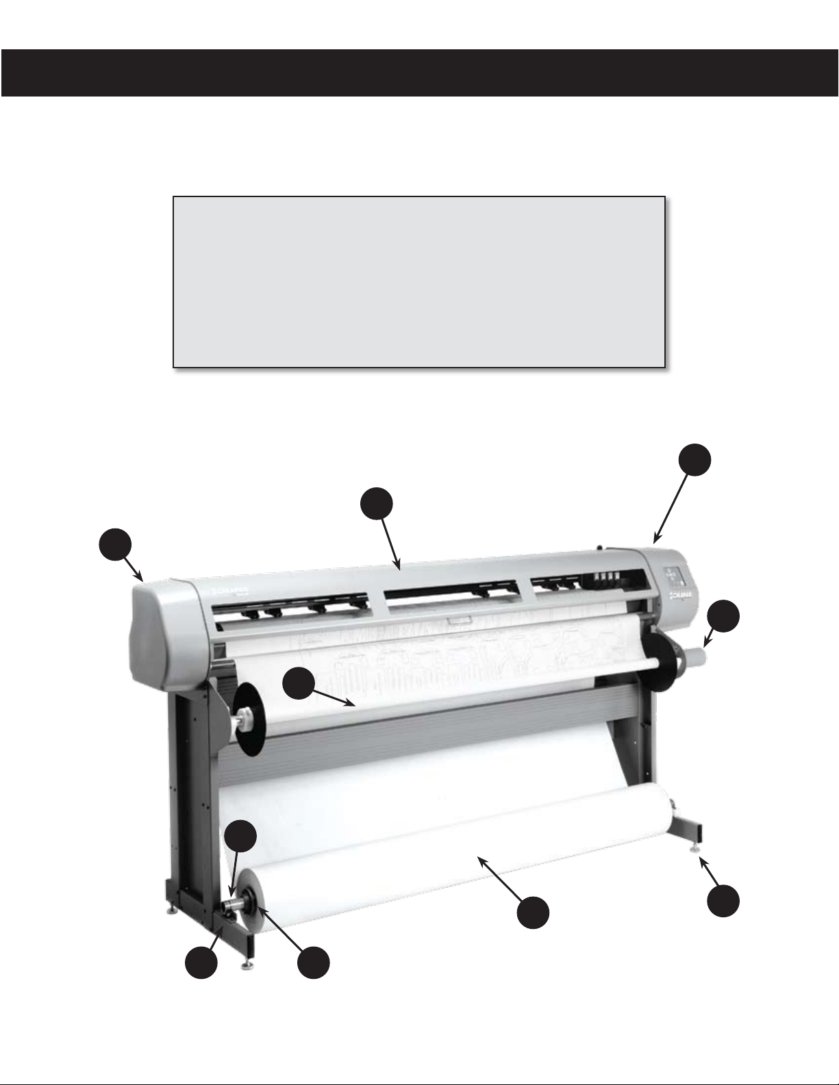
A
A. Left End Cover
B. Safety Cover
C. Right End Cover
D. Take-up Motor
E. Stand Leveling Foot
B
F. Feed Roll
G. Take-up Shaft
H. Paper Hub (2)
Feed Shaft
I.
J. Support Block (2)
C
D
G
I
J
Figure 2. The Ioline FlexJet Printer front view.
xvi
H
F
E
Visual Reference Guide
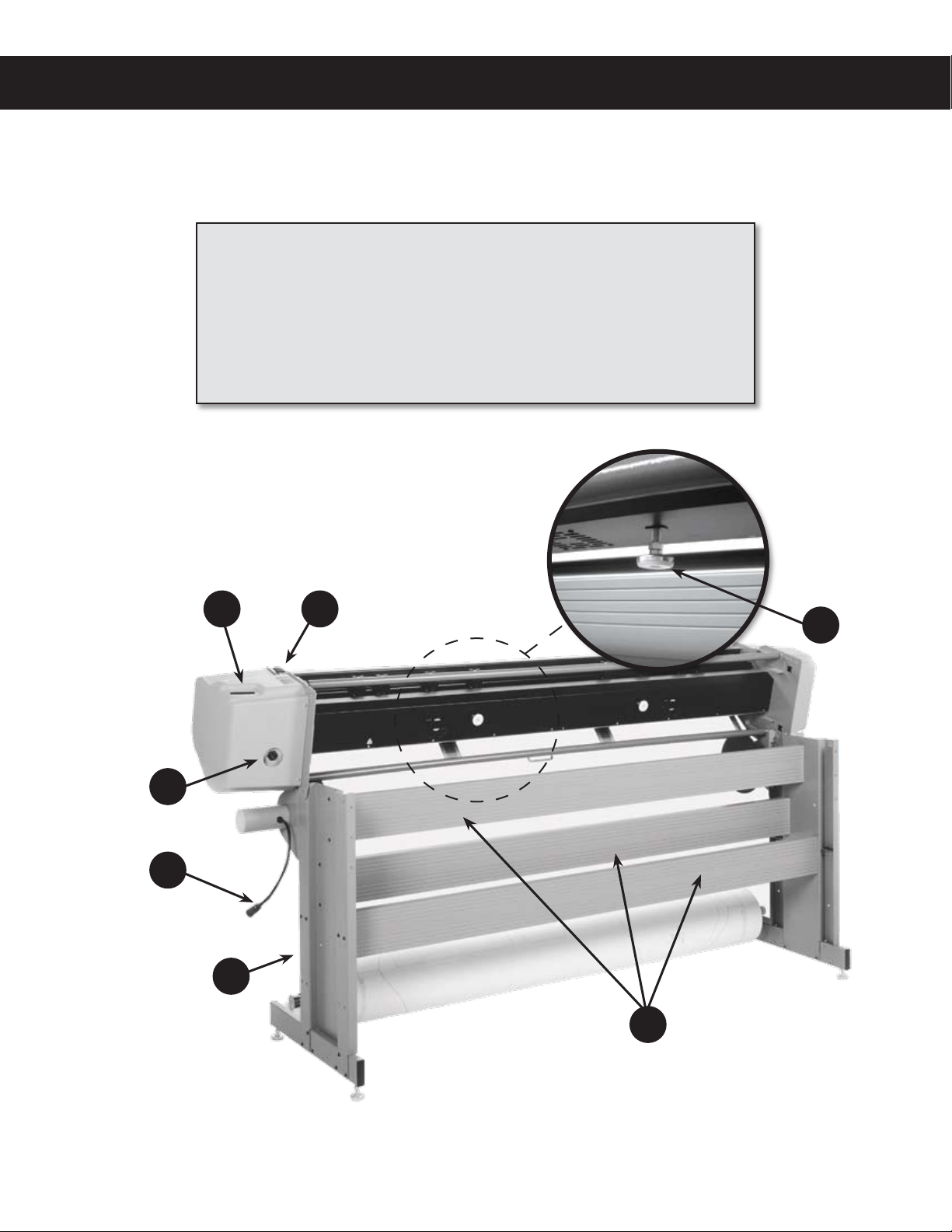
KEY
K. Stand Leg (2)
L. Take-up Motor Cable
M. Take-up Motor Outlet
N. Serial & USB Ports
N O
O. Power Switch and fuse
P. Platen Leveling Foot
Q. Cross-member (3)
P
M
L
K
Figure 3. The Ioline FlexJet Printer rear view (head tilted in maintenance position.)
Q
xvii
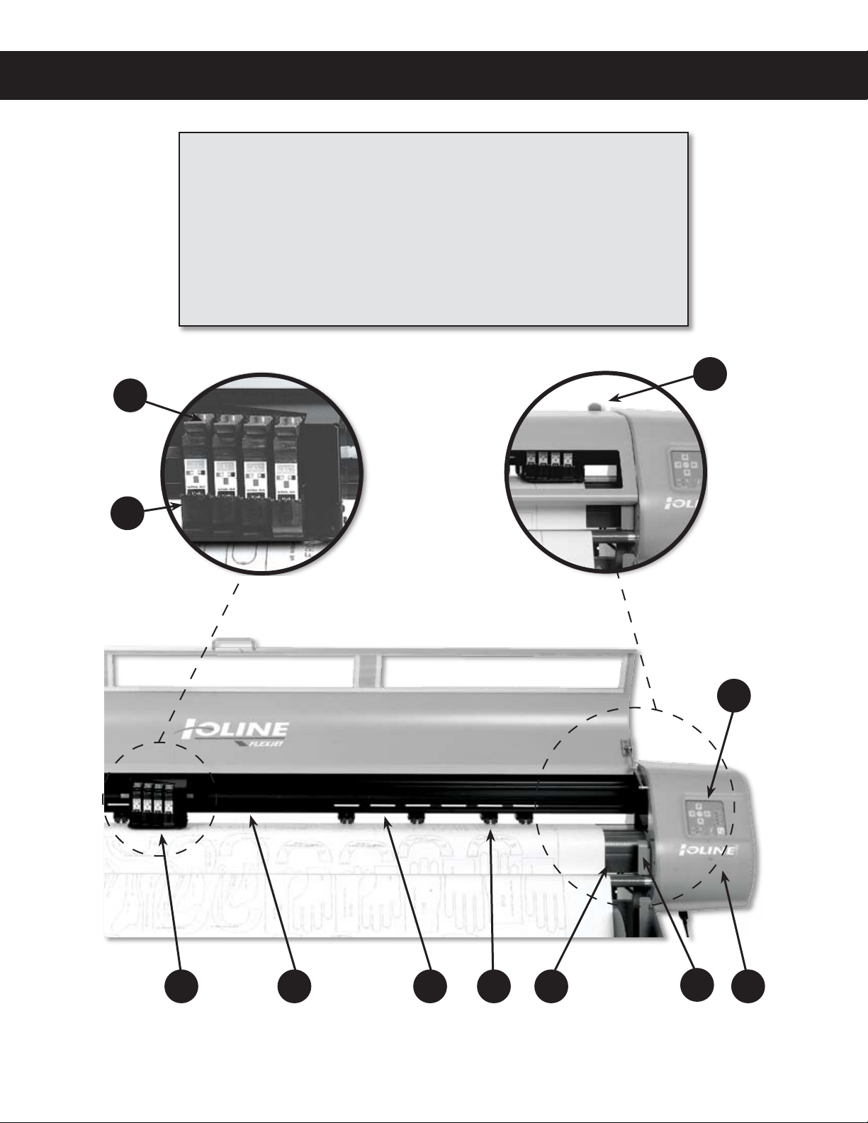
KEY
S
R
R. Ink Cartridge Stall
S. Cartridge Stall Latch
T. Pinchwheel Lever
U. Keypad
V. Service Station
(Beneath Cover)
W. Take-up Sensor
X. Platen
Y. Pinchwheel
Z. Drive Shaft Marker
aa. Traverse
ab. Carriage Assembly
T
ab aa
Figure 4. The Ioline FlexJet Printer front view close-up (safety cover lifted for clarity.)
Z
Y X
W
U
V
xviii
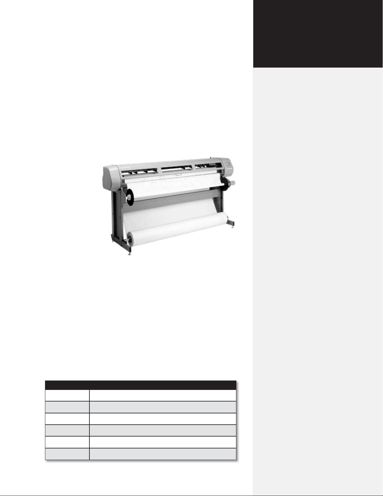
Product overview
The FlexJet is
most commonly
used in conjunction with popular
apparel software
for printing
marker patterns,
used in the manufacture of clothing. The FlexJet
also comes with
FlexPlot software that allows
printing of the
most popular
formats such as
AutoCad® (DXF),
CorelDraw!® (PLT),
Adobe® Illustrator® (DXF), Gerber® (STD, PLT or ASTM), Lectra®
(ASTM), Investronica® (ASTM).
Figure 5. The Ioline Flexjet.
Chapter 1
Overview
The Ioline FlexJet can handle many different printing operations
up to 72 inches wide and 600 yards long. Three industry standard
printer languages (HPGL 7475, and DM/PL) are supported.
The Ioline FlexJet also supports direct cable connection from many
popular programs such as PAD®, Scanvec® Optitex®, Polytropon®,
Ioline IPS software, and other applications.
Supported languages
Language Application
HPGL Direct from software or Ioline FlexPlot.
DM/PL Direct from software or Ioline FlexPlot.
DXF Ioline FlexPlot only.
STD Ioline FlexPlot only.
ASTM 6959 FlexPlot only.
Ioline syntax Direct special control characters for FlexJet.
20
Ioline FlexJet Service Manual
Specications
Metric Empirical
Max. plotting width 1.83 m 72-in
Media width
min.
max.
Marker length 548.6-m
Floor space requirements
Height
Width
Depth
Weight
Actual
Dimensional (US)
Dimensional (Int’l)
Paper type Recycled to bond
Feed roll position Front oor loading
Paper take-up roll position Ergonomic waist-level off-loading from front
Line thickness Thin, normal or thick
.91-m
1.88-m
(Unattended)
2.4-m x .7-m
1.2-m
2.4-m
.7-m
150 kg
190 kg
221 kg
36-in
74-in
600 yds
(Unattended)
96-in x 26-in
46-in
89-in
26-in
330 lbs
417 lbs
487 lbs
Resolution
Best mode:
Draft mode:
Ink cartridges Off-the-shelf
PC interface USB / Serial (RS-232)
Protocol HPGL / DM/PL
Languages DM/PL, DXF, HP-GL, HP-GL/2, MicroJet STD, ASTM
Compatibility
Power requirements 85-260 VAC, 0.25 KVA, Single phase, 47-440 Hz
Humidity Non-condensing
Warranty 1-year parts and labor
600 dpi
300 dpi
HP® 51645A cartridges
Gerber® (Accumark®, MicroMark®, and Micro-
dynamics®), Assyst®, AutoDesk® (AutoCAD®),
Investronica®, IPS, Lectra®, Scanvec® (Optitex®),
PAD®, Polygon®, Polytropon® (PolyPattern®), Vetigraph® and others
How the FlexJet works
The Ioline FlexJet combines paper and ink cartridge motion to create
vector outputs in a wide 72-in format. The data are sent to the FlexJet
via either a standard RS-232 serial or USB cable. When a le is sent to
the printer, the electronic system translates the vectors into instructions for the “X” (paper motion) and “Y” (Ink cartridge motion) motors. At the same time instructions are sent to the carriage assembly
to apply ink to the paper.
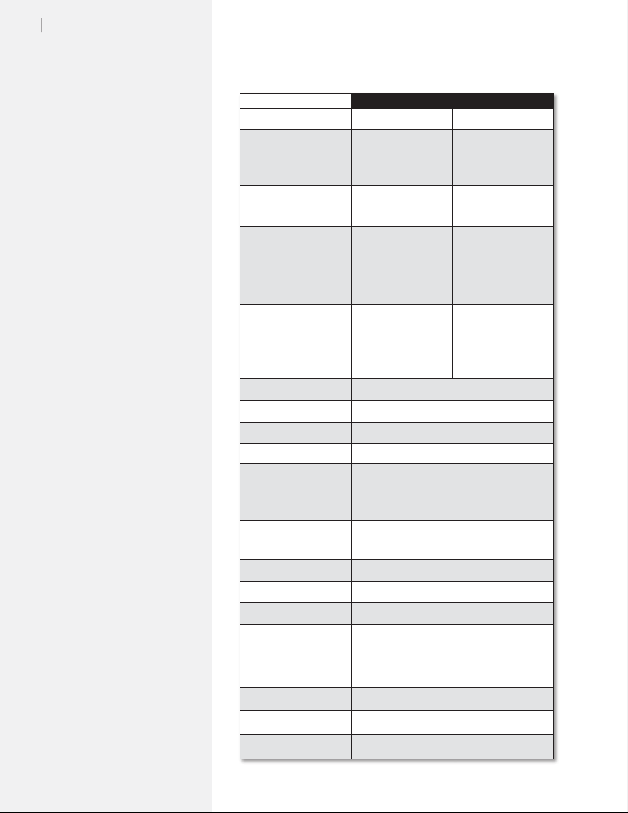
Paper movement
Paper motion is accomplished by pulling paper through the
machine with a traction shaft. The shaft is
connected to the X-axis
motor with a timing belt
transmisison assembly.
The drive-shaft rotates
in one direction.
Figure 6. Paper direction.
Chapter 1: Over view
21
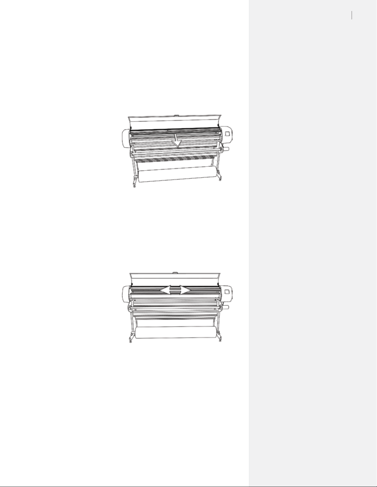
Carriage movement
The Y-Axis transmission powers a timing belt that transports a V
wheel carriage along the Y-Axis traverse extrusion. The ink cartridges are attached to the carriage and are made to apply ink to the paper
by actuating the electronics of the ink cartridge. When not printing,
the carriage assembly is stored in the FlexJet Service Station to keep
the ink cartridges clean and capped so they don’t dry out.
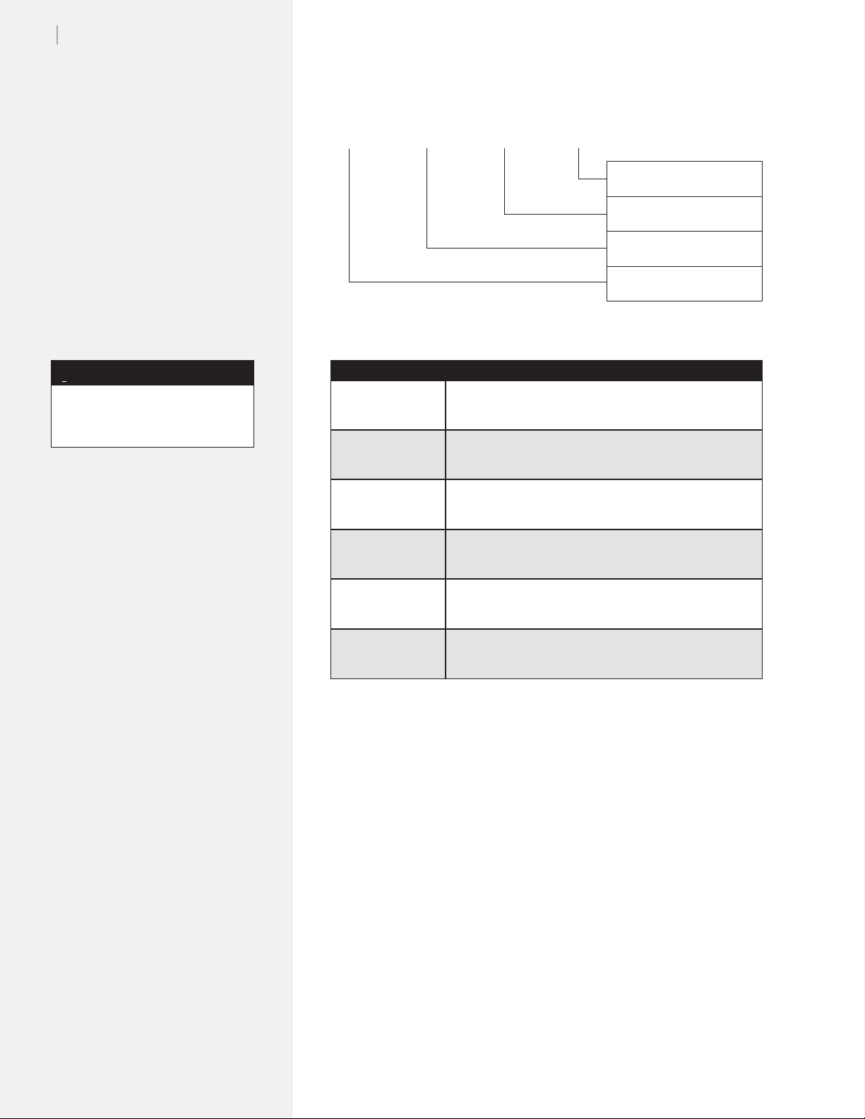
Serial number
identication
Identication of Ioline
Corporation products is
accomplished by use of
a serial number located
on the back of the right
side cover on the printer. You can determine
the model and date of
manufacture using the
following guidelines:
Figure 7. Carriage movement.
22
Ioline FlexJet Service Manual
FJ 03 26 01
{
Glossary
{
{
{
Number of machine manu-
factured in that week
Week of manufacture
Year of manufacture
Model number
i
An expanded Glossary is available
in the FlexJet User Guide.
Note
BOM Bill(s) of Material for Assembly
Bottom Pan Metal housing protecting the underside of the printer.
Carriage The component that holds the ink cartridges. It traveles
along the Y-Axis on the traverse assembly.
Keypad Where the user controls simple printer functions. Carriage
and media motion is accessible from here during stop
mode.
Traverse Assembly The structure that supports and guides the carriage as-
sembly.
X-Axis The direction of the paper moving through the machine.
Y-Axis The direction of the carriage moving back and forth.
Software setup options
Ioline recommends using FlexPlot for marker making on the
FlexJet. FlexPlot offers the most robust and exible workow
available for creating output. It’s especially useful when many le
formats are used, a common situation for service bureaus. To set-up
and learn how to use the software, see the FlexPlot User Guide.
The FlexJet is designed to work in many different production environments. The type of marker printing you do will often determine
your preferred communication method. Two typical methods for
sending markers are:
1. Plot directly from the marker or design software to the
FlexJet. (See Figure 8.)
Unlike other marker printers, the FlexJet is capable of operating
as a stand-alone device with no extra software running on the
computer. This method works if your CAD software includes
a driver for any Ioline product, such as the Ioline 600Ae or the
Summit 2200. It will also work if the CAD software can create a
compatible HPGL- or DM/PL- formatted le.
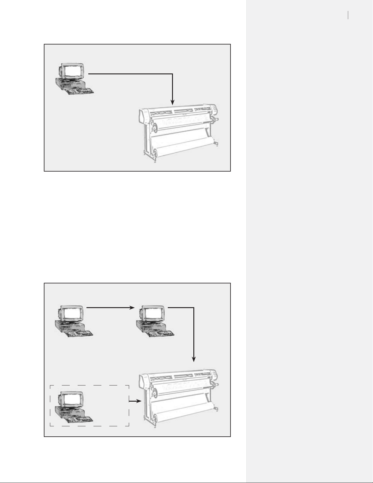
CAD
Software
HPGL
DM/PL
FlexJet
Figure 8. Workow: output direct from CAD software (without FlexPlot).
Chapter 1: Over view
23
2. Use FlexPlot software to convert les before sending them
to the FlexJet for output.
The FlexJet includes the FlexPlot software which will convert
many different les into a format that is compatible with the
FlexJet. It also provides an advanced marker queue management system and other tools to optimize the performance of the
printer.
CAD
Software
[Network]
FlexPlot
HPGL
DM/PL
DXF
ASTM 6959
STD
(Alternate Conguration)
CAD
Software
+
FlexPlot
FlexJet
Figure 9. Workow using FlexPlot for le conversion and output.

24
Ioline FlexJet Service Manual
Caution
Keep hands and loose
clothing away from all
moving parts of the
printer. Make sure the Service
Station opening in the right end
plate is not obstructed and that
the stall latches are lowered.
Power on
Turn on the computer and the printer to make sure they both work.
The printer power switch is located next to the power cord on the
back of the machine, behind the keypad. When the FlexJet is powered up, the carriage will move toward the left side of the machine,
then return to the opposite side to park in the Service Station. The
OK light will turn red and the Square light will turn green on the
front panel after the start-up process has nished.
Installing FlexPlot and
the Control Center
The FlexJet includes two software interfaces: FlexPlot and the
Control Center. FlexPlot will import and queue marker les from
many design programs to optimize production operations. The
Control Center is an interface for adjusting parameters to optimize
printer performance. The printer comes with a CD-ROM which has
Microsoft Windows® 98/2000/XP versions of the programs as well
as PDF user guides and the required Adobe® Acrobat® reader.
1. Power on the computer and Windows
®
.
2. Insert the Ioline CD-ROM into the CD-ROM drive (usually D:).
3. The installation program should start automatically. If it does
not:
a. Select the Start button.
b. Choose Run.
c. Type
4. Follow the instructions that appear on the screen.
5. The FlexPlot User Guide has details on using the FlexPlot software. In this manual, see the section The FlexJet Control Center
for more details about the Control Center software.
D:\IOSETUP (substitute the correct letter if the CD-
ROM drive letter is not D:) and Click OK.

Chapter 1: Over view
25
The FlexJet Control Center
Overview
The FlexJet Control Center is a utility program that does two things:
n Allows you to adjust settings to tailor output (e.g. scale, line
width) from the computer.
n Provides an interface to send completed les to the printer.
i
To avoid communication port
conicts, do not simultaneously
run more than one application
that communicates with the
printer.
Note
Figure 10. FlexJet Control Center main menu.
Changing system settings
A variety of settings are adjustable to t specic needs:
n Make sure the printer power is on and that the initialization
process is complete. The carriage will park, the keypad OK
light will turn red and the Square light will turn green.
n The Screen Menu displays the primary settings that are adjust-
able. The Menu Bar contains utilities for setting up the Control
Center and calibrating the FlexJet.
n Changes only take effect after one of the Send buttons is
pushed.

26
Ioline FlexJet Service Manual
Control Center menu bar features
File
Download Firmware Allows the user to download the lat-
est rmware version for the FlexJet.
See the FlexJet User Guide for more
information.
Send Plot File Print a PLT or PLX le.
Exit Exit the Control Center.
Communications
Settings Select the COM port and baud rate
to match the printer.
Send Command Permits advanced users to manually
enter commands.
Tools
Cartridge Calibration Displays tools to adjust print
cartridge alignment. See the FlexJet
User Guide for more details.
Reset Machine ID Resets the machine serial number.
A unique key code, only available
from Ioline customer service, is required. It is usually only necessary
if the main logic board is changed.
Size Calibration Allows adjustment of the size cali-
bration settings. See the FlexJet User
Guide for more details.
Set Machine ID Stores the printer serial number in
permanent memory. This step is
required for upgrading the number
of active print cartridges in machines
pre-wired for expansion.
Set Key Code Sets the license key code to enable
inactive print heads in machines prewired for expansion. It requires that
the serial number is stored in permanent memory with the Set Machine
ID function described above.
Help
About Displays Control Center version
information.

Control Center menu options
Software Version
Displays the current rmware version installed in the FlexJet.
Cartridge Count
Displays how many cartridges are in active use by the printer.
Get Plotter Data
Reads and displays the current settings stored in the FlexJet in the
input boxes.
Plotter Data (check box)
Indicates when the displayed settings were successfully downloaded
from the printer. If this box is unchecked, the Control Center was
unable to connect with the FlexJet and cannot display current settings.
Check the connections, baud rate and COM port. Press the Get Plotter
Data button to attempt to download settings if the process failed
during startup.
Chapter 1: Over view
27
Line Width
Controls the weight of the plotted line using line width. Three levels
are available; Thin, Normal, and Thick. Thin lines use less ink and
make ne details like Asian text and small pieces easier to see. Thick
lines use more ink to produce higher contrast lines.
Used in conjunction with the Quality Setting (see below), the FlexJet
provides six options for output quality, to enable you to produce
clearly visible lines using the least possible amount of ink.
Scale
The printer scale ranges from 1% to 999%. The factory default Scale
is 100%. A scale set to 50% prints at half size. Changes do not take
effect until the Set Scale button is pressed. Note: Both X- and Y-Axes
are set independently.
Frame Size
Most design software sends long plots to printers by breaking them
into smaller pieces called frames. In general, design software does this
automatically and adjusts the Frame Size in the printer to match.
The Frame Size setting establishes clipping limits for each data
frame. If the printed size of a plot frame exceeds the frame size set
in the FlexJet, the excess is clipped or thrown away. (If the plot is
clipped, try increasing the Frame Size manually.) The factory-set
X-axis (paper direction) frame size is 46-in (116.8-cm), maximum is
21600-in (54,864-cm). Default and maximum Y-axis (carriage direction) frame size is 72-in (182.9-cm).

28
Ioline FlexJet Service Manual
Quality Setting
Choose Draft or Best to control line density. Draft mode uses 300 DPI.
Best mode uses 600 DPI. A lower DPI setting uses less ink by creating
a fainter line. Higher DPI uses more ink but makes a darker line. Use
this setting in conjunction with the Line Width (see above) to nd a bal-
ance between saving ink and making clearly visible lines.
Measurement Units
Choose between English or Metric units for settings display.
Product components
Chapter 2
Nomenclature
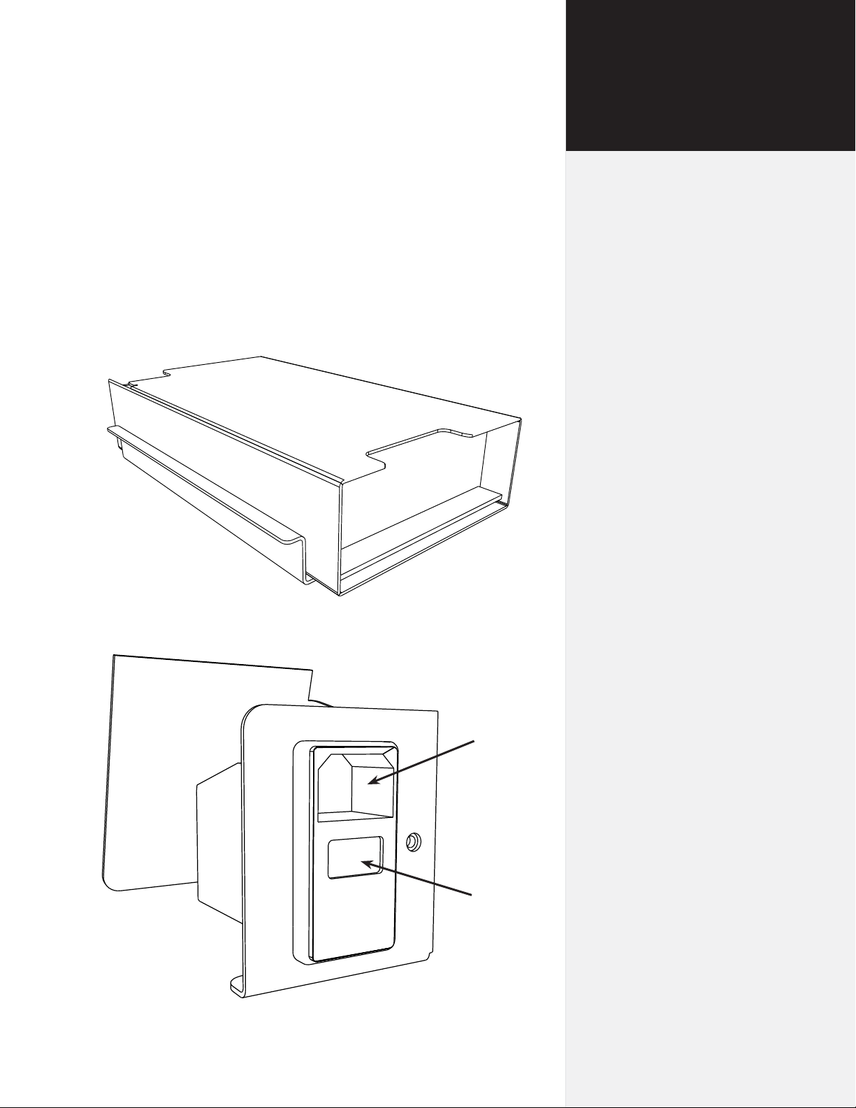
Figure 11. The Ioline Flexjet power supply.
Figure 12. Rear power panel assembly.
Power
cord
plugin
Power
switch
30
Ioline FlexJet Service Manual
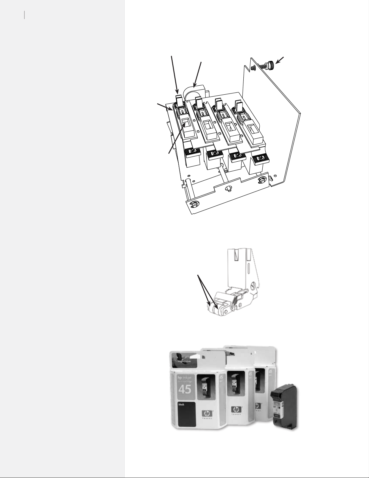
Cartridge
wipers
Cartridge
caps
Cartridge
“spit
wells”
Servo motor
Carriage stop
adjustment
screw
Figure 13. Service Station assembly.
Wheels
(Replaceable)
Figure 14. Pinchwheel assembly.
Figure 15. Ink cartridges: HP 51645A.
 Loading...