

Page 1

Copyright © 2000, Ioline Corporation, All Rights Reserved
Printed in the United States of America
PN 107027 R1
November, 2000
All Trademarks Are The Property Of Their Respective Owners
Using Your
Ae Apparel Plotter
Page 2
2
Ioline
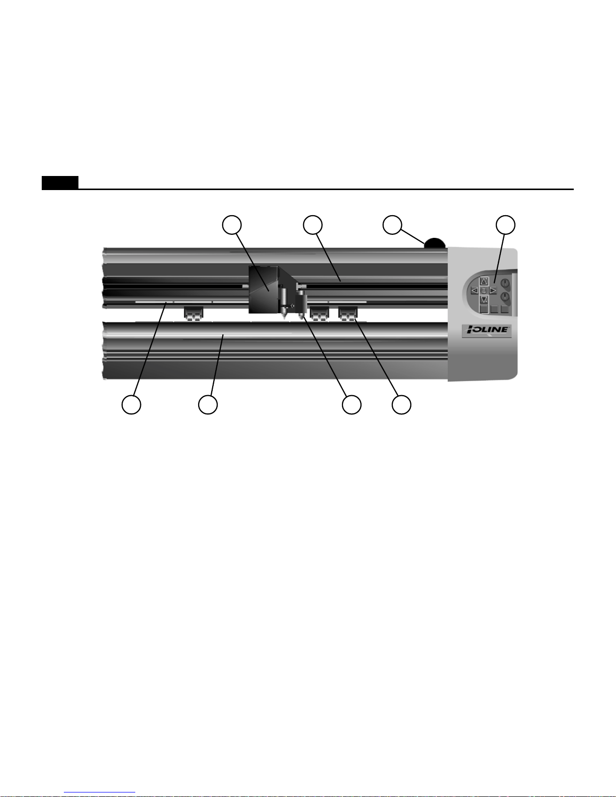
A. Pinchwheel
B. Drive Shaft Marker
C. Carriage
D. Platen
E. Sensor (600Ae only)
F. Carriage Rail
G. Pinchwheel Lever
H. Keypad
Figure 1. The Ioline Model 600Ae Plotter.
DB E
A
HG
F
C
Page 3

3
Ioline
TABLE OF CONTENTS
SAFETY AND PRECAUTIONS ................................ 4
THE IOLINE AE APPAREL PLOTTER .................... 4
How The Ioline Plotter Works .............................. 5
INSTALLATION ........................................................ 6
Unpack the Plotter .............................................. 6
Assemble the Stand ........................................... 6
Attach the Plotter to the Stand.............................6
Connect the Plotter to the Computer ................... 6
Power On ........................................................... 6
Installing the Ioline Control Center ....................... 6
OPERATION............................................................. 7
Keypad Controls .................................................. 7
The Ioline Control Center .................................... 9
Changing System Settings ............................... 10
Menu Bar Features........................................... 10
Screen Menu Options ....................................... 10
Plotting a Marker ................................................ 12
General Guidelines........................................... 12
Installing a Pen ................................................. 12
Power On ......................................................... 12
Paper ............................................................... 12
Guidelines for Plotting Pens.............................. 12
Loading the Feed Roll ...................................... 13
Loading the T ake-Up Shaft ............................... 14
Feeding Paper ................................................. 15
T aping Paper to the Take-Up Shaft.................... 16
T aping Paper (Optional Method) ....................... 17
Positioning the Pinchwheels ............................. 17
Insert the Dancer Bars ...................................... 18
Set an Origin .................................................... 18
Sending Plot Files ............................................ 19
Pausing a Marker Plot ...................................... 19
Canceling a Marker Plot ................................... 19
Removing Markers from the T ake-Up Shaft ....... 20
Reattach Paper to the T ake-Up Shaft ................ 21
ROUTINE MAINTENANCE .................................... 22
Cleaning the Drive Shaft ................................... 22
Calibration........................................................ 22
Cleaning the Platen .......................................... 23
Cleaning the Support Blocks............................. 23
COMMUNICA TION TESTING.................................24
Communication T est ......................................... 24
T esting the Plotter Serial Port............................24
T esting the Computer Serial Port ...................... 24
TROUBLESHOOTING ........................................... 25
General Problems ............................................ 25
Plotting Quality Problems.................................. 25
Loss of Registration Between Frames .............. 27
Tracking ........................................................... 27
Poor Line Quality .............................................. 27
Error Messages................................................ 28
LED Codes ...................................................... 29
T esting the Frame Sensor................................. 30
END NOTES ........................................................... 31
Getting Help ..................................................... 31
The FCC Wants Y ou to Know ... ......................... 32
Y our Comments Are Requested........................ 32
Customer Service............................................. 32
Limit of Liability Statement................................ 32
GLOSSARY ............................................................ 33
INDEX ..................................................................... 35
Page 4

4
Ioline
SAFETY AND PRECAUTIONS
The plotter has many fast moving components. Please read and follow these
safety guidelines before beginning operation of the plotter.
• Do not try to repair the machine without factory authorization. Only qualified service personnel should attempt any disassembly or access to internal components. If external mechanical adjustments are necessary, turn
off the plotter and disconnect it from all power sources (both the computer and the wall outlet).
• Be careful with hair, jewelry, or loose clothing near the plotter. They can
become caught in the mechanical parts.
• Never move the carriage by hand. Use the Arrow keys and let the machine do it.
• Keep hands away from the carriage when the plotter is in operation. The
carriage will automatically move to its right end position when the power
is turned on.
• Be careful when lifting the plotter. Hold the bottom surfaces of the plotter
to lift or move it.
• Keep fingers away from the drive shaft when the plotter is in operation.
THE IOLINE AE APPAREL PLOTTER
Thank you for purchasing an Ioline plotter.
This manual contains instructions and guidelines for setting up, operating
and maintaining the Ioline plotter models 600Ae, 28Ae and Stylist Ae. The
model 600Ae uses a frame sensor to allow ultra long plotting up to 600 yards.
Models 28Ae and Stylist Ae do not use a sensor for frame correction which
limits plotting to 42 yards. The following components are needed to create
plots:
• An Ioline plotter that is installed according to the directions in the Quick
Start Guide.
• A computer system that is properly installed and has a functioning serial
port.
• Design software loaded into the computer according to the installation
instructions. Note: The design software must output plot files in HPGL
7475/7596 or DM/PL format.
• Plotting media and a pen that are within the guidelines stated in the
Operation chapter.
• The Ioline Control Center software. This software is not required but
allows adjustment of plotter settings and can help optimize performance.
The Ioline Control Center will only run on the Windo ws 95/98/NT oper ating systems. Most design software provides drivers for Ioline plotters.
Contact Ioline customer service if you need assistance with drivers.
Page 5
5
Ioline
How The Ioline Plotter Works
Media and pen motion are combined to create vector plots. Files are sent to the plotter via a serial connection with a computer or file server . When a file is sent to the plotter
the electronic logic system translates the vectors into instructions for the X axis (paper motion) and Y axis (pen motion) motors and uses feedback to ensure plot accuracy.
Long plots are accomplished by breaking the plot file into frame segments and rolling the completed frames onto a take-up shaft. The model 600Ae can roll 600 yards onto
the take-up shaft in one plotting sequence. The 28Ae and Stylist Ae can create a mark er no longer than 42 yards b ut can accumulate 100 yards from multiple plot f iles on the
take-up shaft. Long plot accuracy on the 600Ae is maintained by checking an alignment mark on each frame with multiple passes of a sensor fixed to the carriage.
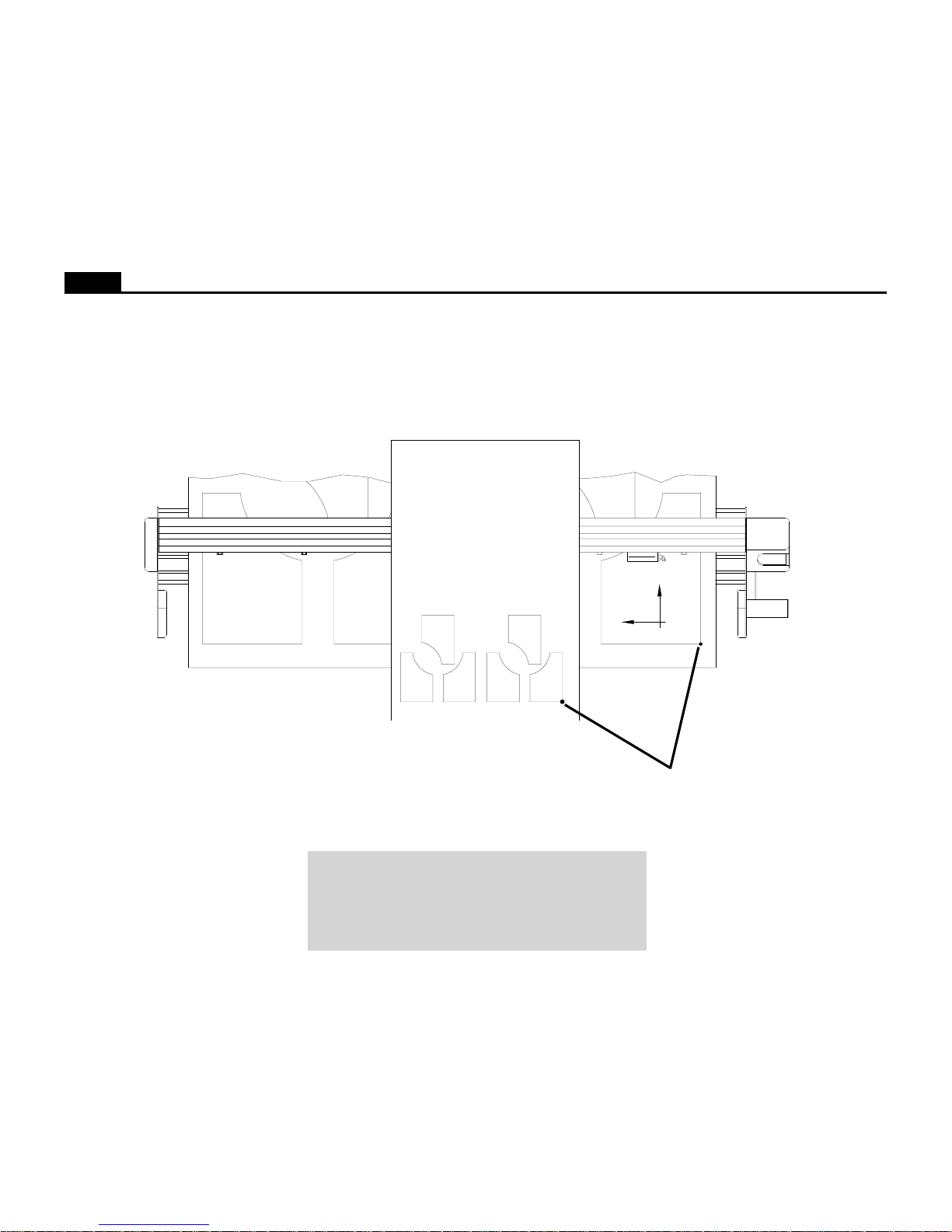
Figure 2. The X and Y axes and Origin (top view).
Note: In this manual the right and left side refers to the right and left
side of the front of the plotter. Design software usually refers to the
Origin (or Start Point) as “lower left” because it is the lower left
corner of a plot. The plot is usually oriented in the plotter rotated 90
degrees counter clockwise as shown in Figure 2. The lower left cor-
ner of the plot is physically on the right side of the plotter.
LEFT EDGE OF PLOT
LOWER EDGE OF PLOT
Y
X
Left Side
of Plotter
Right Side
of Plotter
Origin at Right
Side of Plotter and
Lower Left on Plot
Page 6

6
Ioline
INSTALLATION
The complete setup procedure for Ioline Ae plotters is described in detail in
the Quick Start Guide included with the accessory kit. The following infor-
mation is a brief summary.
Unpack the Plotter
Carefully remove the plotter from the box and place it on a flat-stable surface.
This procedure requires two people. Save all packing materials and the box.
Check the packing list to ensure that all of the accessories are present. See the
Quick Start Guide for more information.
Assemble the Stand
Assemble and level the stand using the hardware included in the accessory kit
and directions outlined in the Quick Start Guide.
Attach the Plotter to the Stand
Caution: Do not hold the plotting head by the bottom edge of the
end plates when attaching it to the stand. Fingers and hands might
get pinched between the end plates and stand legs. Hold the shiny
metal top bars a few inches from the end plates when handling the
head.
Attach the plotter to the stand with the top bars resting in the notches in the
stand legs. Use the hardware as indicated in the Quick Start Guide.
Connect the Plotter to the Computer
Note: Make sure the computer and the plotter have the power turned
off. Ioline recommends using a surge protector power strip for the
plotter and the computer.
Connect the plotter to the computer with a serial cable. A serial cable is provided in the accessory kit. The serial port on the computer is either a 9 pin or
25 pin male receptacle. If the computer only has 9 pin serial ports, a 9 to 25
pin adapter is necessary. Use the adaptors included in the accessory kit. See
the Quick Start Guide for more connection information.
Select the correct port in the design software or the Control Center after the
cables are correctly connected to the computer and plotter. Consult the design
software manual or the dealer for further information.
Power On
Important: Keep hands and loose clothing away from all moving
parts of the plotter.
Turn on the computer and the plotter to make sure they work. The plotter
power switch is located next to the power cord on the back of the machine,
behind the keypad. The carriage will move toward the keypad side of the
machine when the power is turned on. The red LED on the front panel will
light when the start-up process is finished.
Installing the Ioline Control Center
The Control Center is an interface for adjusting parameters to optimize plotter performance. The plotter comes with a CD-ROM which has the Microsoft
Windows® 95, 98 and NT (3.51 or greater) version of the Ioline Control Center
program.
1. Turn on the power to the computer.
2. Start Windows®.
3. Insert the Ioline CD-ROM into the CD-ROM drive (usually D:).
4. The installation program should start automatically. If it does not:
a. Select the Start button.
b. Choose Run.
c. Type D:\IOSETUP (substitute the cor rect letter if the CD-ROM dri ve
letter is not D:) and Click OK.
5. Follow the instructions that appear on the screen.
6. The Operation chapter of this manual has details on using the Ioline
Control Center software.
Page 7
7
Ioline
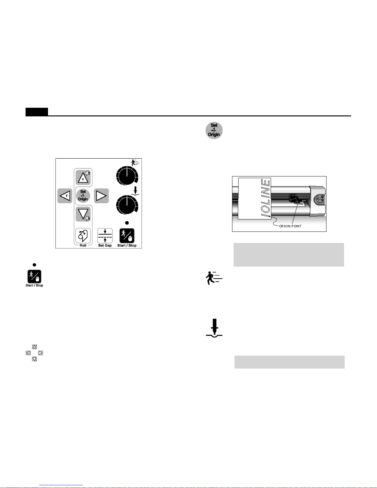
Figure 3. The Plotter Keypad.
OPERATION
KEYPAD CONTROLS
The keypad allows access to the main plotter functions.
Start/Stop
The Start/Stop key controls communication between the computer and the plotter. If the Start/Stop key is pressed dur ing plotting (Stop mode, red LED) the machine will stop plotting when
the current vector is finished. The Arrow keys are active when in
Stop mode. When the Start/Stop key is pressed again, (Start mode,
green LED) plotting will resume exactly where it stopped.
ST ART green light Arrow keys inoperable, plotter
online (ready to receive instructions).
STOP red light Arrow keys operable, plotter offline
(not ready to receive instructions).
Arrow Keys
Pressing the Arrow keys moves the material back and forth or the
carriage from side to side. The arrow keys will not w ork unless the
plotter is in Stop mode (see Start/Stop above).
Set Origin
The Set Origin key sets the initial origin or starting position for
the marker. It is best to set a ne w origin before plotting each marker .
To set a new origin, press Start/Stop until the keypad LED is red
(Stop mode). Use the Arrow keys to move the pen to the desired
origin of the plot. Press the Set Origin key. The plotter will then
accept plot files.
Speed
Use the Speed knob on the front panel of the plotter to adjust the
speed. Turn the knob clockwise to increase the speed, or counterclockwise to decrease the speed. Set the speed according to the
type of plotting and material being used. See the Plotting a Marker
section of this manual.
Force
Adjust the force by using the Force knob on the front panel. Turn
the Force knob clockwise to increase the force exerted on the pen.
See the section on Plotting a Marker for the recommended settings. The range of force available at the knob is adjustable in the
Control Center. The available range is 1 - 275 grams.
Note: Using too much force can cause excessive drag
which could damage the pen or tear the paper.
Figure 4. Origin Point.
Note: Design software usually refers to the origin as “lower
left” because it is the lower left corner of a marker. Because the plot is usually oriented as shown, it is physically on the right side of the plotter.
Page 8

8
Ioline
Set Gap
The Set Gap button allows the user to manually adjust the amount
that the plotter will compensate for the normal slipping (frame
gap) that occurs during frame advances. The frame gap distance is
primarily affected by the size of the feed roll, paper type, and
humidity. The advantage of using the Set Gap button to adjust
frame gap the ability to correct gapping during plotting. Frame
gap is also adjustable from the Control Center. The Set Gap button has additional functions on the 600Ae.
Setting the Frame Gap with the Set Gap button:
Note for 600Ae: This function only works when the frame
sensor is disabled in the Control Center. See the section
Sensor Options above for more details.
1. Prepare the plotter to receive a plot file. See the section Pre-
pare to Plot for more details.
2. Send a plot file to the plotter that has at least three frames.
3. After the second frame starts plotting, press the Set Gap button. The plotter will move the carriage and material to the
center of the last horizontal mark made at the beginning of
the second frame.
4. Move the material with the vertical Arrow keys until the pen
is over the middle of the horizontal mark made at the end of
the first frame.
5. Press the Set Gap button to resume plotting with the new
frame gap setting. The keypad LED should turn green. The
frame gap setting will not take affect until the current frame is
complete.
6. Visually check the gap setting by checking for a gap or overlap between the second and third frame.
7. This process is accessible anytime during plotting. The plotter will finish a frame advance cycle before recognizing that
the Start/Stop button was pressed.
Note: The Set Gap measurement is lost when the power
to the plotter is turned off.
Additional Set Gap button functions on the 600Ae:
Note: These functions only work when the frame sensor
is enabled in the Control Center. See the section Sensor
Options above for more details.
• Sensor Test (not available during plotting):
1. Load the plotter with paper. See Prepare to Plot for details.
2. Press the Start/Stop button until the keypad LED turns red
(Stop mode).
3. Use the keypad Arrow keys to position the carriage so that
the pen is over the paper near the right side of the machine.
4. Press the Set Gap button.
5. The plotter will draw a frame alignment mark and continu-
ously scan the mark until the Start/Stop button is pressed
again. If the sensor finds the mark it will beep. This function is
useful for adjusting sensor height.
6. If no beep is heard the sensor might need adjustment, cannot
sense the ink color in use, or is defective. Use black ink or
contact the distributor or Ioline Customer Service for details.
• Find Lost Sensor Mark:
Material slippage may cause the frame alignment mark to
move beyond the area where the frame sensor looks for it. If
the plotter is unable to find the mark with the frame sensor it
will enter lost mark mode. The keypad LED will turn solid
green and the plotter will emit a continuous beeping sound.
If this error occurs before the frame advance:
1. Check that the pen is drawing dark lines. Red ink will not
work with the sensor. Replace the pen if the mar k is very light.
2. If the lines are dark, help the plotter find the mark by positioning the carriage using the horizontal Arrow keys. Move the
carriage so the mark is lined up with the frame sensor in the
direction of paper movement (X). The plotter disables material (X) movement so the vertical Arrow k e ys will not w ork.
3. Press the Set Gap button. The plotter will look for the mark
and, if it finds it, will continue plotting.
4. Pressing the Start/Stop button will cancel lost mark mode,
ignore the missing mark, and continue with the previously
stored alignment correction measurement.
Page 9
9
Ioline
THE IOLINE CONTROL CENTER
The Ioline Control Center is a utility program that does three things:
• Allows adjustment of settings to tailor output from the computer.
• Provides an interface to send completed plot files to the plotter.
• Includes several diagnostic tests for troubleshooting.
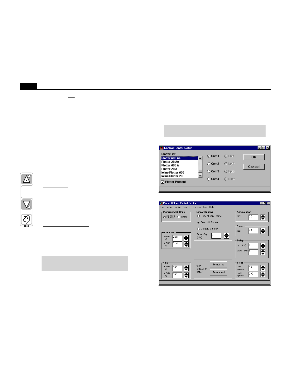
Figure 5. Control Center Setup Screen.
Note: T o a void communication port conflicts, do not simultaneously
run more than one application that communicates with the plotter.
Figure 6. Control Center Main Menu (model 600Ae shown).
If this error occurs after the frame advance:
1. Check that the pen has ink and is drawing dark lines. Higher
force may darken the line. Red ink will not work with the
frame sensor. Replace the pen if the sensor lines are very light.
2. If the lines are dark, help the plotter find the mark by positioning the material with the vertical Arrow keys so that the mark
is ½ inch below (in front of) the frame sensor. The plotter
disables carriage (Y) movement so the horizontal Arrow keys
will not work.
3. Press the Set Gap button. The plotter will look for the mark
and, if it finds it, will continue plotting.
4. Pressing the Start/Stop button will cancel lost mark mode,
ignore the missing mark, and continue with the previously
stored alignment correction measurement.
Roll
The Roll keys are used to rotate the take-up shaft.
Roll Up Material – Press the Start/Stop button until the keypad light is red. Press and hold the Roll button and the Up
Keypad Arrow. The plotter will pull paper onto the take-up
roll until the end of the service loop is reached.
Unroll Material – Press the Start/Stop button until the keypad light is red. Press and hold the Roll button and the Down
Keypad Arrow. The plotter will unroll paper from the takeup roll onto the floor until the keys are released.
Automatic Unroll (600Ae only) – Press the Start/Stop button
until the keypad light is red. Press and hold the Roll button
and the Down Keypad Arro w. W ith the other hand, press and
release the Up Keypad Arrow. Stop pressing all b uttons. The
plotter will automatically unroll paper for one minute then
stop. To cancel automatic mode, press the Start/Stop or any
Arrow key.
Note: For more details on removing plotted markers from
the take-up shaft see Removing Markers from the TakeUp Roll later in this chapter.
Page 10

10
Ioline
Changing System Settings
A variety of settings are adjustable to fit specific needs:
• The plotter must be in Start mode (green LED on) when changing system settings. Press the Start/Stop key and make sure the green light is on
before changing any settings.
• The Screen Menu displays the primary settings that are adjustable. The
Menu Bar contains utilities and less common plotter settings.
• The selected changes will be in effect only after one of the Send Settings
buttons is pushed.
Note: Some design software can override the Control Center settings. Check to see if it has by pressing the Update Display button
before and after a plot is completed. If the settings change, use the
design software to modify plotting parameters.
Menu Bar Features
The Ioline Control Center provides comprehensive help files to explain the
functions of the software options. Below is a brief summary Menu Bar items.
File
Send Cut/Plot File Send a plot (.plt) file to the plotter.
Open Settings File Restores saved settings files.
Save Settings As Allows user to save settings f iles.
Exit Exits the Control Center program.
Setup
Plotter Setup Allows user to select the correct plotter model.
Port Setup Allows user to select the communications port.
Display
Plotter Settings Allows user to view current plotter settings.
Factory Defaults
Allows user to view and restore original factory settings.
ROM Version Displays installed ROM version.
Memory Buffer Displays installed memory b uffer size.
Options
HPGL Setting Allows user to select HGPL language.
Install New Firmware
Installs new firmware into the plotter.
Calibrate
Calibrate Plotter Allows user to calibrate plotter.
Test
Communication Test Allows user to test communications.
Computer Port T est Allows user to test computer port.
Plotter Port Test Allows user to test plotter port.
Help
Contents Lists contents of help files.
About Provides Control Center version information.
Screen Menu Options
Measurement Units
English or Metric units are available when adjusting settings.
Panel Size
The Panel Size is the maximum area the plotter can use for plotting before
advancing the paper . In general, set it to the same value as the design software
frame size (sometimes called panel, frame, tile, page, etc.).
Important: Never set the plotter panel size smaller than the software frame size; the plot will clip and the plotter may jam or tear
paper. Plotting with the plotter panel size set larger than the design
software frame size will make the plot the correct size but will make
the feed and take-up loops unnecessarily long.
The factory set (and maximum) X-axis panel length is 46 inches (116.8 cm)
long. The maximum Y-axis panel width is 72 inches (182.9 cm) wide. Note:
The material moves along the X-axis; the carriage moves along the Y-axis.
Scale
The factory-set Scale is 100%. The plotter will produce a plot in the exact size
of any plot file that is sent. If the scale is 50%, the plotter will produce a plot
that is half the intended size. The scale of the plotter can range from 1% to
999%. Note: Both X and Y axes are set independently.
Sensor Options (model 600Ae only)
Sensor Options control how the model 600Ae plotter uses the sensor to correct normal paper slipping during frame advance. Paper characteristics and
humidity are a few of the factors that affect slipping. Scanning e very frame is
useful for difficult materials. On high quality paper , Checking e very 4th frame
will increase throughput without compromising frame alignment.
Check Every Frame – When this option is checked the plotter uses the frame
sensor to check the alignment mark during every frame advance. This is the
most accurate but the slowest way to use the sensor during plotting. This
mode may also improve performance when plotting on materials that slip
when pulled off of the feed roll.
Every 4th Frame – When this option is checked the plotter uses the frame
sensor to check the alignment mark during every 4th frame advance. This
mode is less accurate than checking after every frame but increases throughput by an average of 10%.
Disable Sensor – Disables the frame sensor. Set the Frame Gap during plotting with the Set Gap keypad button (see the Keypad section) or manually
before plotting in the Control Center (see the Frame Alignment section).
Page 11

11
Ioline
Frame Gap (Alignment)
Setting the Frame Gap compensates for the normal gap/overlap that occurs
between frames during frame advance. Use a Frame Gap setting on the 28Ae
and Stylist Ae or on the 600Ae when the sensor is disabled (see above).
Note: Frame gap is also adjustable during plotting with the Set Gap
button on the keypad. Only use the following procedure to adjust
frame gap when the plotter is not plotting markers.
1. Prepare the plotter to receive a plot file. See the section Plotting a Marker
for more details.
2. Send a plot file to the plotter that has at least three frames.
3. When the plot is complete, use a ruler to accurately measure the gap or
overlap between the solid and dashed lines between he second and third
frames.
4. Set an origin on the plotter by pressing the Set Origin button. Make sure
the keypad LED is green (Start mode).
5. Start the Ioline Control Center program.
6. If the frames are separated enter the measurement as a negative number in
the frame gap field. For overlapping enter the measurement as a positive
number in the frame gap field.
Example: If the plot shows an overlap of .200 inches, set the frame
gap in the Control Center to 200 (positive). If the plot shows a gap of
.200, set the frame gap in the Control Center to -200 (negative).
7. Press Send Permanent in the Control Center to send the value to the
plotter.
8. Perform test plots to verify that the gap setting is correct. Repeat if necessary.
Send Settings to Plotter: Temporary
After changing any setting, the changes must be sent to the plotter. If Send
Settings to Plotter: Temporary is selected, all of the displayed settings will
be used for the current session. When the plotter is turned off these settings
will be lost and the previous permanent settings will be in effect when the
plotter is turned on again. If any settings are changed, repeat the Test Plot
procedure to ensure that the results are satisfactory.
Send Settings to Plotter: Permanent
If Send Settings to Plotter: Permanent is selected, all of the displayed settings will be sent to the plotter and will be saved for all subsequent sessions,
even after turning off the plotter.
Acceleration
The factory set acceleration is 2.0 g. The acceleration setting determines how
quickly the pen will reach full speed when starting or ending a plot line. Use
the Control Center to change the setting within a range of 0.1 to 2.0 g. Use
lower acceleration settings when trying to achieve maximum accuracy.
Speed
Speed refers to pen and media speeds during plotting. Lower speed settings
will improve the line quality but will reduce throughput. The factory default
speed is 30 ips (inches per second) or 76 cm/sec on the 600Ae and 20 ips
(inches per second) or 51 cm/sec on the 28Ae and Stylist Ae. The setting range
is 1 to 30 ips (2.5-76 cm/sec) on the 600Ae and 1 to 20 ips (2.5-51 cm/sec) on
the 28Ae and Stylist Ae.
Up/Down Delays
The factory set up and down delays are both 0 milliseconds (ms) or 0 thousandths of a second. The delay setting controls the amount of time, in milliseconds, the plotter pauses after lifting or lowering the pen. Under normal
circumstances this setting will not require adjustment.
Force
The minimum and maximum force settings for the Force control knob on the
keypad is adjustable. The factory set and default minimum is 10 grams. The
maximum value is 275 grams. The default maximum force is 200 grams.
Page 12
12
Ioline
PLOTTING A MARKER
Before plotting a marker, turn the plotter on, load it with paper, install a pen,
and set an origin. These steps are outlined below. In most cases the design
files are sent directly from the design software to the plotter. If necessary, use
the Ioline Control Center software to send design files, adjust settings and
test plotter communication.
General Guidelines
1. Good paper loading makes good plots. Please see the following sections
about properly loading paper.
2. Do not set the plotter panel size smaller than the software frame size; the
plot will clip and the plotter may jam or tear paper.
3. Use only enough force to make a clear line. Excessive pen force might
cause misalignment problems over the range of a long plot or tear the
paper.
4. Enable the frame sensor on the 600Ae plotters to ensure accuracy over
long markers.
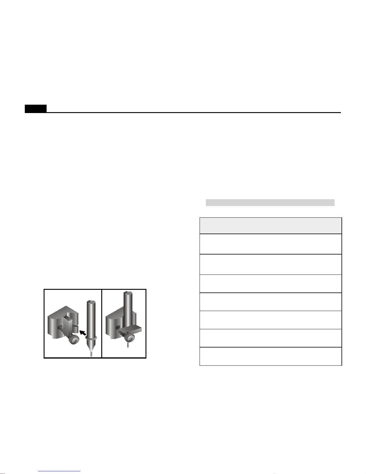
Installing a Pen
1. Rotate the clamp screw until there is enough room to insert the pen.
Make sure that the clamp is rotated up out of the way.
2. If using a plotter pen, slip the flange into the slot in the carriage jaw. If
using a regular pen, position the tip so that it is 1/8 inch (3 mm) off of the
platen when the jaw is in the up position. The jaw can hold any pen with
a maximum barrel diameter of 7/8 inch (22 mm). Do not use pens with red
ink.
3. Tighten the clamp screw until the pen is secure.
Power On
Turn on power to the computer and the plotter. The plotter power switch is
located next to the power cord on the back. The carriage will mo ve to the right
end plate when the power comes on. Keep hands and loose clothing away
from moving parts. The front panel light will turn red when plotter is ready.
Paper
Ioline recommends 27 - 35 pound recycled or bond paper, 36” to 74” (91 to
188 cm) wide.
Guidelines for Plotting Pens
Refer to the table below for recommended settings for a variety of pen types.
Remember that force values are for starting reference only and require testing.
Figure 7. Installing a Pen in the Carriage Jaw.
repaP neP deepS ecroF
smarg
stnemmoC
-yaLrepuSIMB
tnelaviuqero™talF
dnobytilauqhgih
elyts-PH
tniopllab
mumixaM08-06/punepsm51
nepsm51
syalednwod
"dnuoR®CIB
citS
tniopllab
mumixaM002-081
"drofnaS
eiprahS
mumixaM001-07
"elyts-PH
pitrebif
muideM001-07
___pitcitsalP______toN
dednemmoceR
___pitcimareC______toN
dednemmoceR
___/knidiuqiL
pitlateM
______toN
dednemmoceR
Important Note: Do not use red ink pens.
Page 13

13
Ioline
Loading the Feed Roll
1. Before loading a new paper roll always make sure the drive shaft is clean.
See the Preventative Maintenance section in the user guide for more
details.
2. Place a paper hub in each end of the paper roll. Use a rubber mallet to
insert the hubs.
3. Slide the feed shaft through the paper hubs and the paper roll. If a paper
hub falls out, press it firmly back into the end of the paper roll and set it
with a rubber mallet.
Figure 8. Installing the feed shaft.
4. This step is very important. Center the paper roll on the feed shaft by
sliding the feed shaft left or right through the paper roll. Make sure the
hubs remain securely in place.
5. Use the supplied hex wrench to tighten both screws on each paper hub.
6. Lift the feed shaft and paper roll into the support blocks. Make sure the
paper unrolls from behind and towards the plotter.
Support Block
Feed Shaft
Paper Roll
(Unrolls from Behind)
Paper Hub (2)
Flanged Coupling
Support Block
Page 14

14
Ioline
Loading the Take-Up Shaft
Caution: Never touch the take-up key or flanged coupling while
they are rotating. Serious personal injury could result.
1. Turn on power to the plotter.
2. If the take-up shaft has plotted markers on it, remove them. See Unload-
ing Completed Markers later in this section for details.
3. Rotate the take-up key with the Roll arrow keys until it is oriented perpendicular to the support block opening as shown below.
4. If rolling up more than 42 yards on the take-up shaft (model 600Ae only),
install the paper guide flanges. Make sure the hub with the thumbscrew is
on the outside of the flange.
5. Put the take-up shaft into the front support blocks with the flanged coupling at the right (keypad) end.
6. Rotate the shaft until the slot in the flanged coupling is aligned with the
take-up key. When the shaft slot and the key are aligned, push the takeup shaft into place until it is seated in the support block.
Figure 9. Installing the take-up shaft in the support blocks.
Position Take-Up
Key as Shown
Rectangular Slot
Support Block
Paper Guide Flange
with Hub Facing Out
Take-Up Shaft
Flanged Coupling
Page 15

15
Ioline
Feeding Paper
The figure below represents the proper paper paths. The diagram on the left
shows the paper after it is inserted properly and taped to the take-up shaft. The
figure on the right shows the result after the dancer bars are inserted and an
origin is set with the Set Origin keypad button.
1. On the model 600Ae, slide each of the paper guide flanges toward the
outside ends of the take-up shaft to create enough room for the width of
the paper.
2. If the pinchwheels are lowered, raise them by pushing the pinchwheel
lever away from the machine.
3. Turn on the power to the plotter if it is not already on.
Proper Paper
Path
Paper Path When
Ready to Plot
Platen
Take-up Shaft
Front Top Bar
Rear Top Bar
Feed Roll
Pinchwheel Lever
Figure 10. The correct paper feeding path on the Ioline Ae Plotters.
4. Pull a long leader of paper off of the paper roll and insert it through the
stand, behind the plotting head, over the rear top bar, and between the
platen and pinchwheels.
5. Temporarily lock the paper in place by pulling the pinchwheel lever
toward the machine to lower the pinchwheels. Refer to the figure below
for help with the proper paper path.
Page 16

16
Ioline
Taping Paper to the Take-Up Shaft
1. Stand in front of the machine.
2. Attach a short piece of masking tape to the center of the dust cover on top
of the machine.
3. Grasp the front edge of the paper. Push the pinchwheel lever to raise the
pinchwheels.
4. Hold the front edge of the paper with both hands and pull 20” (51 cm) of
paper over the platen and shiny top bar and under the take-up shaft (see
Figure 10 for the proper paper path).
Figure 11. Taping the paper to the take-up shaft.
Note: If the paper is not evenly aligned, the first few frames may not
line up properly. Misalignment is automatically corrected after plotting two or three frames. If this problem causes difficulties the optional method described below can improve frame alignment.
5. Align the paper by gently moving it left and right until the tension feels
even. Attach the paper to the take-up shaft with the tape stuck to the
dustcover.
6. Tape the right and left ends (about 2” or 5 cm in from the edge) to the
take-up shaft.
Tape the Paper
in Three Places
Page 17

17
Ioline
1. Stand in front of the machine.
2. Attach a piece of masking tape to the front of edge of the paper from
beneath.
3. While holding the front edge with both hands about 2’ apart, raise the
chart wheel lever, and pull about 18” - 20” (46-51 cm) of paper over the
platen and shiny top bar and under the take-up shaft (see Figure 10).
4. Lower the chart wheel lever.
5. Insert the rear dancer bar. See Figur e 13.
6. Press the Set Origin key on the keypad. Gently pull the middle of the
front edge of the paper to start the machine pulling paper from the feed
roll. As the paper feeds forward guide it o v er the shiny front top bar. The
paper will reverse direction and form a feed loop in the rear. The plotter
will enter Start mode (green LED) when it is finished.
7. If the paper is not long enough to be wrapped under the take-up shaft and
taped to the front (see Figure 11) more paper must be pulled forward.
Press the Start/Stop key until the LED turns red (Stop mode). Use the
down Arrow key to pull enough paper to attach the middle of the paper
to the center of the take-up shaft. Use masking tape to attach the right and
left ends (about 2” or 5 cm in from the edge) to the take-up shaft.
Positioning the Pinchwheels
Pinchwheel position depends on the width of the paper. Always place pinchwheels over a drive shaft segment. Use the white markers attached to the
carriage rail to find drive shaft segments when they are covered by paper. An
example of chart wheel position on 72 inch (183 cm) paper is included below .
Different paper sizes require different pinchwheel positions. Experiment to
find the proper positions remembering to place two pinchwheels near both
edges of the paper.
1. Ensure that the paper is loaded as described in the previous steps.
2. Raise the pinchwheels (if they are not up) by pushing the lever away from
the machine.
3. Make sure that the paper roll is centered on the feed shaft.
4. Move the pinchwheels to the proper position. See the figure below for an
example. Do not place a pinchwheel over any smooth portion of the
drive shaft. Use the white markers on the carriage rail to find drive shaft
segments when they are covered by paper.
Figure 12. Positioning the pinchwheels for 72” (183 cm) paper.
Note: It is important for these procedures that the paper roll is cen-
tered on the feed shaft.
Outer Pinchwheels
Inner Pinchwheel
White Driveshaft Markers
72 Inch Paper
Note: This method is useful for accurate alignment of the first few
frames but is not always necessary.
Taping Paper (Optional Method)
Page 18

18
Ioline
Front Dancer
Bar (Long)
Rear Dancer
Bar (Short)
Insert the Dancer Bars
1. Lower the pinchwheels (if they are not down) by pulling the lever toward
the machine.
2. Ensure that the keypad LED is red. If the keypad LED is green, press the
Start/Stop button.
3. Insert the short rear dancer bar into the rear dancer bar channels.
4. Insert the long front dancer bar into the front dancer bar channels.
5. Press the down Arrow key until the front dancer bar falls into a take-up
loop formed by the paper. Pull enough media to form a loop that is about
12” (30 cm) deep.
6. Move the paper flanges (model 600Ae only) to about 1/16” (1.5 mm)
from the edges of the paper. Tighten the flange thumb screws.
Figure 13. Inserting the dancer bars.
Important: Do not turn the feed or take-up roll by hand during
plotting.
Set an Origin
1. Ensure that a pen is installed in the carriage jaw. See the previous section,
Installing a Pen, for more details.
2. Use the left and right Arrow keys to move the carriage to the desired
starting location. Make sure the pen will start to the left of the right most
pinchwheel.
3. Press the Set Origin key . The plotter will pull paper from the feed roll and
create a feed loop in the rear. The keypad LED will turn green when the
plotter is ready to receive a file.
4. The plotter is ready to receive a plot file when the Set Origin sequence is
complete.
Front Dancer
Bar Channel
Rear Dancer
Bar Channel
Page 19

19
Ioline
Sending Plot Files
When the apparel design is complete, send the pattern (as a marker plot, .plt,
file) to the plotter. Make sure the power is on and that the paper is loaded.
Also, be sure that a new origin is set with the Set Origin keypad button and
that the plotter is in Start mode (green LED).
• From the Design Software
In most cases the apparel design software will be used to create a marker plot
file and send the data directly to the plotter. Some software packages also
allow changes to plotting parameters. Be sure to follow the software instructions.
• From the Ioline Control Center
The Ioline Control Center software can be used to send a completed marker
plot file to the plotter. Open the Ioline Control Center as described earlier in
this chapter.
1. From the menu bar select File.
2. Select Send Plot File.
3. Enter the correct path and file name of the plot that will be sent to the
plotter. For example, the path might be:
C:\IOLINE\<file name>.plt
4. Select OK.
Pausing a Marker Plot
1. Pause a plot by pressing the Start/Stop key.
2. The keypad LED will change from green to red.
3. When plotting is paused the carriage, paper, and take-up roll can be
moved with the keypad Arrow keys. When the Start/Stop k ey is pressed
again (red LED changes to green) the plotter will return the carriage and
paper to the last plotting position.
Canceling a Marker Plot
• From the Apparel Design Software
1. Press the Start/Stop key to place the plotter in Stop mode (red LED).
Plotting will stop when the current vector finishes drawing.
2. Abort sending the plot from the apparel design software (refer to the
apparel design software manual or consult the software dealer). If this
step is skipped the plot will continue when a new origin is set with the Set
Origin keypad button.
3. Position the carriage and paper for a new plot file and press the Set
Origin key. The plotter will delete the plot data it has already received
but has not yet drawn. New feed and take-up loops will form.
• From the Ioline Control Center
1. Press the Start/Stop key to place the plotter in Stop mode (red LED).
Plotting will stop when the current vector finishes drawing.
2. Cancel the plot in the Control Center software by clicking on the Abort
button. The file may have already finished downloading to the plotter.
Skip this step if that has occurred.
3. Use the keypad Arrow keys to position the carriage for the start of a ne w
plot file.
4. Press the Set Origin key to make the plotter delete the plot data it has
already received but has not yet drawn. This also prepares the plotter to
receive the next plot file.
5. New feed and take-up loops will form.
Important: Do not pull paper tight between the drive shaft and the
take-up shaft while plotting is paused. Do not turn the feed roll or
take-up roll by hand while plotting is paused.
Page 20

20
Ioline
Removing Markers from the Take-Up Shaft
Note: Except when the feed roll is changed, it is best to leave the
pinchwheels down when removing completed markers from the takeup roll. Leaving the pinchwheels down will help keep the paper
aligned with the feed roll and reduce the time between plotting
operations.
1. Remove the front dancer bar.
2. Press the Start/Stop key until the keypad LED changes to red (Stop
mode).
3. Cut the paper with the included cutting tool. Use the colored groove in
the front of the platen as a guide.
Use one of the following methods to remove completed markers:
Method 1: Unroll with the Shaft in Place
1. With the power off, rotate the take-up shaft by hand until the rectangular
opening in the flanged coupling is perpendicular to the opening in the
support block (see Figure 9).
2. Remove the shaft from the support blocks. Important: removing a full
take-up shaft may require two people.
3. The paper is wound so that when unrolled the plotted image is facing up.
The markers can be unrolled directly onto the cutting table with the takeup shaft in place in the roll.
Method 2: Manual Unroll with the Roll Arro w Keys
1. Press and hold the Roll key then press the Unroll arrow key.
2. Release the Roll key but continue to hold the Unroll key until all of the
markers are unwound. The unroll speed will increase after a few seconds
of rotation.
3. Remove the tape holding the paper on the take-up shaft.
Method 3: Automatic Unroll with the Roll Keys (600Ae only)
1. Press and hold the Roll key then press the Unroll arrow key.
2. Press and hold the Roll Up arrow key for 2 seconds with the other hand.
3. Release all of the keys.
4. The automatic unroll feature will continue for 1 minute and then stop.
5. Repeat this procedure until all of the markers are unwound.
6. Cancel the automatic unroll feature at any time by pressing any keypad
key except the Roll arrow keys.
Method 4: Remo ving The Shaft
The shaft can be removed from the roll of completed markers without unwinding. The take-up shaft must be freed from the plotted roll before it can be
removed. This is accomplished manually or automatically with the take-up
motor.
• Manually F reeing The Take-Up Shaft:
1. Tape the loose end of the roll down so that it cannot flap freely.
2. Rotate the take-up shaft by hand until the rectangular opening in the
flanged coupling is perpendicular to the opening in the support block
(see Figure 9). Remove the shaft.
3. Stand the roll on end with the flanged coupling pointing up. Rotate the
take-up shaft counter clockwise (opposite to the direction that the paper
was rolled on the machine). See Figure 14.
4. The larger the roll, the more rotations are required to free the shaft. When
the shaft freely rotates, lay the roll on the ground.
5. Continue to twist the shaft counter clockwise while pulling it out of the
paper roll until it is free.
Figure 14. Manually freeing the take-up shaft.
Note: The take-up shaft is very heavy when many plots are rolled up.
Get help removing the plotted paper roll from the machine.
Page 21

21
Ioline
1. Use the vertical keypad Arrow keys to drive enough paper forward to
drape over the shiny top bar and wrap under and around the take-up shaft.
2. If the paper will not move far enough forward, press the Set Origin key on
the keypad.
3. Gently pull the middle of the front edge of the paper to start the machine
pulling paper from the feed roll.
4. Guide the paper over the shiny top bar as it is pulled forward. The paper
will reverse direction and a feed loop will form in the rear.
5. Use the keypad Arrow keys as described above until enough paper is
available.
6. Follow the guidelines described in the Taping Paper to the Take-Up
Shaft section above.
• Automatically F reeing The Take-Up Shaft with the Motor
Note: The take-up shaft is very heavy when many plots have been
rolled up. T wo or more people may be required to remo ve the plotted
paper roll from the machine.
1. Tape the loose end of the roll down so that it cannot flap free.
2. While one person lifts from the bottom and holds the paper roll still, press
the Roll key and the Up Arrow key on the keypad to rotate the take-up
shaft opposite to the direction that the paper was rolled on the machine.
The automatic unroll feature mentioned above can be used.
3. The larger the roll, the more rotations are required to free the shaft. When
the shaft freely rotates in the roll, stop turning the take-up shaft. If the
plotter jams (single blinking green LED) then do not unwind the roll
with the motor. See Manually Freeing the Take-Up Shaft above.
4. Rotate the take-up shaft by hand until the rectangular opening in the
flanged coupling is perpendicular to the opening in the support block
(see Figure 9). Remove the shaft and lay it on the ground.
5. Continue to twist the shaft counter clockwise while pulling it out of the
paper roll until it is free.
Reattach Paper to the Take-Up Shaft
Note: Except when the feed roll is changed, it is best to leave the
pinchwheels down when removing completed markers from the takeup roll. Leaving the pinchwheels down will help keep the paper
aligned with the feed roll and reduce the time between plotting
operations.
Page 22

22
Ioline
ROUTINE MAINTENANCE
Cleaning the Drive Shaft
Warning: Do not use any water, brushes with metal bristles or cleaning agents (except alcohol) to clean the plotter. P ay special attention
to keeping the drive shaft bearings free of all liquids
Clean the drive shaft regularly to make sure the plot remains accurate. To
clean the drive shaft:
1. Turn off the plotter and disconnect the power cord.
2. Gently remove any accumulated dust and residue with a stiff non-metal
bristle brush.
Calibration
Over time, plotters may require calibration to account for normal wear. This
will ensure that the plotter output closely matches the design intent.
Prepare the Plotter
1. Load the plotter with paper that is greater than 46 inches wide according
to the instructions in the Operation section. Install a pen in the carriage.
2. Move the carriage with the Arrow keys so that the pen is to the left of the
right most pinchwheel.
3. Put the plotter in Start mode (green LED) by pressing the Set Origin key.
The machine will pull a panel of paper off of the roll. See the Operation
chapter for more details on preparing to plot.
Gather the Calibration Data
1. Open the Ioline Control Center program.
2. Select Calibrate, Calibrate Plotter from the Control Center menu bar . A
window like Figure 16 will appear.
Figure 15. Cleaning the Drive Shaft.
3. Select Calibration Plot to plot the factory stored calibration plot. The
plotter will draw a box that is 40” (102 cm) long on the X axis and 30”
(76 cm) wide on the Y axis. See Figure 17.
Figure 16. Calibration screen.
Note: The Scale command does not effect the calibration values.
Page 23

23
Ioline
Cleaning the Platen
As the plotter is used, dust and paper residue will accumulate on the platen.
This debris may accumulate as often as every two weeks.
1. Turn off power to the plotter.
2. Dampen a lint-free cloth with isopropyl (pharmacy) alcohol and gently
wipe the platen until any accumulated residue is removed. Use antistatic
spray instead of isopropyl alcohol if desired.
Cleaning the Support Blocks
Dust and paper residue will accumulate on the take-up and feed shaft support
blocks. Perform this procedure when debris inhibits easy rotation of the shafts.
1. Turn off the power to the plotter.
2. Remove the feed shaft and the take-up shaft.
3. Dampen a lint-free cloth with isopropyl (pharmacy) alcohol and gently
wipe the support blocks until any accumulated residue is removed.
4. Wipe down both ends of the feed shaft and the take-up shaft before reinstalling them.
4. Precisely measure both sides (X) and the top and bottom (Y) of the box in
either inches or centimeters (dependent on the Measurement Units setting) and record the results. Better accuracy in measurement equals better calibration.
5. Take the average of the horizontal (Y) values by adding them together
and dividing by 2. Repeat this procedure for the vertical (X) values.
Example:
If X1 = 39.750 in. and X2 = 39.700 in.
The sum is 79.450 in. (39.750 in. + 39.700 in. = 79.450 in.).
The average is 39.725 in. (79.450 in. / 2 = 39.725 in.)
The X calibration value is the average, 39.725 in.
Enter the Calibration Data:
1. Enter the measured values in the boxes in the Calibration window. Make
sure the plotter is in Start mode (green LED). Select the Set Calibration
button.
2. The plotter will send the calibration values to the plotter and the new
Calibration Setting will be displayed in the boxes in the window.
3. Click on Done when finished.
Figure 17. The Calibration Box and Measurements.
Note: Only use Reset Calibration to restore original factory cali-
bration settings.
Y1
Y2
X1 X2
~40 in.
Figure 18. Do Not Touch the Take-Up Key While it is Moving.
Warning: Never touch the take-up key or flange coupling while
they are rotating (see Figure 18). Serious personal injury could result.
Page 24

24
Ioline
Testing the Plotter Serial P ort
The diagnostic module is required for this test.
1. Connect the diagnostic module directly to the plotter COM port.
2. From the Control Center main menu, select Test, Plotter Port Test.
3. Turn on the plotter while holding down the Roll key on the keypad.
Continue holding down the Roll key until the plotter beeps and the light
flashes three times. The plotter is now in Test Mode.
4. Press any Arrow key on the keypad to transmit and receive characters.
Verify that the plotter beeps.
5. Turn off the plotter at the end of the test. This will exit Test Mode. If this
test fails, the plotter port is faulty .
Testing the Computer Serial Port
The diagnostic module is required for this test.
1. Connect the diagnostic module directly to the COM port on the computer. If the computer COM port has a nine pin connector, use a 9 pin to
25 pin adapter between the COM port and diagnostic module.
2. From the Control Center main menu, select Test, Computer Port Test.
3. Verify that the COM port selected is the cor rect one. If it is not, select the
proper COM Port.
4. Verify the CTS handshake line is on.
5. Press any key on the computer keyboard and verify that the character
transmitted equals the character received.
6. Select the Exit button at the end of the test. This will exit Test Mode. If
this test fails, the computer port is faulty.
COMMUNICATION TESTING
There are three communication diagnostic tests available in the Control Center. These tests are designed to help determine if a communication problem
exists and to isolate where the problem is occurring.
A diagnostic module is required to run two of these tests. It will work on both
the computer and plotter serial (COM) ports. It is available from Ioline or an
authorized dealer.
Communication T est
This test will determine if communication is working between the computer
and the plotter on the serial (COM) port. Run this test from the Control Center, Test menu. The diagnostic module is not required to run this test.
1. Turn the plotter off. Connect the plotter to the computer with a serial port
cable. See the section Connect the Plotter to the Computer in the Quick
Start guide for more details.
2. Start the Ioline Control Center. Select Test, Communication Test from
the menu bar at the top of the window.
3. Turn on the plotter while holding down the Set Gap key on the keypad.
Hold down the Set Gap key until the plotter beeps and the light flashes
three times. The plotter is now in Test Mode.
4. Press the Start/Stop key on the plotter and verify that the handshake line
(CTS) status displayed on the computer screen toggles On/Off. Leave
the handshake line On.
5. Press the Roll key to switch the plotter into Echo mode. The green light
will come on.
6. Press a key on the computer and verify that the character transmitted
equals the character received. If the characters match then the connection
between the plotter and computer is working properly.
7. Select Exit in the Control Center after the communication test is com-
plete.
8. Turn off the plotter at the end of the test. This will exit Test Mode.
9. The next two tests are not necessary if serial (COM) port testing is successful.
Page 25

25
Ioline
TROUBLESHOOTING
If the system is not working correctly the problem could be with the computer,
the cable, the design software, or with the plotter. Changes to the computer
operating system or the installation of new peripherals or software might
cause conflicts. If the computer or the design software are causing a problem,
consult the computer or software manuals or call the manufacturer or dealer.
If the problem is with the plotter, begin by making sure power is on and that
the cable between the machines is connected correctly. Test the connection
with the methods described in the Communication Testing section. Consult
the following charts for more detailed troubleshooting techniques.
General Problems
Plotting Quality Problems
Good plotting quality is dependent upon a number of different factors. The
type of paper, en vironmental conditions, and operator habits are only a few of
the variables that can affect the quality of a plot. It is important that the plotter
is loaded and maintained according to the guidelines in the Operation chapter. Below is a summary of the most common difficulties:
.nodenrutsirettolpehtnehwrewopoN
:esuaC
degamadsidrocrewopehT.1
.detcennocsidro
dnadegamadsirettolpehT.2
.ecivreslanoisseforpsdeen
:noituloS
drocrewopehtkcehC.1
.noitcennoc
rorotubirtsideniloInallaC.2
.ecivreSremotsuCeniloI
.repapehtnotnioptcerrocehttatratst’nseodtolprekramA
:esuaC
.testonsinigiroehT
:noituloS
ehtsserP nigirOteS ehthtiwyek
tolpehterehwdenoitisopnep
.tratsdluohs
egralasevaeldnatolprekramehtetelpmoctonseodrettolpehT
.semarfneewtebpag
:esuaC
erawtfosngisedlerappaehT
ehtnahtregraltessiezisemarf
eht(gnittesezislenaprettolp
emarfmumixamdnatesyrotcaf
.)mc8.611ro”64siezis
:noituloS
gnittesezislenapehtesaercnI
retneClortnoCehthtiw(
fognittesehthctamot)erawtfos
roerawtfosngisedlerappaeht
erawtfosngisedlerappaehtrewol
ehthctamotgnittesezisemarf
.gnittesezislenap
.sneppahgnihtontubtnessieliftolprekramafI
:esuaC
sahmelborpnoitacinummocA
nisirettolpehtroderrucco potS
.edom)DELder(
:noituloS
ehtnostroplairesehterusekaM
erarettolpehtdnaretupmoc
derugifnocdnadetcennoc
ehtsserP.ylreporp nigirOteS
nirettolpehttupotyek tratS
spooldeeF.)DELneerg(edom
.mroflliw
.citarresituptuoehtdnatnessieliftolprekramA
:esuaC
tnessaweliftolprekramehT
egaugnalrettolpgnorwehthtiw
.gnittes
:noituloS
ngisedlerappaehterusekaM
otteserarettolpehtdnaerawtfos
rehtie(egaugnalrettolpemaseht
.)6957LGPHro5747LGPH
rettolpeht(kramsixaemarfatcetedtonseodrosnesemarfehT
.)neergsiDELdapyekehtdnaspeebelbiduastime,gninoitcnufspots
:esuaC
otelbanusawrosnesemarfehT
.kramtnemngilaemarfehtdnif
:noituloS
noitcessedoCDELehteeS
.woleb
ehtesU paGteS otyekdapyek
ehteeS.kramtsolehtdnif
noitarepO eromrofnoitces
.sliated
Page 26

26
Ioline
.gniteemyletelpmoctonerastolpehtnosenilehtfosrenrocehT
:esuaC
.gnippilssirepapehT.1
eraseulavyalednwod/puehT.2
.yltcerrocnites
ootsignittesecrofnepehT.3
.wol
:noituloS
kcehC.tfahsevirdehtnaelC.1
tonerasleehwhncipehttaht
.tfahserabrogniraebarevo
.yalednwod/puehttsujdA.2
.ecrofnepehtesaercnI.3
toneraslenapehtroslenapneewtebtnedivesipalrevoropagA
.dengila
:esuaC
.gnippilssirepapehT.1
pagemarfrodelbasidrosneS.2
.teston
:noituloS
dnatfahsevirdehtnaelC.1
leehwhcnipehtegnahc
.noitisop
ehtnirosnesehtelbanE.2
emarfehttesroretneClortnoC
.pag
.gnittolpgnirudrepapehtsraetneP
:esuaC
.yrdsinepehT.1
ylbissop,nekorbsipitnepehT.2
.hgihoottesecrofnepoteud
.hgihoottessiecrofnepehT.3
ehtnokcutssisirbedrotriD.4
.nep
esuacebgnilbbubsirepapehT.5
.gnikrowtonerasnafeht
ehtesuacebgnilbbubsirepaP.6
.gnippilssirepap
eraseulavyalednwod/puehT.7
.yltcerrocnites
egdeehtotesolcootgnittolP.8
.repapehtfo
:noituloS
.nepehtecalpeR.1
dnaecrofnepehtesaerceD.2
.nepehtecalper
.ecrofnepehtecudeR.3
.nepehtecalperronaelC.4
rorotubirtsideniloInatcatnoC.5
.ecivreSremotsuCeniloI
nehttfahsevirdehtnaelC.6
leehwhcnipehtegnahc
.noitisop
satsujdA.stluafedotteseR.7
.yrassecen
ehtedisninigirowenateS.8
.sleehwhcniptsomthgir
(This Page Intentionally Left Blank)
Page 27

27
Ioline
Loss of Registration Between Frames
Loss of accuracy between the frames of a completed marker plot may indicate
a loss of registration during frame advance. Check the following items to ensure that the plotter is setup properly:
• Make sure the frame sensor is enabled in the Control Center (model
600Ae only) or check the Frame Gap (see the Operation section for more
details). If the frame sensor is OFF mark the check box and send settings
to the plotter so that it functions properly.
• The frame/panel size may be mismatched between the plotter and the
design software. Check that the frame size in the software is equal to or
lower than the default panel size of 46” (116.8 cm).
Registration problems can also arise from the paper slipping under the
pinchwheels or from other tracking problems. If everything appears to be
setup properly see Tracking below.
Tracking
Tracking is the process that controls the media motion over the platen and
assures accurate lines and frame matching. If the paper is slipping under the
pinchwheels or is not aligned, plotting quality and frame registration are
degraded. To resolve tracking difficulties try the following suggestions:
• The paper must be installed correctly. See the Operation chapter for more
details.
• Inspect the paper for wrinkles or folds. Never use any paper that is folded,
wrinkled, or torn in any way.
• Check the take-up shaft to see if the roll of completed marker plots exceeds the height of the paper guide flanges (greater than 600 yards). If the
take-up roll diameter is greater than the paper guide flanges the paper
will have to be removed before sending the next plot file. See Removing
Completed Markers from the Take-Up Roll in the Operation chapter.
• Reducing the speed and acceleration settings in the Control Center can
resolve some tracking problems.
• Make sure the pinchwheels are spaced across the paper as outlined in the
Operation chapter.
• The inner pinchwheels must not be positioned over the bearings in the
drive shaft because paper tearing and bunching will occur.
• Check to make sure that the plotter is level. See the Setup chapter.
• The chart wheel pressure on the drive shaft creates an impression on the
marker. The underside of the completed marker plot will always have
visible drive tracks which should be identical. If one drive track is more
pronounced or markedly different than the others there may be a chart
wheel or drive shaft problem.
• The paper may be slipping because debris has accumulated on the drive
shaft preventing proper paper traction. Inspect and clean the drive shaft.
Refer to the Preventative Maintenance chapter.
• Contact an Ioline distributor or Ioline Customer Service if damaged equipment is causing tracking difficulty or if the plotting quality problem cannot be resolved.
Poor Line Quality
If the marker plot line quality is uneven try the following suggestions in
order:
1. Use the keypad force knob to select a pen force that produces adequate
line quality.
2. Increase the Pen Down Delay.
3. Replace the pen with a new one.
4. Adjust the plotting speed values in the Control Center software.
5. Plot on a higher quality paper.
6. Refer to the Operation chapter to check that the pen is recommended by
Ioline.
7. Check the white plotting strip under the pen. Have it replaced if it is
damaged.
8. Contact an Ioline distributor or Ioline Customer Service for further help.
Page 28

28
Ioline
Error Messages
Error messages that are specific to the plotter are divided into two categories;
Software Errors and LED Codes. Software errors present themselves on the
computer screen and usually indicate a communication problem. LED codes
are visible below the keypad on the front panel of the plotter and can be green,
red or a combination of both. The LED Codes table in this section explains
the type and meaning of each error. Other errors can occur with the operating
system or the plotting software and should be resolved with the software
vendor.
Software Errors:
.xMOCnepotondluoC
:esuaC
nepot'ndluocretneClortnoCehT
A.esuroftropMOClaireseht
elbaliavatonsitahttroplaires
.detcelessaw
:noituloS
sitahttropMOClairesatceleS
.elbaliava
.tneserprettolpkcehcdnatropMOCputeS
:esuaC
tahtseriuqernoitarepotsalehT
ehtotdetcennocebrettolpeht
retneClortnoCehttubtroplaires
.tidniftondluoc
:noituloS
detcennocsirettolpehteruseB
ehttaht,troplairesdetcelesehtot
ehttahtdna,nosiDELneerg
.gninoitcnufsielbaclaires
.xMOCotdetcennoctonrettolpronotonDELneerG
:esuaC
ehtdeneporetneClortnoCehT
ategtondluoctubtropMOC
.rettolpehtmorfesnopser
:noituloS
detcennocsirettolpehteruseB
ehttaht,troplairesdetcelesehtot
tahtdna,neergsiDELdapyek
.gninoitcnufsielbaclaireseht
firaeppayamegassemsihT
detpmettasinoitacinummoc
ehtsisihtfI.gnittolpgnirud
hsinifottolpehtroftiawesac
.niagaelifrognittesehtdnesdna
ehtotdetcennoctahtsaemasehttonsirettolpdetcelesehT
.retupmoc
:esuaC
hctamtonnacretneClortnoCehT
tratstanesohcsawtahtrettolpeht
gniruddnuofenoehthtiwpu
.noitazilaitini
:noituloS
ehtmorfrettolptcerrocehttceleS
.wodniwputesehtnitsilrettolp
.retalroX.XfonoisrevMORasdeenretneClortnoCfonoisrevsihT
:esuaC
tonsiMORrettolpehT
lortnoCehthtiwelbitapmoc
.esuniyltnerrucretneC
:noituloS
ahtiwdeppihssirettolpehT
otdengisedsitahtretneClortnoC
MORcificepshtiwnoitcnuf
sruccororresihtfI.snoisrev
ehtenimretedoteniloItcatnoc
erawtfosdnaMORtcerroc
.noitanibmoc
Page 29

29
Ioline
.*gnipeebsuounitnoc,DELneergdiloS
:esuaC
otelbanusawrosnesemarfehT
ehT.kramnoitartsigerehtdnif
rosnesemarfderetnesahrettolp
.edomrorre
sikniehtroyrdsinepehT.1
.kcalbton
yldabrognilbbubsirepaP.2
.dengilasim
ehtniesoolsirosnesehT.3
.degamadrotekcarb
:noituloS
wenahtiwnepehtecalpeR.1
ehtsserP.nepknikcalb
potS/tratS emarfpiksotyek
otdeecorpdnanoitartsiger
.emarftxeneht
repaptsujdadnakcehC.2
.tnemngila
ecivreSremotsuCeniloIllaC.3
otrosliatedtnemtsujdarof
tnempiuqenayfitnedi
.melborp
LED Codes
* The 600Ae makes multiple attempts to find each frame mark. The
plotter will continue to plot if one frame mark is missed. If a second
frame mark is missed during the next two frame advances, the plotter will enter frame sensor error mode. The ke ypad LED will remain
solid green but plotting will stop and the machine will beep continuously.
See the section describing the Set Gap button for more options to
handle a lost frame mark.
...taeper,esuap,DELdergniknilbelbuoD
:esuaC
rowolfrevoreffuB
.melborpsnoitacinummoc
:noituloS
sastsetnoitacinummocmrofreP
ehtnideniltuo gnitseT
snoitacinummoC dneS.noitces
ehtmorfeliftlp.rekrameht
yfirevotretneClortnoC
.noitacinummoc
DELderdnaneerggniknilbgnitanretlA
:esuaC
.rorrexatnysegaugnalrettolP
:noituloS
ehtdnarettolpehttahterusekaM
ehtotteseraerawtfosretupmoc
ehtdneS.egaugnaltolpemas
lortnoCehtmorfeliftlp.rekram
.noitacinummocyfirevotretneC
seliftolpfiruccoyamrorresihT
tneserasegaugnaltnereffidni
.ylevitucesnoc
...taeper,esuap,DELneerggniknilbelgniS
:esuaC
llorpu-ekatro)sixaY(egairraC
roaidemdelpmurcoteudmaj
.noitomgnikcolbstcejborehto
:noituloS
gnisuacstcejboroaidemraelC
.maj
...taeper,esuap,DELdergniknilbelgniS
:esuaC
oteudmaj)sixaX(tfahStirG
stcejborehtoroaidemdelpmurc
.noitomgnikcolb
:noituloS
gnisuacstcejboroaidemraelC
.maj
Page 30

30
Ioline
Testing the Frame Sensor
A malfunctioning frame sensor might cause the frames to misalign on a 600Ae.
The following procedure will help determine if a problem has developed.
This test is not available during plotting.
Note: These functions only work when the frame sensor is enabled in
the Control Center. See the section Sensor Options above for more
details.
1. Load the plotter with paper. See the section Prepare to Plot for more
details.
2. Press the Start/Stop button until the keypad LED turns red (Stop mode).
3. Use the keypad Arrow keys to position the carriage so that the pen is
over a clean section of paper.
4. Press the Set Gap button.
5. The plotter will draw a frame alignment mark and continuously scan the
mark until the Start/Stop button is pressed again. If the sensor finds the
mark it will beep. This function is useful for adjusting sensor height.
6. If no beep is heard the sensor might need adjustment or is defective.
Contact an Ioline distributor or Ioline Customer Service for details.
(This Page Intentionally Left Blank)
Page 31

31
Ioline
Please gather the following information about your plotter
before contacting Ioline or the dealer for technical support.
Name:
Company Name:
Phone Number: Fax:
Model:
Serial Number:
Date of Purchase:
Dealer:
Type of Material Used:
Type of Computer:
Type of design software:
New Software or Peripherals:
Service History (if any):
Note: Ioline Customer Service contact information is listed on the
last page of this section.
END NOTES
Getting Help
Ioline is committed to providing the highest quality service and support to its
customers. If you need assistance with an Ioline plotter, a number of resources
are available:
1. First, refer to this User Guide for answers to your specific questions.
2. Consult the support section of the Ioline web site: www.ioline.com.
3. For additional assistance, contact your local dealer or Ioline Customer
Service. Contact information is listed on the following pages of this User
Guide.
Any warranty servicing of this product not specifically described in this manual
must be authorized in writing by Ioline Customer Service. You may obtain
service by calling or faxing Ioline Customer Service. The technicians will
help you determine the nature of the problem. If factory repair is necessary,
you will receive a RMA (Return Material Authorization). Please gather the
information indicated in the next column before contacting Ioline or your
dealer.
1. When returning a machine, carefully package the equipment in its original container or equivalent. You may purchase shipping containers from
Ioline by contacting Ioline Customer Service. Ioline is not responsible
for any damage due to inadequate or improper packaging.
2. Carefully wrap and secure all items in the shipping container to prevent
damage. Seal the container and note the RMA number near the address
block.
3. Ship the container using FED-EX or another approved carrier. COD SHIP-
MENTS ARE NOT ACCEPTED. An Ioline representative will contact
you prior to the start of work with an estimate of repair cost. All repairs
are warranted for 90 days.
Page 32

32
Ioline
Your Comments Are Requested
Ioline Corporation is interested in comments on our documentation and products. Please send corrections or suggestions to:
IOLINE CORPORATION
14140 NE 200th Street
Woodinville, WA 98072 USA
Voice: 1.425.398.8282
Fax: 1.425.398.8383
www.ioline.com
info@ioline.com
This User Guide is provided for informational purposes only. The contents are
subject to change without notice, and Ioline Corporation assumes no responsibility for any errors that are contained herein. No part of this User Guide may
be copied, disseminated, or distributed without the express written consent of
Ioline Corporation.
Customer Service
Ioline Corporation is committed to providing quality service and support to
our customers. If you need assistance with an Ioline product, contact your
local dealer or Ioline authorized service center. You may also contact the
Ioline Customer Service Department
Monday through Friday
7:00 A.M. - 5:00 P.M. U.S. Pacific Time
Voice: 1.425.398.8282
Fax: 1.425.398.8383
techsupport@ioline.com
www.ioline.com
Ioline has many years of experience working with designers, graders and
marker makers. Feel free to contact us if you have questions or to share information.
Limit of Liability Statement
It is the responsibility of the operator of the plotter to monitor the performance of the plotter and maintain it in proper working condition by following
the instructions in this User Guide. It is the responsibility of the operator of
the plotter to follow all safety precautions and warnings that are described in
this User Guide. Ioline is not responsible for injuries that may occur as a result
of unsafe operating procedures. Ioline is not responsible for substandard operational performance as a result of failure to maintain the plotter as described
in this User Guide.
The FCC Wants You to Know...
This equipment generates and uses radio frequency energy and, if not installed and used properly (in strict accordance with manufacturer instructions),
it may cause interference to radio and television reception. Operation is subject to the following two conditions: (1) This device may not cause harmful
interference, and (2) this device must accept any interference received, including interference that may cause undesired operation. If this equipment
does cause interference to radio or television reception - which can be determined by turning the equipment off and on - you are encouraged to try to
correct the problem by one or more of the following measures:
• Use only shielded interface cables.
• Reorient the receiving antenna.
• Relocate the host computer with respect to the receiver.
• Move the host computer away from the receiver.
• Plug the host computer into a different outlet so that the host computer
and receiver are on different branch circuits.
If necessary, consult the dealer or an experienced radio/television technician
for additional suggestions. The following booklet, prepared by the Federal
Communications Commission, is a helpful reference:
How To Identify and Resolve Radio-TV Interference Problems:
The stock number is: 004-000-00345-4
This booklet is available from:
U.S. Government Printing Office
Washington, D .C. 20402
Page 33

33
Ioline
GLOSSARY
A
Acceleration - The rate that a plotter changes the velocity of the carriage or
the paper. Acceleration is measured in units of g (1 g = 32.2 ft/s2). Higher
acceleration can increase throughput but may degrade plot quality.
Arc - A segment of a circle, also called a curve.
Axis - The geometric guidelines used to place a coordinate. Used to deter-
mine pen paths for plotters.
B
Bottom Cover - Metal housing that protects the underside of the plotter.
C
Control Panel - Panel on the right side of the machine where primary plotter
functions are accessible. Also called the Keypad.
Coordinate - A point that is referenced by its position on the X or Y axes of a
plotter. The use of line or arc segments to connect coordinates creates paths
for pens to follow when plotting.
Carriage - The component that holds the pen and frame sensor (model 600Ae
only). It travels along the Y-axis on the traverse.
Chart Tape - Slick white tape located under the pen to cushion and protect
the platen and pen.
Chart Wheel - See pinchwheel.
Chart Wheel Lever - See pinchwheel lever.
D
Dancer Bar - Rod that holds the feed loop and take-up loop taut during
plotting.
DM/PL - Digital Microprocessor/Plotting Language. An instruction set used
to send vector information to a machine that can represent data as a plot. DM/
PL is used in software drivers for some design programs.
Drive Shaft - The motor driven shaft that moves material through a friction
feed plotter. The drive shaft has a rough surface that grips the material.
F
Feed Loop - Slack material between the feed roll and the plotter. The rear
dancer bar holds the feed loop taut during plotting.
Feed Shaft - Metal rod that holds the paper roll parallel to the plotter and
allows it to turn during feeding.
File Name Extensions - In DOS and Windows based programs, the three
letters after the period in a file name. With graphics files the three letters
denote a file type such as the vector and bitmap based Encapsulated Postscript (EPS) and the vector based Hewlett P ackar d Graphics Langua ge (PL T).
Flange - A projecting rim around the circumference of a pen that locates it in
the pen holder on the tool carriage.
Font - Refers to the style and width of letters, numbers, and symbols. Examples are Helvetica Bold or Times Roman.
Force - The downward pressure exerted on a pen tip. The force range available with the force knob on the keypad is adjustable with the Control Center.
Increasing the pressure can produce a darker line. T oo much force can damage
some pens and tear media.
Frame - Segment of a plot established by the design software. Frames can be
any size up to 46” (X axis) by 72” (Y axis). Markers are generally plotted as a
series of frames.
Frame Size - The X axis length of each part of the plot as established by the
design software. Frame size is also called tile size, page size, etc.
Frame Sensor - The electronic eye that reads frame position and adjusts
plotting parameters so that the frames are aligned properly (on the model
600Ae only).
Friction feed - Process where the material is fed through a plotter by placing
it between a motor-driven drive shaft and tensioned pinchwheels.
H
HPGL - Hewlett Packard Graphics Language. Instruction set used to send
vector information to a machine that can represent data as a plot. HPGL 7475
is the most common plot language used for communication between a plotter
and design software.
HPGL Setting - Ioline plotters support three industry standard plotter languages: HPGL 7475, HPGL 7596, and DM/PL. Most design software uses
DM/PL or HPGL 7475 which have a lower left origin. DM/PL cannot be
selected in the Control Center because the plotter will automatically recognize it. HPGL 7596 uses a center origin so plotting begins at the center of the
intended plotting area.
K
Keypad - Panel on the right side of the plotter where the user controls simple
plotter functions. Carriage and paper motion is accessible from here during
Stop mode. Also called the control panel.
M
Mil - Thousandths of an inch or milliinches. For example; 75 mils is the same
as .075 inches. 1 mil is equal to .025mm.
Page 34

34
Ioline
O
Origin - Point marking the zero (0) coordinate on the X and Y axes. Used as a
starting reference by plotters for pen paths. On Ioline plotters the origin is set
with the Set Origin key on the keypad.
P
Panel - A panel is the plot area that is drawn without advancing the paper.
Service loops (take-up and feed) are established based on the X axis length of
the panel. Maximum panel size is 46” (116.8 cm) long by 72” (182.9 cm)
wide. Multiple panels are rolled up on the take-up shaft. In general the panel
size should match the frame size in the design software.
Paper Hub - Device that holds the feed paper roll in position on the feed
shaft.
Parallel Communications - Method of sending information from a computer
to a plotter by sending 1 byte (8 bits) at a time through a cable. This method
is faster than serial communication. The parallel port on a PC is a female
(small holes) connector.
Pen Delay - The amount of time, in milliseconds, that the pen hesitates when
actuated (up or down).
Pinchwheel - Roller wheels that push the paper against the drive shaft when
lowered into position by the square shaft.
Pinchwheel Lever - Lever connected to the square shaft that, when actuated,
raises and lowers the pinchwheels..
Platen - Curved surface that houses the drive shaft and supports the material
during plotting.
Plotter - A device that uses coordinates and vectors to create images. In
electronic marker making, plotters recreate vectors on material with a set of
coordinates stored in a computer file.
R
Resolution - The smallest distance that a plotter can move the material or the
carriage. Plotter resolution affects the accuracy of plot file reproduction on
the material.
Roll Feed - A method of pulling material from a roll for plotting. Works in
conjunction with panels.
S
Serial Communications - Method of sending information from a computer
to a plotter by sending 1 bit at a time through a cable. The serial port on a PC
is a male (small pins) connector.
Service Loop - Slack material between the material roll and the plotter. Also
called the feed loop.
Square Shaft - Shaft that raises and lowers the pinchwheels when rotated.
Located behind the traverse assembly.
Start Point - The origin of a plot file. The plotter requires that an origin is set
before receiving a plot file.
Support Blocks - Plastic parts that hold the feed shaft and take-up shaft.
T
T ake-Up Loop - Slack material between the plotter and the take-up shaft. The
front dancer bar holds the take-up loop taut during plotting.
Take-Up Motor - The motor that rotates the take-up shaft on the Ioline Ae
Plotters.
T ake-Up Shaft - Metal r od that the plotted markers are rolled onto. The take-
up shaft is driven by the take-up motor.
Throughput - The speed at which a plotter completes a job. Represents the
ability to process information and produce an image.
T op Bar - Metal bars in the front and rear of the plotter that hold the feed loop
and take-up loop vertical.
Traverse - Structure that supports and guides the carriage and holds the
pinchwheel assemblies.
V
Vector - In computerized apparel plotting, a line segment between two coor-
dinates on which a pen path is created.
X
X - Axis - Theoretical horizontal line providing a lengthwise reference point
for plotters. Associated with paper movement over the platen on the plotter.
Y
Y - Axis - Theoretical vertical line providing a longitudinal reference point
for plotters. Associated with carriage movement on the plotter.
Page 35

35
Ioline
INDEX
Symbols
9 to 25 pin adapter 6
A
Acceleration 11, 33
Accessory kit 6
Arc 33
Arrow Keys 7
Automatic Unroll 9, 20
Axis 33
B
Blade Holder 12
Bottom Cover 33
Box 6
C
Cable 25
Calibrate 10
Calibrate Plotter 10
Calibration 23
Calibration Box 23
Calibration Plot 22
Canceling 19
Carriage 2, 4, 6, 12, 33
Carriage Jaw 12
Carriage Rail 2
CD ROM 6
Chart Tape 33
Chart Wheel 33
Chart Wheel Lever 33
Clamp Screw 12
Cleaning agents 22
Cleaning the Drive Shaft 22
Cleaning the Platen 23
Cleaning the Support Blocks 23
COM Port 24
Communication port conflicts 9
Communication Test 24
Computer 6, 9, 25
Computer Port Test 10
Computer Serial Port 24
Control Center 6, 7, 9, 10, 22
Control Panel 7, 33
Coordinate 33
Customer Service 32
D
Dancer Bar 33
Dancer Bars 18
Delays 11
Design Software 19
Design software 6, 25
Diagnostic Module 24
Display 10
DM/PL 33
Drive Shaft 4, 17, 22, 33
Drive Shaft Marker 2
E
Echo 24
Error Messages 28
Exit 10
F
Factory Defaults 10
FCC 32
Feed Loop 33
Feed Roll 13
Feed Shaft 33
Feeding Paper 15
File 10, 12
File Name Extensions 33
Flange 33
flanged coupling 20
Font 33
Force 7, 11, 12, 33
Frame 33
Frame Alignment 11
Frame Gap 11, 27
Frame Sensor 12, 30, 33
Frame Sensor Error Mode 29
Frame Size 33
Page 36

36
Ioline
Friction Feed 33
G
Guidelines for Plotting Pens 12
H
Hardware 6
Help 10, 31
Help Files 10
HPGL 10, 33
HPGL 7475 33
HPGL 7596, 33
HPGL Setting 10, 33
I
Install New Firmware 10
Installation 6
Ioline Corporation 32
J
Jaw 12
K
Keypad 2, 7, 11, 33
L
LED Codes 29
Limit of Liability Statement 32
Loss of Registration Between Frames 27
Lower Left 5
M
Main Menu 9
Measurement Units 10
Memory Buffer 10
Menu Bar 10
Mil 33
O
Open Settings File 10
Operating system 25
Options 10
Origin 5, 7, 12, 18, 33, 34
P
Panel 10, 12, 34
Panel Size 10
Paper 12, 13, 15, 16, 17, 25
Paper Flanges 18
Paper Guide Flanges 15
Paper Hub 13, 34
Paper Path 15
Parallel 6
Parallel cable 6
Parallel Communications 34
Pausing 19
Pen 11, 12, 22
Pen Delay 34
Pen Down Delay 27
Peripherals 25
Pinchwheel 2, 34
Pinchwheel Lever 2, 34
Pinchwheels 17, 21
Platen 2, 12, 23, 34
Plotter 34
Plotter Port Test 10
Plotter Serial Port 24
Plotter Settings 10
Plotter Setup 10
Plotting Pens 12
Plotting Quality Problems 25
Poor Line Quality 27
Port Setup 10
Power 12
Power cord 6, 22
Power On 6
Power strip 6
Power switch 6
R
Radio Frequency 32
Repeat 9
Resolution 34
Return Material Authorization 31
Page 37

37
Ioline
Roll Feed 34
Roll Key 20
ROM Version 10
S
Safety 4
Save Settings As 10
Scale 10, 22
Scale command 22
Screen Menu 10
Send Cut/Plot File 10
Send Settings 11
Sending Plot Files 19
Sensor 2, 10
Sensor Mark 8
Sensor Options 10
Sensor Test 8, 30
Serial Communication 34
Serial Port 24
Serial Test 10
Service Loop 34
Set an Origin 18
Set Gap 9, 29, 30
Set Origin 7
Setup 9, 10
Signcutter 25
Software Errors 28
Speed 7, 11
Square Shaft 34
Stand 6
Start mode 10, 22, 23
Start Point 34
Start/Stop 7, 10
Stop mode 7
support block 20
Support Blocks 14, 23, 34
Surge protector 6
T
Take-Up Key 14, 23
Take-Up Loop 34
Take-Up Motor 34
Take-Up Shaft 5, 14, 16, 20, 21, 34
Taping Paper 16, 17
Test 10
Testing the Frame Sensor 30
Throughput 33, 34
Top Bar 34
Tracking 27
Traverse 34
Troubleshooting 25
U
Unroll 9, 20
Up/Down Delays 11
Update Display 10
V
Vector 5, 34
W
Windows® 95 6
X
X - Axis 5, 34
Y
Y - Axis 5, 34
 Loading...