

Page 1
Ioline 300/350HF Systems
Quick Start Guide
The Quick Start Guide is intended to help a new user of an Ioline
300/350HF System get setup and running quickly. Please note that
there are important notices, directions, troubleshooting, and other information in the electronic PDF 300/350HF User Guide and 301 Software
User Guide manuals available online in the 300/350HF support page
at ioline.com/support/300-350hf-support/. Adobe Acrobat Reader® is
required to view the User Guides and other electronic documents provided by Ioline.
Important Cautions
n The 300 and 350HF are powerful cutting machines. To avoid serious injury; keep ngers,
loose clothing and any objects that might get tangled in moving parts away from the
cutter during operation.
n Before using, make sure that the cutter has 9-in of clearance in front and behind the
table to give the moving tray adequate space.
n Do not try to repair the machine without factory authorization.
n Never attempt to move the Carriage by hand when the power is on.
n Be careful when moving or lifting the machine, it is heavy!
© 2019 Ioline Corporation. All rights reserved.
September 10, 2019 FILE P/N: 107070 R8 PRINT P/N: 107077 R10
Page 2
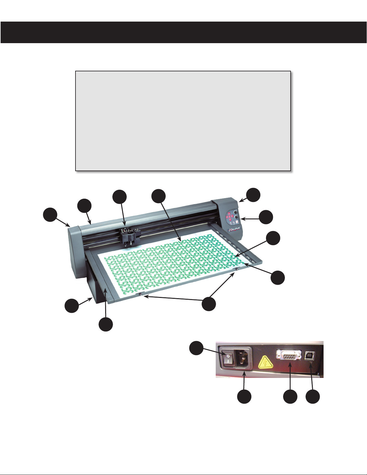
Visual Reference Guide
KEY
A
A. Left end cover
B. Dust cover
C. Carriage (design may
vary)
D. Adhesive sheet, mounted
E. Right end cover
F. Keypad
G. Tray (removable)
C
B
D
H. Origin (starting point)
I. Thumb nuts (2)
J. Table (non-removable)
K. Leg (2)
L. Power switch
M. Power connector
N. Serial port
O. USB port
E
F
G
H
K
I
J
L
M
2
Front view of the 300 System and a close-up photo of the port and power switch on the back of the machine.
N O
Page 3
Assembly
This Quick Start Guide shows how to assemble and set up the Ioline
300/350HF Systems. Consult the Acrobat® PDF 300/350HF System
User Guide, available online at ioline.com, for more detailed infor-
mation about installation and operation. Adobe® Acrobat® viewer is
required to read Ioline User Guides.
3
Unpacking the 300/350HF System
Follow the enclosed instruction sheet to remove the cutter and accessory kit from the box. To avoid injury, always lift the cutter with
two people. Check the packing list and save all packing materials.
1. Set the cutter on a stable surface.
2. If you purchased an extra tray, lift it off the Table and set it
aside.
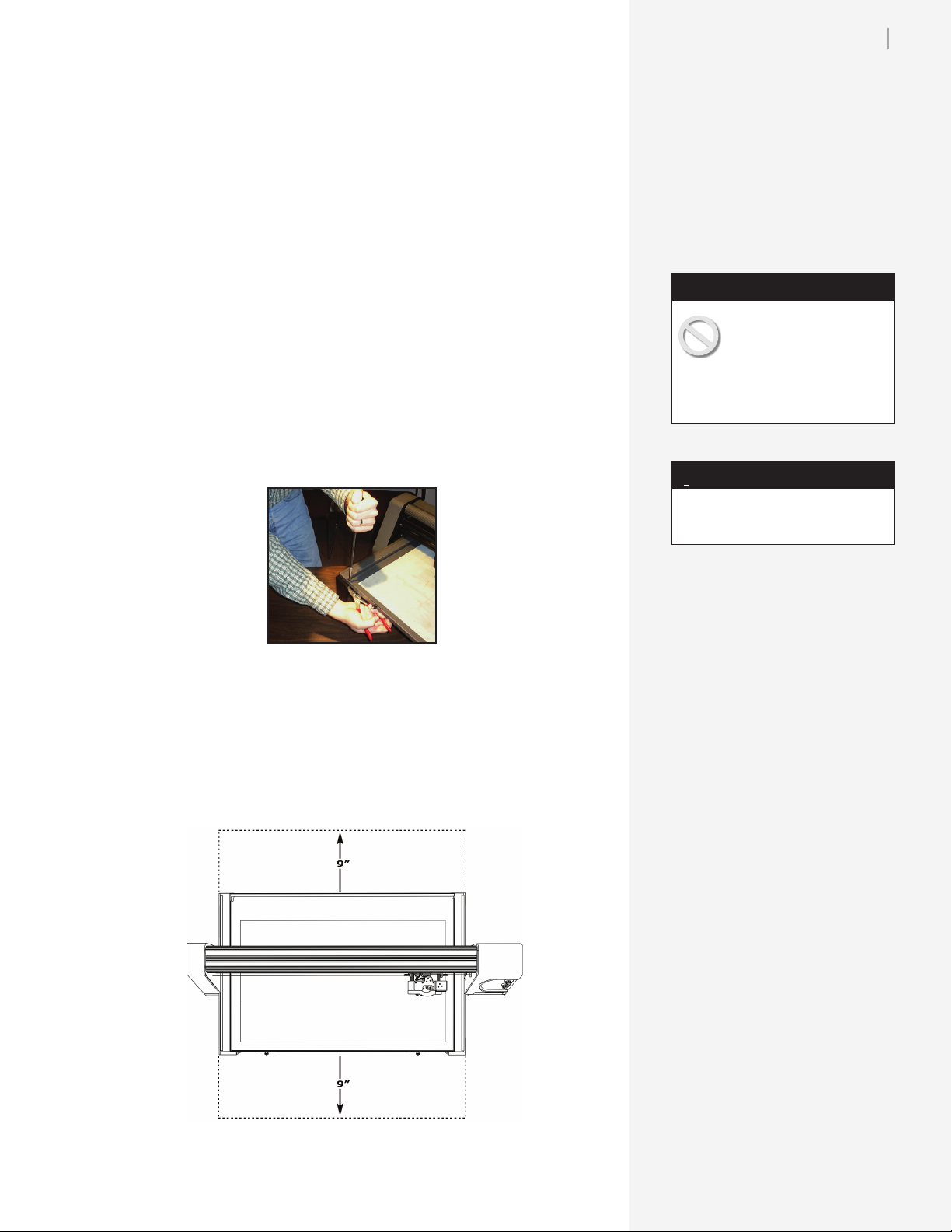
3. Remove the 4 shipping lock screws holding the Table in place
(see gure below).
Remove the shipping screws from the Table
4. Remove all the packing material from around the carriage.
Caution
The 300 and 350HF Systems are heavy and could
cause injury if they fall. A
minimum of two people are required to safely unpack and move
the cutter.
i
Save the box and all packing materials. New boxes are expensive!
Note
Prepare the Production Area
Clean the table top and clear any obstacles. Place the cutter 9-inches
away from the wall to allow the material tray to move freely forward and back. See the gure below.
Top view of the machine showing the area to keep clear for tray movement
Page 4

4
Ioline 300/350HF Quick Start Guide
Step 1: Install the Software
1. Make sure that machine power is turned off by pressing the ‘0’
end of the power switch on the back of the right end cover.
Power switch
set off to ‘0’
Make sure the power switch is OFF.
2. Visit the online Ioline software setup page at ioline.com/setup.
3. Click on the picture of the 300/350HF cutter then follow the
steps listed in the Setup tab.
4. Follow the self-guided installation instructions for each installation program. If prompted, answer ‘Yes’ or ‘OK’ to all questions about installing drivers.
i
Older 300 and 350HF Systems
used a parallel key rather than
USB, as shown below:
Note
5. The 301 installation program will place an icon on the desktop
for the 301 Software
The 301 software icon is placed on the desk-
top when installation is nished.
6. Restart the computer only if instructed.
7. Connect the Ioline 301 Software key to a USB port on the PC
(see gure below). Ioline recommends NOT using a USB hub
for the key. Windows will likely show messages about driver
installation when the key is inserted the rst time.
Install the drivers, then insert the USB key into the PC.
8. The PDF User Guide and this Quick Start Guide and software
manuals are available under the Manuals tab on the product
support page. Acrobat Reader, is required to view manuals.
9. The optional Ioline Control Center software is available on the
Downloads tab of the support page. This utility is normally
not required unless detailed machine setup is necessary or for
troubleshooting.
Page 5

Step 2: Connect the cutter to the PC
1. Insert the power cord into the power inlet on the cutter, then
plug it into a wall socket or power strip (see gure below).
5
Power cord
inlet
The power cord inlet, serial port and USB port on the rear panel of the cutter.
Cutter serial port
(9-pin female)
Cutter USB
port
2. Connect the USB cable supplied in the Accessory Kit to the cutter.
3. Verify that the cutter is positioned at least 9
inches away from the wall or other objects,
then turn the cutter power on. The Table
will move backward and the carriage to the
right. Wait for the keypad light to turn red,
indicating that the cutter has nished initializing.
4. Connect the USB cable to an empty USB
port on the computer.
5. Driver installation messages might appear
while the computer connects to the machine.
Rear view of the
PC USB ports.
Press OK and/or restart if requested.
Step 3: Install an adhesive sheet
1. Check the light on the cutter keypad and press Start/Stop if it is
not red. Use the Arrow keys on the keypad to move the Table
all the way forward.
2. If the tray is installed in the Table, loosen the thumb nuts and
remove the tray by lifting up in the front and pulling forward.
Place the tray on a stable surface.
3. Choose an Adhesive Sheet (and backing material, if required)
that are appropriate for the material you plan to cut. See Figure
Below to identify proper sheet and backing types. More information about choosing Adhesive Sheets is also available in the
300/350HF System User Guide.)
Page 6

6
Ioline 300/350HF Quick Start Guide
High Tack
(HT)
Medium Tack
(MT)
Low Tack
(LT)
Ultra Low Tack
(ULT)
2-sided Backing
(2S)
1-sided Backing
(1S)
Adhesive Sheet and backing material guidelines.
Scrim felt, leather, etching and stencil
board. Order 107076
A general purpose sheet, use with most
twills. Order 107295
Heatseal-backed or thin and fragile
materials. Order 107093
Paper or paper-backed materials. Order
108300
Adds adhesive to non-backed materials.
Order 107089
Stabilizes thin materials. Order 106227
i
Always remove the tray from the
cutter when removing or installing adhesive sheets. Not doing so
may damage the tray, table and/
or blade.
Note
Align the adhesive sheet with the L-shaped Tray alignment marks.
4. Peel the white backing paper off of the Adhesive sheet. The
STRIPED SIDE of the adhesive sheet should face up. With
the exposed side facing the Tray, align the corners of the sheet
with the engraved “L” shaped marks in the Tray (see gure at
right).
5. Smooth the adhesive sheet down until it is smooth. Leave the
paper cover on the top of the adhesive sheet until ready to apply material for cutting.
Page 7

Step 4: Install the material and tray
7
1. Remove the striped cover from the Adhesive Sheet and carefully apply fabric to the Tray. Smooth all bubbles out of the
material (see gure below). Remember to remove material and cover
the adhesive sheet with the striped paper sheet when the cutter is not
in use.
Apply the material on top of the Adhesive Sheet on the Tr a y.
i
DO NOT leave twill and other
materials stuck on the adhesive
sheet when not cutting. If left too
long, the adhesive on the sheet
will make a strong bond to the
material which makes removal
difcult. This might also ruin the
material and the adhesive sheet.
Note
2. Slide the Tray onto the Table with the thumb nuts facing the
front of the machine. Make sure the rear lip of the Tray ts
tightly under the rubber strip in the rear of the Table. The
thumb nut posts should drop smoothly into the slots on the
front of the Table.
3. Press the Tray down into the Table and tighten the thumb
nuts. Make sure the tray seats all the way into the table.
CORRECT
ü
INCORRECT
X
4. Use the Arrow keys on the keypad to position the carriage and
Table so that the blade over the Origin (usually the lower right
corner of the Table, see the Visual Reference Guide section). This
is where cutting will start.
5. Press Set Origin on the keypad. The light on the keypad will
turn green.
Page 8

8
Ioline 300/350HF Quick Start Guide
Caution
The blades are very sharp
and the tip is fragile. Use
caution when inserting
them into the blade holder.
i
You can substantially extend the
life of the blade by making sure
to adjust it to the proper depth
for the material you are cutting
and setting down-force pressure
as low as necessary to get a clean
cut, This also reduces the possibility Tr a y damage.
Note
Step 5: Select and adjust the blade
1. Choose one of the included blades in the Accessory Kit to
match the type of material loaded on the tray. The table below
shows information to help choose the correct blade.
Reduces fraying and pulling on fragile
30o Blade
0.094-in offset
45o Blade
0.094-in offset
60o Blade
0.094-in offset
2. Unscrew the foot (see
gure at right) from the
blade holder.
3. Insert the blade into the
blade holder (see gure
at right) by pinching the
shaft of the blade. DO
NOT touch the blade
tip, it is very sharp. The
blade will resist at first
then slide freely to a
hard stop when properly
inserted.
or exible materials.
300: Order 321 (PN 106988-5)
350HF: Order 324 (PN 107418-5)
General purpose blade. Cuts some
thick materials.
300: Order 322 (PN 106989-5)
350HF: Order 325 (PN 107419-5)
For cutting thick and stiff materials.
350HF: Order 326 (PN 107420-5)
Blade selection guidelines.
Blade
Blade
Holder
Foot
i
The are great accessories for the
300 and 350HF that make your
business even more productive.
Extra Blade Holder (107080)
Allows quick change between two
cutting depths when switching
materials.
Extra Removable Tray (107662)
Increase throughput by weeding
one tray while cutting on another.
Precision Weeding Tool (106143)
Swiss made superior quality tweezers with sharp tips for fast and
precise weeding.
i
Check our website, give us a call,
or send an email...
Accessories
NEED HELP?
4. Gently turn the foot onto
Installing the blade in the blade holder.
the blade holder until just
before the tip of the blade
protrudes from the opening in the foot.
5. Insert the blade holder in the
jaw then tighten the clamp.
6. Follow the steps in the
300/350HF System User Guide
to adjust the blade exposure
and force. Note: this step is
very important!
7. Proceed to the 301 User Guide
to learn about preparing files
and sending them to the cutter.
The machine is ready to
Material
Adhesive Sheet
A properly adjusted blade.
Blade
Foot
cut a le!
Ioline Corporation Woodinville, Washington U.S.A.
M-F, 7:00 A.M. - 5:00 P.M. U.S. Pacic Time
Voice: 1.425.398.8282 Fax: 1.425.398.8383
support@ioline.com www.ioline.com
 Loading...