

Page 1
300 System
CORPORACORPORA
CORPORA
CORPORACORPORA
TIONTION
TION
TIONTION
Contents
• Unpack the Cutter
• Cutter Connections
• Computer Connections
• Install Ioline Software
• Install an Adhesive Sheet
• Apply Cloth and Install the Tray
• Choose a Blade
C
Quick Start Guide
This quick start guide has instructions for
setting up and using the Ioline 300 System. Please consult the 300 System User
Guide and the 301 Software User Guide
for more information about getting the
most out of your Ioline product.
E
D
B
A
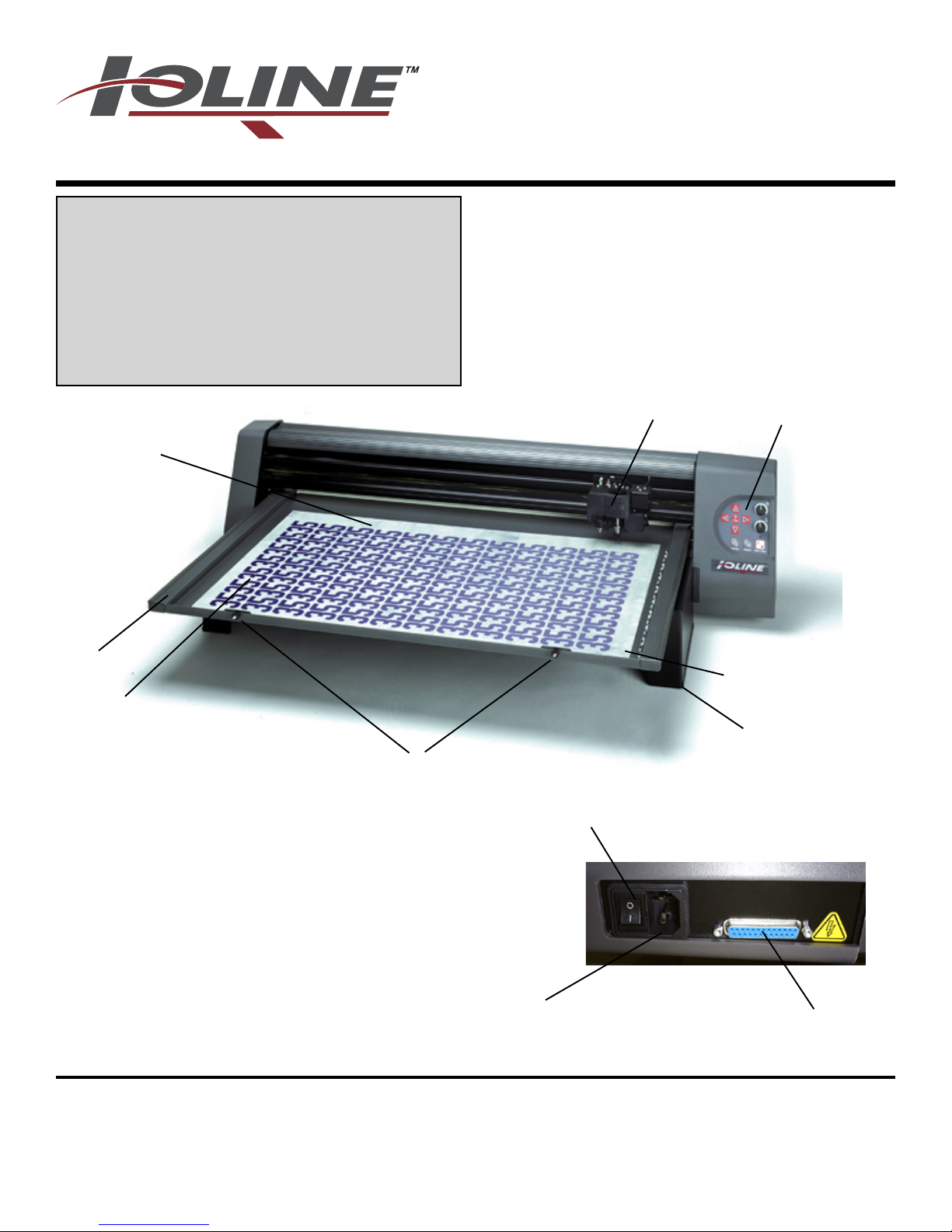
A. Tray (removable)
B. Table (non-removable)
C. Adhesive Sheet, Mounted
D. Keypad
E. Carriage
F. Serial Port
G. Power Connector
H. Power Switch
J. Most Cuts Start Here (Origin)
K. Thumb Nuts (2)
L. Leg (2)
14140 N.E. 200th Street, Woodinville, WA 98072, USA
Part Number: PRINT:107077r5 • FILE:107070r3
J
L
K
H
G
F
IOLINE CORPORATION
Voice: 1.425.398.8282 • Fax: 1.425.398.8383
info@ioline.com • www.ioline.com
Page 2
2 300 Quick Start Guide
Unpack the Cutter
1. Remove the machine and all accessories from the box using the
included instruction sheet.
2. Set the 300 on a stable surface.
Lift the Tray from the Table.
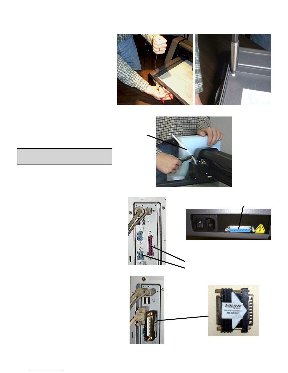
3. Remove the 4 screws holding the
Table in place for shipping. Fig. A.
4. Cut the tie wrap that holds the
Carriage in place and remove all
packing material. Fig. B
5. Make sure the cutter has a minimum of 9” clearance in front and
behind the Legs of the plotter.
IMPORTANT: Save the shipping
box and all of the contents.
Cutter Connections
1. Insert the power cord into the 300
then plug it into a wall socket or
power strip. Fig. C.
2. Connect the supplied serial cable
to the cutter. Fig. C.
3. Turn the cutter power on. The
Table will move to the back and
the Carriage to the right. The
Keypad light will turn red when the
cutter is finished initializing.
Figure A: Removing the shipping screws (4) from the Table.
Tie Wrap
Figure B: Cut the shipping tie wrap holding the Carriage.
Plotter Serial Port: 25 Holes (Female)
Figure C: The rear panel on the 300. Power
Switch, Power Connector, and Serial Port.
Computer Connections
1. Power off the computer. Connect the Ioline 301 Software Key
to the Parallel Port (25 holes).
Figs. D, E & F.
2. Connect the serial cable to the
port on the computer. Use a 925 pin adapter if required. Fig. E.
3. The cable configuration between
the cutter and computer should
resemble the photo in Figure E.
4. Turn the computer power on.
Figure D: Back of computer:
Parallel Port and Serial Port.
Figure E: Cable configuration for the
300 and 301 on the computer.
Computer Parallel Port: 25 Holes (Female)
Computer Serial Port: 9 or 25 Pins (Male)
Figure F: Ioline 301 Software
Key (installed in the Parallel Port
on the computer).
Page 3

300 Quick Start Guide 3
Install Ioline Software
1. Insert the 300 Software CD-ROM into the
CD-ROM drive.
2. The installation should start automatically.
If it does not, go to Start Menu>Run.
Click on Browse and choose the CD-ROM
drive (usually D:\). Select iosetup.exe then
Open and Run.
3. Follow the self-guided installation instructions to install the Ioline Control Center,
301 Software, Acrobat Reader, and all
manuals. Fig G.
4. A window may appear asking to install
Hardlock drivers. Answer ‘Yes’ to all questions.
5. Restart the computer if requested. All icons
chosen in the installation will appear on
the desktop. Fig. H.
Install an Adhesive Sheet
1. Ensure that the light on the 300 Keypad is
red. Press Start/Stop if it is not. Use the
Arrow keys on the Keypad to move the
Table all the way forward.
2. If the Tray is installed in the Table, loosen
the Thumb Nuts and remove it by lifting
up in the front and pulling forward. Place
the tray on a stable surface.
3. Choose an adhesive sheet and backing
material (if required) that will work with
the material planned for cutting. Table 1
is a guide for choosing the proper sheet
and backing types. There is more information about choosing adhesive sheets
in the 300 System User Guide.
Figure G: The 300 software installation screen.
Figure H: Ioline Software Icons.
kcaThgiH
)TH(
kcaTmuideM
)TM(
kcaTwoL
)TL(
dediS2
)S2(gnikcaB
dediS1
)S1(gnikcaB
Table 1: Adhesive sheet and backing material application table.
.slliwttsomhtiw
,rehtaelniht,tlefmircS
.draoblicnetsdnagnihcte
dnanihtrodekcablaestaeH
.slairetameligarf
.slairetamdekcabevisehda
.slairetamnihtezilibatS
esu,teehsesopruplarenegA
-nonotecafrusevisehdasddA
4. Peel the backing paper off of one side.
With the exposed side facing the Tray,
align the corners of the sheet with the “L”
shaped marks in the tray. Fig. J.
5. Smooth the adhesive sheet down until all
bubbles are removed. Leave the paper
cover on the top of the adhesive sheet
until ready to apply material for cutting.
Figure J: Align the adhesive sheet with the System 300 alignment marks.
Page 4

4 300 Quick Start Guide
Apply Cloth & Install the Tray
1. Remove the cover from the Adhesive Sheet
and carefully apply fabric to the Tray. Smooth
all bubbles out of the material. Fig. K.
2. Slide the Tray onto the Table with the Thumb
Nuts facing the front of the machine. Make
sure the rear lip of the Tray fits tightly under
the white strip in the rear of the Table. The
thumb nut posts should drop smoothly into
the slots on the front of the Table.
3. Press the Tray down into the Table and
tighten the Thumb Nuts.
4. Use the Arrow keys on the Keypad to position the Carriage and Table so that the knife
is in lower right corner of the Table. This is
where cutting will start.
5. Press Set Origin on the Keypad. The light
on the Keypad will turn green.
Figure K: Applying material to the Tray.
edalB123
889601NP
tesffo"490.0-°03
nogniyarfsecudeR
dnaslairetameligarf
elbixelfnognillup
.slairetam
Choose a Blade
1. Find the included 322 blade in the accessory
kit. Table 2 shows blade usage information.
2. Unscrew the Foot (Figure N) from the Blade
Holder.
IMPORTANT: The Blades are very sharp and
the tip is fragile. Use caution when inserting
them into the Blade Holder.
3. Insert the Blade into the Blade Holder (Figure N). It will resist at first then slide freely
to a hard stop when properly inserted.
4. Gently turn the Foot onto the Blade Holder
until just before the tip of the blade protrudes
from the opening in the foot.
5. Follow the steps in the 300 System User
Guide to adjust blade exposure and force.
This step is very important!
Blade
Blade
Holder
edalB223
989601NP
tesffo"490.0-°54
.edalbesopruplareneG
.slairetamkcihtstuC
Table 2: Blade application table.
Foot
6. The 300 is ready to cut!
TIP: Properly adjusted blade depth and force
will substantially increase the life of the
blade, adhesive sheet and reduce the
chance of damaging the tray.
Figure N: Blade installation into
the Blade Holder.
A
M
d
a
h
t
e
e
s
i
v
e
s
h
e
e
t
Figure P: A Properly adjusted
Blade.
F
B
o
l
a
o
d
t
e
r
i
a
l
t
o
c
u
t
 Loading...