

TM
Flare
High-Speed CMOS Area Scan Camera Series
2M280 / 4M140
CoaXPress
Copyright © 2011 IO Industries Inc. All rights reserved.
Flare is a pending trademark of IO Industries Inc.
User's Manual
Revision 2.0

2
Flare CXP User's Manual
Notice
The material contained in this manual consists of information that is proprietary to IO
Industries Inc. and may only be used by the purchasers of the product and IO Industries Inc.
authorized distributors or resellers. IO Industries Inc. makes no warranty for the use of its
product and assumes no responsibility for any errors that may appear or for damages
resulting from the use of the information contained in this manual. IO Industries Inc. reserves
the right to make changes to this manual at any time without notice.
Warranty
The Flare CL product family is warranted for one (1) year from the date of purchase unless
otherwise agreed in writing. If the product proves to be defective during this warranty period,
IO Industries Inc. will, at its discretion, either repair or replace the product at no cost. In the
case where a new device is to be provided but the product has been discontinued, a product
with similar or better performance capabilities and features will be provided. This warranty
shall not apply to any damage, defect or failure caused by improper use or inadequate
maintenance of the product.
Certifications
FCC Class A Digital Device or Peripheral – Information to User
NOTE
This equipment has been tested and found to comply with the limits for a Class A digital
device, pursuant to Part 15 of the FCC Rules. These limits are designed to provide
reasonable protection against harmful interference when the equipment is operated in a
commercial environment. This equipment generates, uses, and can radiate radio frequency
energy and, if not installed and used in accordance with the instruction manual, may cause
harmful interference to radio communications. Operation of this equipment in a residential
area is likely to cause harmful interference in which case the user will be required to correct
the interference at his own expense.
WARNING
Changes or modifications not expressly approved by IO Industries Inc. could void the user's
authority to operate the equipment.
CE Compliance
This equipment has been certified to conform to the requirements of Council Directive
89/336/EC for electromagnetic compatibility and to comply with the following European
Standards:
• Immunity: EN55024:1998, A1:2001
• Emissions: EN55022:1998 Class A / CISPR 22:1997
All IO Industries Inc. products bearing the CE mark have been declared to be in conformance
with the applicable EEC Council Directives. Note that the use of interconnect cables that are
IO Industries Inc. www.ioindustries.com Revision 2.0

3
not properly grounded and shielded may affect CE compliance.
Flare CXP User's Manual
About IO Industries Inc.
Established in 1991, IO Industries Inc. designs high performance digital imaging products for
applications in manufacturing, research, vehicle-mounted systems, and video game content
creation. Products include PC-based, standalone and peripheral DVR systems; and high
speed CMOS area scan digital cameras.
Contact Information
IO Industries Inc.
12-1510 Woodcock St.
London, Ontario
N6H 5S1 CANADA
Tel: (519) 663-9570
Fax: (519) 663-9571
Sales: sales@ioindustries.com
Technical Support: support@ioindustries.com
IO Industries Inc. www.ioindustries.com Revision 2.0

4
Flare CXP User's Manual
Table of Contents
1 Introduction..............................................................................................................................6
1.1 Camera Highlights...........................................................................................................6
1.2 Sensor Specifications......................................................................................................7
1.3 Cover Glass Transmittance.............................................................................................8
1.4 Monochrome and NIR Spectral Response.....................................................................9
1.5 Color Spectral Response...............................................................................................10
1.6 Bayer Pattern.................................................................................................................10
2 Mechanical............................................................................................................................11
2.1 Mechanical Specifications.............................................................................................12
2.2 Lens Adapter..................................................................................................................12
2.3 Power.............................................................................................................................13
2.4 External Triggers............................................................................................................14
2.5 LED Status Indicator......................................................................................................16
3 Camera Control.....................................................................................................................17
3.1 Register Map..................................................................................................................17
3.2 CoaXPress Output Format............................................................................................24
3.3 Image Windowing..........................................................................................................24
3.4 Image Sub-Sample........................................................................................................26
3.5 Exposure Mode..............................................................................................................27
3.5.1 Free-run programmable exposure.........................................................................27
3.6 Edge-triggered programmable exposure.......................................................................28
3.7 Edge-triggered level-controlled exposure......................................................................29
3.8 Edge-triggered double exposure...................................................................................30
3.9 Frame Period and Exposure .........................................................................................31
3.10 High Dynamic Range Modes.......................................................................................36
3.10.1 Interleaved HDR Exposure Mode........................................................................36
3.10.2 Piecewise HDR Exposure Mode..........................................................................37
3.11 Offset and Gain.............................................................................................................39
3.11.1 Digital Offset........................................................................................................39
3.11.2 Analog Gain.........................................................................................................39
3.11.3 ADC Gain and Ramp Voltage..............................................................................39
3.11.4 Digital Gain..........................................................................................................40
3.12 Image Flipping.............................................................................................................40
3.13 Test Pattern..................................................................................................................41
3.14 Sensor Artifacts............................................................................................................45
3.14.1 Horizontal Line......................................................................................................45
3.14.2 Black Sun.............................................................................................................46
3.15 Bad Pixel Replacement...............................................................................................46
3.16 Command Memory......................................................................................................47
3.17 Camera Reset..............................................................................................................47
3.18 Control Packet CRC....................................................................................................47
IO Industries Inc. www.ioindustries.com Revision 2.0

5
3.19 Device Discovery.........................................................................................................47
4 Optional RS-485 Control.......................................................................................................48
4.1 RS-485 Command Summary........................................................................................48
5 Accessories...........................................................................................................................54
6 Document Revision History...................................................................................................54
7 Firmware Revision History....................................................................................................55
Flare CXP User's Manual
IO Industries Inc. www.ioindustries.com Revision 2.0

6
Flare CXP User's Manual
1 Introduction
The Flare CoaXPress (CXP) series is a family of high-speed CMOS area scan cameras
designed for a broad range of applications. Table 1 shows the camera models covered in this
manual.
Model Resolution Color Output Format
2M280MCX
2M280CCX Bayer
2048 x 1088
2M280CCX-NF Bayer, no IR cut filter
2M280NCX Near Infrared
4M140MCX
4M140CCX Bayer
2048 x 2048
4M140CCX-NF Bayer, no IR cut filter
4M140NCX Near Infrared
Table 1. Covered Flare CXP models
Monochrome
Monochrome
1.1 Camera Highlights
➢ CXP-3 single and dual link output configurations
➢ 2MP max. 280 fps (8-bit), 224 fps (10-bit) - 2M280
➢ 4MP max. 140 fps (8-bit), 112 fps (10-bit) - 4M140
➢ Pipelined global shutter with Correlated Double Sampling (CDS)
➢ High sensitivity with low noise
➢ Multiple High Dynamic Range (HDR) modes
➢ 10-bit ADC resolution (selectable 8/10-bit output)
➢ Programmable and triggered exposure control
➢ Multiple windows with up to 8 separate Regions Of Interest (ROI)
➢ Image Sub-sampling
➢ Rugged aluminum case
➢ C-mount lens adapter, or optionally use T- or CS-mount
➢ Minimum exposure times of 16 µs
➢ Analog (up to 1.6x) and digital (up to 16x) gains
➢ Low power (4.5W @ 24V), Power Over CoaXPress (PoCXP)
CoaXPress
CXP-3
Single and Dual Link
IO Industries Inc. www.ioindustries.com Revision 2.0

7
1.2 Sensor Specifications
Specification 2M280 4M140
Effective Pixels 2048 x 1088 2048 x 2048
Optical Format 2/3" 1"
Pixel Pitch 5.5 x 5.5 µm
Full Well Charge 13.5 Ke-
Conversion Gain 0.075 LSB/e-
Sensitivity 5.56 V/lux.s
Temporal Noise 13 e-
Dynamic Range 60 dB
Parasitic Light Sensitivity < 1/50000
Fill Factor < 50% (with micro lenses)
Flare CXP User's Manual
2
Quantum Efficiency < 50% @ 550nm (with micro lenses)
Dark Current Signal 125 e-/s (at 25ºC)
DSNU 3 LSB/s (10-bit)
Fixed Pattern Noise < 1 LSB RMS (10-bit)
PRNU < 1% of signal
Cover Glass Plain D263
Bad Columns ( > 100 pixels) 0
Bad Rows ( > 100 pixels) 0
Bad Pixels
Dark Image: > 6 x FPN Value
Bright Image: < 80% Swing
Cluster Defects ( > 1 pixel) 0
max. 100 max. 200
Table 2. Sensor specifications
IO Industries Inc. www.ioindustries.com Revision 2.0
8
Flare CXP User's Manual
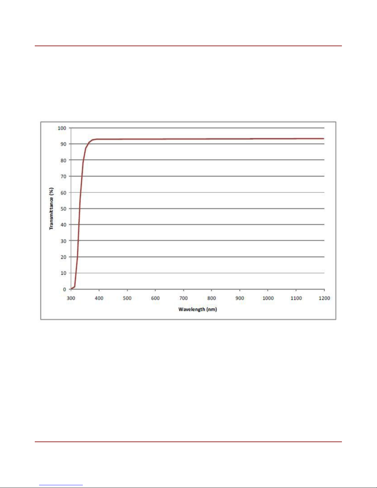
1.3 Cover Glass Transmittance
Plain D263 cover glass is used on all models. The glass transmittance is shown below. The
glass refraction index is 1.52.
Figure 1. Cover Glass Transmittance
IO Industries Inc. www.ioindustries.com Revision 2.0
9
Flare CXP User's Manual
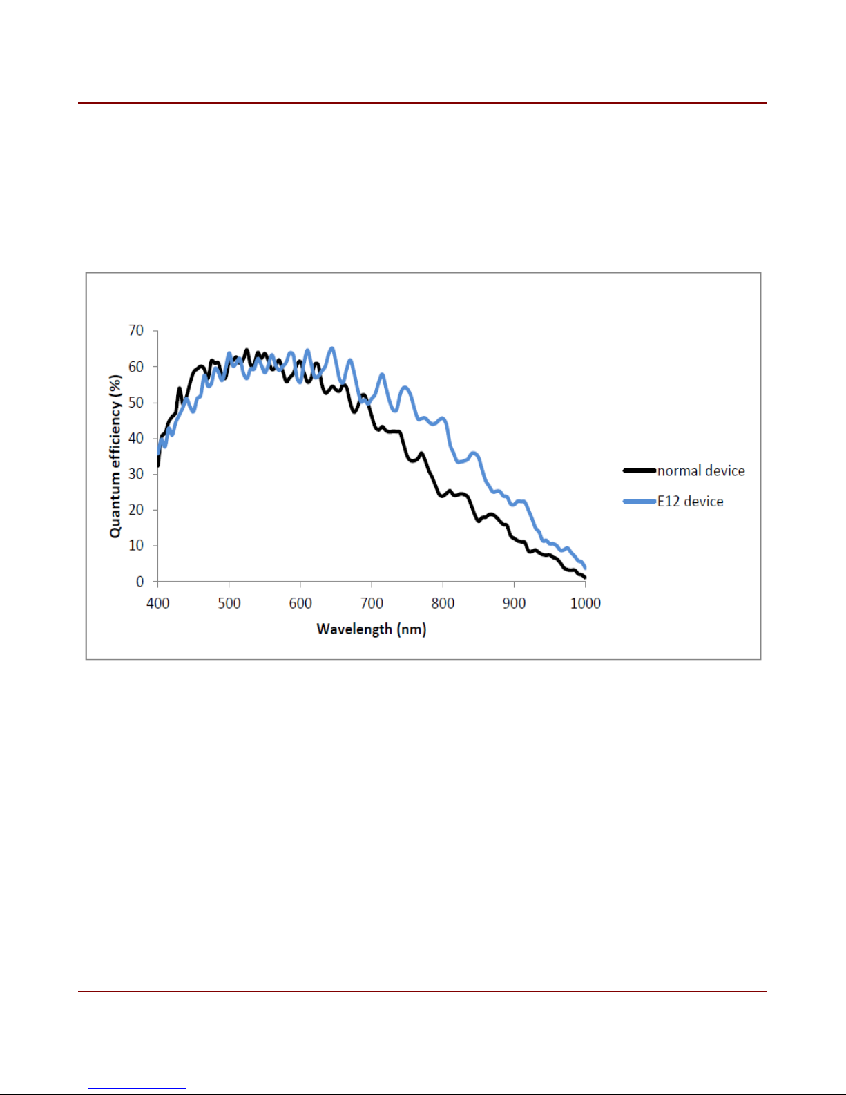
1.4 Monochrome and NIR Spectral Response
A typical spectral response of monochrome 2M280 and 4M140 cameras (normal device) and
near infrared cameras (E12 device), with D263 cover glass, are shown below.
Figure 2. Monochrome and NIR spectral response
IO Industries Inc. www.ioindustries.com Revision 2.0
10
Flare CXP User's Manual
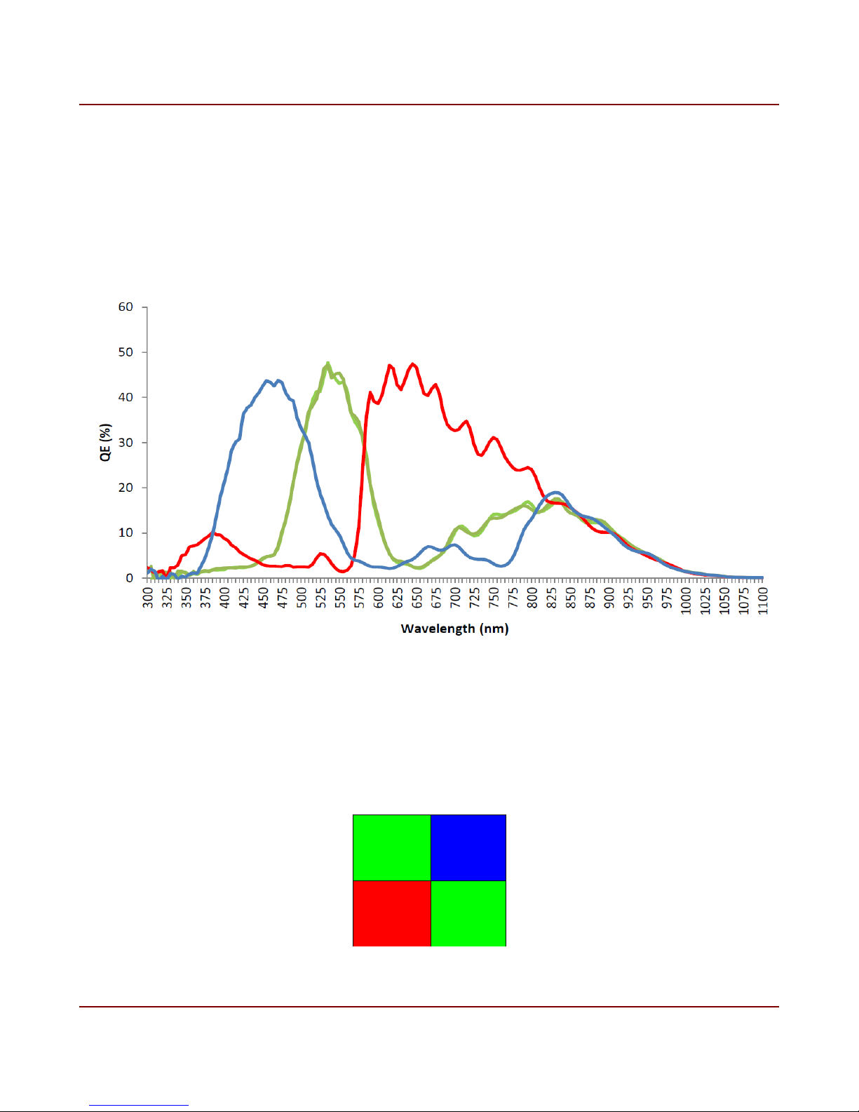
1.5 Color Spectral Response
A typical spectral response of the color 2M280 and 4M140 cameras, with D263 cover glass
and color filters is shown below. Flare color CXP models come standard with an IR cut filter
in the optical path to obtain good color separation. The cutoff wavelength of the filter is
645nm.
Figure 3. Color spectral response
1.6 Bayer Pattern
The 2M280 and 4M140 are both available in color. The Bayer pattern is shown in figure 4.
G
Pixel
(1,1)
R
Pixel
(1,2)
Figure 4. Bayer color filter array pattern
IO Industries Inc. www.ioindustries.com Revision 2.0
B
Pixel
(2,1)
G
Pixel
(2,2)
11
Flare CXP User's Manual
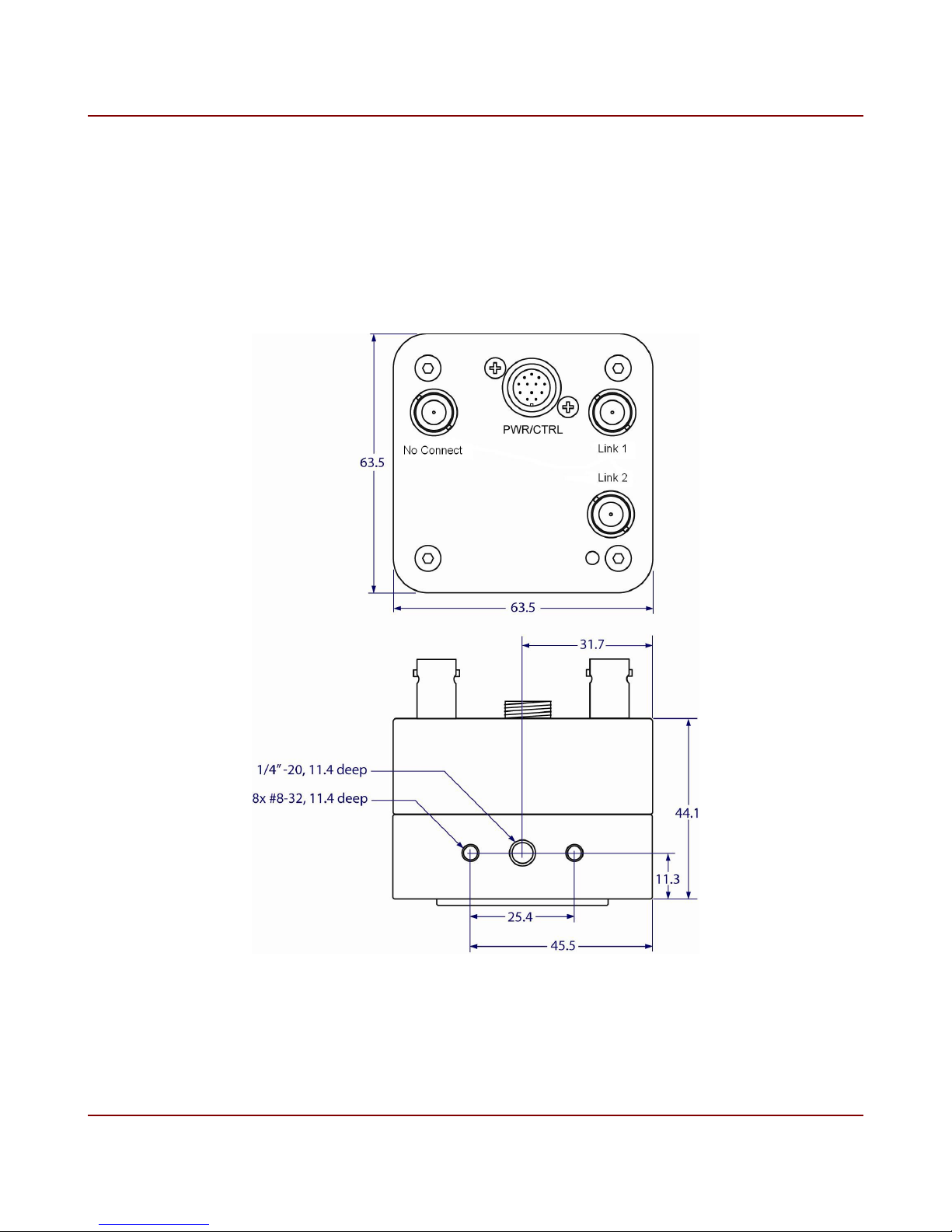
2 Mechanical
Camera housings are made with high precision from machined aluminum. Mechanical
drawings are shown in figure 5.
Figure 5. Mechanical drawings
IO Industries Inc. www.ioindustries.com Revision 2.0
12
Flare CXP User's Manual
2.1 Mechanical Specifications
Summary of mechanical specifications are shown in table 3. Mounting holes on all sides of
the camera provides many mounting options.
Specification Description
Size 63.5 mm x 63.5 mm x 44.1 mm
Weight 318 g
Mounting Holes Bottom - 1x 1/4"-20 (tripod)
All sides - 2 x #8-32, separation 1"
Power Connector 12-pin threaded Hirose
Mating connector part # HR10A-10TPA-12S(73)
Video Output 2 x standard BNC
Table 3. Mechanical specifications
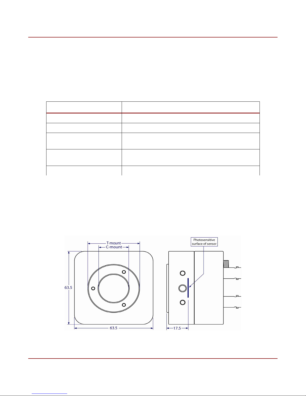
2.2 Lens Adapter
Aluminum C-mount lens adapter precisely calibrated to standardize focal length to sensor,
see figure 6.
Figure 6. Lens adapter
IO Industries Inc. www.ioindustries.com Revision 2.0

13
The position of the lens adapter is set using specialized equipment to ensure the proper back
focus of each camera. Three set screws (M2.5 - 1.3mm hex) on the front of the adapter are
used to firmly hold the ring adapter in place. In most cases it is not recommended to change
the position of the adapter ring. In rare cases the back focus can be adjusted to improve
image sharpness when using lower cost zoom lenses or custom optics.
The size of adapter ring is T-mount, with standard threading. It is possible to use a T-mount
extension tube with T-mount lenses; commonly Telephoto Zoom and Telescope lenses.
Between the adapter ring and the sensor there is another section of C-mount threading. With
a spacer ring (Edmund Optics spacer ring kit G54-461) this section can be used for a CSmount lens. This section can also be used to insert a filter in the optical path of the camera.
Flare CXP User's Manual
2.3 Power
Flare CXP cameras are powered using a 12-24 V ± 10% DC power source. The power
connector is shown in figure 7, and the pinout is shown in table 4.
The camera can optionally be powered over the coax cable (PoCXP) from a compliant frame
grabber on the Link 1 connector only. It is recommended to remove the power adapter from
the camera power connector when using the camera in a PoCXP configuration.
Pin Description Pin Description
1 Trigger Input 1 7 Trigger Return
2 RS485+ 8 Trigger VCC
3 12-24 V 9 RS485-
4 12-24 V 10 Trigger Out 1
5 GND 11 NC
6 GND 12 NC
Table 4. Power connector pinout Figure 7. Power connector
IO Industries Inc. www.ioindustries.com Revision 2.0
14
Flare CXP User's Manual
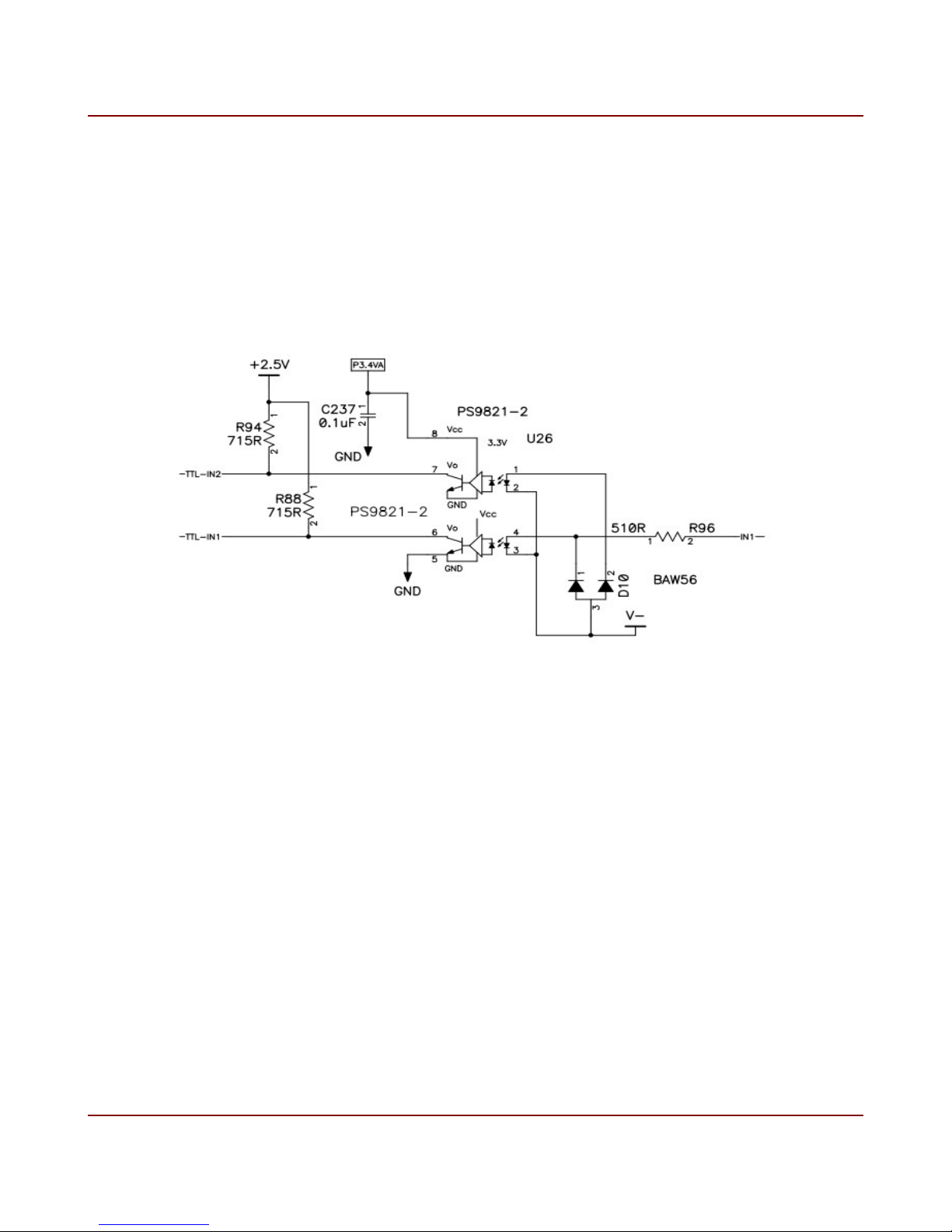
2.4 External Triggers
There is one opto-isolated input on the power connector, pin 1. Only ground must be
provided as a reference for the input. The voltage range on the input is 4.5 to 7.5 V, and the
input delay is approximately 100 ns. The input current range is 6 to 12 mA. The circuit
diagram for the opto-isolated input is shown in figure 8.
Figure 8. Opto-isolated input circuit diagram
The opto-isolated input circuit uses a high-speed photocoupler from Renesas Technology
Corporation, part # PS9821-2. Note TTL-IN2 is not used.
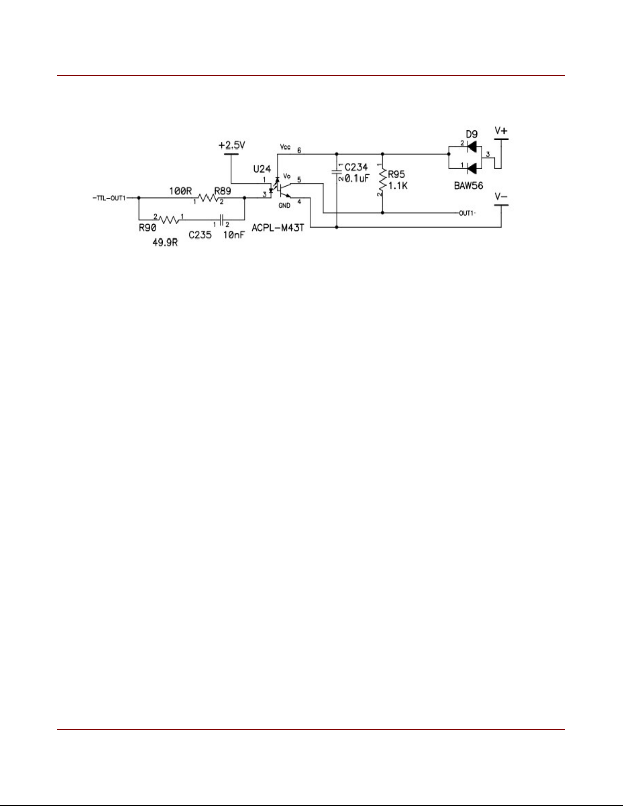
There is one opto-isolated output on the power connector (pins 10 and 9). Power (4.5 to 15
V) and ground must be provided for this output. The maximum output delay is approximately
1 µs. An external pull-up resistor is not required, but if one is used it must be greater than 2
kΩ. The circuit diagram for the opto-isolated output is shown in figure 9.
IO Industries Inc. www.ioindustries.com Revision 2.0
15
Flare CXP User's Manual
Figure 9. Opto-isolated output circuit diagram
The opto-isolated output circuit uses a single channel high speed digital optocoupler (Avago
Technologies part # ACPL-M34T).
IO Industries Inc. www.ioindustries.com Revision 2.0

16
Flare CXP User's Manual
2.5 LED Status Indicator
A tri-color (orange/green/red) LED on the back of the camera is used to indicate operational
status. Table 5 summarizes the operating states indicated by the LED.
LED State Description
Solid Orange Camera is initializing.
Fast flash alternate
Green/Orange
(20ms on, 60ms off)
Solid Green Connected, no data being transferred.
Fast flash Green
(20ms on, 60ms off)
Fast flash Red
(20ms on, 60ms off)
Table 5. LED status
Connection in progress, waiting for StreamPacketSizeMax
bootstrap register to be written with a non zero value.
Will be shown for a minimum of 1 second.
Data being transferred.
Camera error. Issue with internal flash memory or image
sensor.
IO Industries Inc. www.ioindustries.com Revision 2.0

17
3 Camera Control
3.1 Register Map
The register map for the Flare CXP cameras is shown in table 6.
Flare CXP User's Manual
Address Name / Description Group Access Length
Description
(bytes)
Bootstrap Registers
0x00000000 Standard Support R 4 Returns 0xC0A79AE5
0x00000004 Revision Support R 4 0x00010000
0x00000008 XmlManifestSize Support R 4 0x00000001
0x0000000C XmlManifestSelector Support R/W 4 0x00000000
Currently only 1 manifest in
camera's non-volatile
memory
0x00000010 XmlVersion Support R 4 0x00010000
0x00000014 XmlSchemaVersion Support R 4 0x00010100
0x00000018 XmlUrlAddress Support R 4 0x00006000
0x0000001C Iidc2Address Support R 4 0x00000000
Not used
0x00002000 DeviceVendorName Genicam R 32 Returns string:
IO Industries Inc
0x00002020 DeviceModelName Genicam R 32 Flare xMxx0 xCX
0x00002040 DeviceManufacturerInfo Genicam R 48 NULL
0x00002070 DeviceVersion Genicam R 32 NULL
0x00002090 DeviceFirmwareVersion Genicam R 32 Returns firmware version
0x000020B0 DeviceID Genicam R 16 Returns device serial
0x000020C0 DeviceUserID Genicam R/W 16 NULL from factory, saved
0x00003000 WidthAddress CXP R 4 Returns 0x40000004
0x00003004 HeightAddress CXP R 4 0x40000008
0x00003008 AcquisitionModeAddress CXP R 4 0x00000000
0x0000300C AcquisitionStartAddress CXP R 4 0x10000020
IO Industries Inc. www.ioindustries.com Revision 2.0
number
to non-volatile memory
when written

18
Flare CXP User's Manual
Address Name / Description Group Access Length
Description
(bytes)
0x00003010 AcquisitionStopAddress CXP R 4 0x10000024
0x00003014 PixelFormatAddress CXP R 4 0x40000000
0x00003018 DeviceTapGeometryAddress CXP R 4 0x20000000
0x0000301C Image1StreamIDAddress CXP R 4 0x00007000
0x00003020 Image2StreamIDAddress CXP R 4 0x00007004
0x00004000 ConnectionReset CXP W 4 Write 0x00000001 to reset
connection
0x00004004 DeviceConnectionID CXP R 4 Returns 0x00000000 on
Master Link, and
0x00000001 on Extension
Link
0x00004008 MasterHostConnectionID CXP R/W 4 Returns 0x00000000 after
connection reset, or last
writen value on Master Link
since power up
0x0000400C ControlPacketSizeMax CXP R 4 Max control packet size is
1024 bytes. Returns
0x00000400
0x00004010 StreamPacketSizeMax CXP R/W 4 Write any value, max
packet size used is 2044
bytes
0x00004014 ConnectionConfig CXP R/W 4 Only 3.125Gbps supported
and up to two links. Write
this register to change the
number of links:
1 link – 0x00010038
2 links 0x00020038
0x00004018 ConnectionConfigDefault CXP R 4 Reflects ConnectionConfig
register
0x0000401C TestMode CXP R/W 4 Not implemented (v04
firmware)
0x00004020 TestErrorCountSelector CXP R/W 4 -
0x00004024 TestErrorCount CXP R/W 4 -
0x00004028 TestPacketCountTx CXP R/W 8 -
0x00004030 TestPacketCountRX CXP R/W 8 -
0x00004038 ElectricalComplianceTest CXP R/W 4 -
0x0000403C HsUpconnection CXP R 4 No high-speed uplink
IO Industries Inc. www.ioindustries.com Revision 2.0

19
Flare CXP User's Manual
Address Name / Description Group Access Length
Description
(bytes)
Command/Status Registers
0x00006000 XML URL String - R - Read to first NULL
character. Example URL:
“Local:IOIndustries_Flare_
2M280CCX_v04.xml;60000
000;95584”
0x00007000 Stream ID #1 R 4 Returns 0x00000001
0x00007004 Stream ID #2 R 4 0x00000000
0x10000020 Acquisition Start W 4 Write 0x00000001 to start
imaging
0x10000024 Acquisition Stop W 4 Write a 0x00000001 to stop
imaging
0x20000000 Tap Geometry R 4 Returns 0x00000000
0x20000004 Width (Current HR) R 4 Returns current horizontal
resolution of the output
image
0x20000008 Height (Current VR) R 4 Returns current vertical
resolution of the outpout
image
0x2000000C Window Update Status R 4 After the Set Window
register is written, if all
settings are valid this
register will return 0. A
value of 1-8 indicates
which window settings are
invalid
0x30001008 Min HR R 4 Minimum horizontal
resolution (16 pixels)
0x30001010 Min VR R 4 Minimum vertical resolution
(4 lines)
0x30001078 Min Frame Period R 4 Minimum frame period, in
µs
0x3000107C Min Exposure 1 R 4 Minimum exposure time 1,
in µs
0x30001080 Min Exposure 2 R 4 Minimum exposure time 2,
in µs
0x30001084 Min Exposure 3 R 4 Minimum exposure time 3,
in µs
0x30002008 Max HR R 4 Maximum horizontal
resolution
IO Industries Inc. www.ioindustries.com Revision 2.0

20
Flare CXP User's Manual
Address Name / Description Group Access Length
Description
(bytes)
0x30002010 Max VR R 4 Maximum vertical
resolution
0x30002078 Max Frame Period R 4 Maximum fame period, in
µs
0x3000207C Max Exposure 1 R 4 Maximum exposure time 1,
in µs
0x30002080 Max Exposure 2 R 4 Maximum exposure time 2,
in µs
0x30002084 Max Exposure 3 R 4 Maximum exposure time 3,
in µs
0x40000000 Pixel Format R/W 4 0 – 8bit
1 – 10bit
0x40000004 Number of Windows R/W 4 Range 1 to 8
0x40000008 Output Horizontal Resolution R/W 4 Horizontal resolution of all
windows
0x4000000C ROI-1 HR Start R/W 4
0x40000010 ROI-1 Vertical Resolution R/W 4
0x40000014 ROI-1 VR Start R/W 4
0x40000018 ROI-2 HR Start R/W 4
0x4000001C ROI-2 VR R/W 4
0x40000020 ROI-2 VR Start R/W 4
0x40000024 ROI-3 HR Start R/W 4
0x40000028 ROI-3 VR R/W 4
0x4000002C ROI-3 VR Start R/W 4
0x40000030 ROI-4 HR Start R/W 4
0x40000034 ROI-4 VR R/W 4
0x40000038 ROI-4 VR Start R/W 4
0x4000003C ROI-5 HR Start R/W 4
0x40000040 ROI-5 VR R/W 4
0x40000044 ROI-5 VR Start R/W 4
0x40000048 ROI-6 HR Start R/W 4
0x4000004C ROI-6 VR R/W 4
0x40000050 ROI-6 VR Start R/W 4
0x40000054 ROI-7 HR Start R/W 4
0x40000058 ROI-7 VR R/W 4
IO Industries Inc. www.ioindustries.com Revision 2.0

21
Flare CXP User's Manual
Address Name / Description Group Access Length
Description
(bytes)
0x4000005C ROI-7 VR Start R/W 4
0x40000060 ROI-8 HR Start R/W 4
0x40000064 ROI-8 VR R/W 4
0x40000068 ROI-8 VR Start R/W 4
0x4000006C Sub-Sample R/W 4
0x40000070 Exposure Mode R/W 4
0x40000074 HDR Mode R/W 4
0x40000078 Frame Period R/W 4 Frame period, in µs
0x4000007C Exposure 1 R/W 4 Exposure time 1, in µs
0x40000080 Exposure 2 R/W 4 Exposure time 2, in µs
0x40000084 Exposure 3 R/W 4 Exposure time 3, in µs
0x40000088 Piecewise HDR Number of
Slopes
0x4000008C Piecewise HDR Voltage 1 R/W 4 Range 0x00000041 -
0x40000090 Piecewise HDR Voltage 2 R/W 4 Range 0x00000040 -
0x40000094 Trigger Source R/W 4 0 – CoaXPress
R/W 4 Range 2 - 3
0x0000007F
0x0000007F
1 – Trigger Input 1
0x40000098 Trigger Edge R/W 4 0 – falling
1 - rising
0x4000009C Black Level Offset R/W 4
0x400000A0 Analog Gain R/W 4 0 – x1.0 gain (default)
1 – x1.2
2 – x1.4
3 – x1.6
0x400000A4 Digital Gain R/W 4 Range 16-256
Gain applied = (value)/16
0x400000A8 ADC Gain R/W 4 Range 0x00000018 t o
0x0000003B
0x400000AC ADC Ramp Voltage R/W 4 Range 0x00000066 to
0x00000073
0x400000B0 Image Flip R/W 4 0 - No image flipping
1 - Image flipping in X
2 - Image flipping in Y
3 - Image flipping in X and
Y
IO Industries Inc. www.ioindustries.com Revision 2.0

22
Flare CXP User's Manual
Address Name / Description Group Access Length
Description
(bytes)
0x400000B4 Opto1 Output Select R/W 4 0 - Disabled (low)
1 - INTE1
2 - INTE2
3 – Internal frame valid
4 – Internal line valid
0x400000B8 Test Pattern R/W 4 0 – off, sensor data
1 – dynamic monochrome
2 – static monochrome
3,4 – reserved
5 – dynamic bayer
6 – static bayer
0x400000BC Horizontal Line Correction R/W 4 0 – off
1 – on
2 – on, output line number
3 – on, add HLC Add value
to line
0x400000C0 HLC Adjust R/W 4 Bit 3 - Sign bit ('0' - add, '1'
- subtract)
Bits 2:0 - Value (0-7)
0x400000C4 Black Sun Correction R/W 4 0 – off
1 – on
0x400000C8 Bad Pixel Correction R/W 4 0 – off
1 – on
0x400000CC Frame Number R/W 4 Replaces first 8 pixels in
image with 8-bit frame
number
0x400000D4 CRC Check Enable R/W 4 0 – do not check control
packet CRC
1 – check control packet
CRC, and report error if
received value does not
match calculated value
0x41000000 User Set Selector R/W 4 Range 0 – 8
0x41000004 User Set Default Selector
(Power-up user set)
0x41000008 User Set Save W 4
0x4100000C User Set Load W 4
0x41000010 Camera Reset W 4
0x41000014 Set Windows W 4
0x50000000 User Set 1 Name R/W 32
0x50000020 User Set 2 Name R/W 32
W 4
IO Industries Inc. www.ioindustries.com Revision 2.0

23
Flare CXP User's Manual
Address Name / Description Group Access Length
(bytes)
0x50000040 User Set 3 Name R/W 32
0x50000060 User Set 4 Name R/W 32
0x50000080 User Set 5 Name R/W 32
0x500000A0 User Set 6 Name R/W 32
0x500000C0 User Set 7 Name R/W 32
0x500000E0 User Set 8 Name R/W 32
Table 6. Register map
Description
IO Industries Inc. www.ioindustries.com Revision 2.0

24
Flare CXP User's Manual
3.2 CoaXPress Output Format
The CoaXPress downlink outputs are running at CXP-3, or 3.125Gbps. The camera can run
with a single Master link or with two output links, Master + Extension. Write the
ConnectionConfig register to change the number of outputs. For single link write
0x00010038, and for dual link write 0x00020038. The frame period and exposure times will
automatically be adjusted to reflect the change in output bandwidth.
In either mode the output pixel format can be 8 or 10-bit. When using an 8-bit output pixel
depth the sensor is operating with 10-bit ADCs, and only the 8 most significant bits are
outputted.
3.3 Image Windowing
The Flare CXP camera supports up to 8 separate non-overlapping windows. Image
windowing can be used to increase the frame rate of the camera and reduce the amount of
data received by the frame grabber or recording system.
The window parameters are stored in internal registers and are only applied to the sensor and
readout path when the set windows register is written, with any value.
The number of windows can range from 1 to 8 windows, and is set by writing the Number of
Windows register, address 0x40000004.
The horizontal resolution of all windows is the same, and is set between 16 and 2048 in
increments of 8, by writing the Output Horizontal Resolution register, address 0x40000008.
The horizontal start of each window is set individually using the 8 ROI-x HR Start registers.
The default is to start on the first column, set value to 1, and the settings can range up to
2033 in increments of 8.
The vertical start and resolution of the windows are all set independently, using ROI-x VR
Start and ROI-x Vertical Resolution registers, respectively. The minimum resolution is 4 lines,
and the windows cannot overlap.
If there is a bad register value when the Set Windows register (0x41000014) is written, a nonzero value corresponding to the incorrect window will be reflected in the Window Update
Status register, address 0x2000000C. A value of 0 in the status register is confirmation that
the windows were set correctly. If a value is incorrect and the windows are not set, the
register values will return to the last known good value.
An example of 8 sub-windows using the 4M140 is shown in figure 10. The register values
used to generate these 8 sub-windows is shown below:
IO Industries Inc. www.ioindustries.com Revision 2.0

25
➢ Number of Windows - 0x00000008
➢ Output Horizontal Resolution - 0x00000100
➢ ROI-1 HR Start – 0x00000001
➢ ROI-1 Vertical Resolution – 0x00000100
➢ ROI-1 VR Start – 0x00000001
➢ ROI-2 HR Start – 0x00000101
➢ ROI-2 Vertical Resolution – 0x00000100
➢ ROI-2 VR Start – 0x00000101
➢ …
➢ ROI-8 HR Start – 0x00000701
➢ ROI-8 Vertical Resolution – 0x00000100
➢ ROI-8 VR Start – 0x00000701
➢ Set Window – 0x00000001
Flare CXP User's Manual
Full Image Size (4M140 - 2048x2048)
Figure 10. Example of image windowing with 8 sub-windows
IO Industries Inc. www.ioindustries.com Revision 2.0
8 Sub-Windows
256x256 per window
256x2048 overall

26
Flare CXP User's Manual
3.4 Image Sub-Sample
The Sub-Sample register is used to enable image sub-sampling. Set to 0x00000001 to
enable sub-sampling. Every second pixel and every second line are skipped for a
monochrome camera when sub-sampling is enabled. With a Bayer color camera the skipping
is performed in pairs to preserve the Bayer pattern. See figure 11.
The frame rate increases when image sub-sampling is used and the field of view of the
camera remains the same. The frame rate increase depends on the image horizontal
resolution and the CoaXPress output format. The minimum increase in frame rate is
approximately 2 times, and can be up to almost 4 times.
Figure 11. Image sub-sampling example
IO Industries Inc. www.ioindustries.com Revision 2.0

27
Flare CXP User's Manual
3.5 Exposure Mode
The exposure mode of the camera is controlled using the Exposure Mode register, address
0x40000070, and there are four options:
➢ Free-run programmable exposure (register = 0x00000000)
➢ Edge-triggered programmable exposure (0x00000001)
➢ Edge-triggered level-controlled exposure (0x00000002)
➢ Edge-triggered double exposure (0x00000003)
3.5.1 Free-run programmable exposure
In free-run exposure mode an internal timer is used to control the exposure time of a frame.
The primary exposure time is set in microseconds using the Exposure 1 register, address
0x4000007C. The range of the allowable exposure time will change when the frame period
changes (Frame Period register, also in microseconds). The timing for this mode, with High
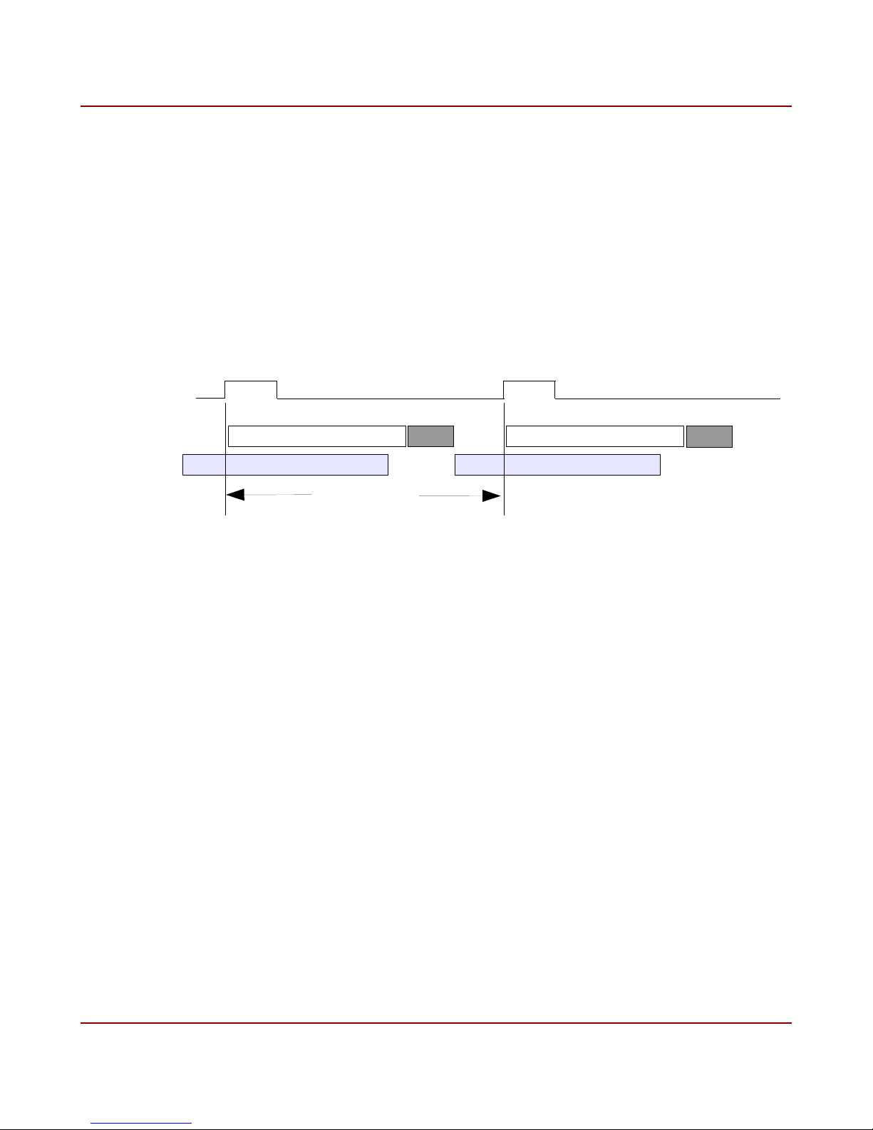
Dynamic Range exposure modes disabled, is shown in figure 12.
Exposure Time, Frame N
FOT
Exposure Time, Frame N+1 FOT Exposure Time, Frame N+2
Readout Time, Frame N
Frame Period
Readout Time, Frame N+1
Figure 12. Free-run exposure timing
In figure 12 the example timing is shown with the exposure time less than the readout time.
The fully pipelined architecture of the sensor allows for the next integration period to start
while the previous frame is being read out. There is a Frame Overhead Time (FOT) period
after exposure ends and before the readout of the frame begins. The next exposure cannot
start in the FOT period. The FOT varies with output formats and the image horizontal
resolution, see tables 7 and 8.
IO Industries Inc. www.ioindustries.com Revision 2.0
28
Flare CXP User's Manual
3.6 Edge-triggered programmable exposure
In edge-triggered programmable exposure mode an internal timer is used to control the
exposure of a frame, however, exposure does not start until the active edge of the input
trigger is seen. The primary exposure time is set using the Exposure 1 register, and the time
is set in microseconds. The frame period command has no effect in this mode. The range of
the exposure time will be set according to the maximum frame period allowed for the current
output format. The timing for this mode, with High Dynamic Range exposure modes disabled,
is shown in figure 13.
Input Trigger
(rising edge)
Exposure Time, Frame N FOT
Readout Time, Frame N-1
Frame Period
Exposure Time, Frame N+1
Readout Time, Frame N
FOT
Figure 13. Edge-triggered programmable exposure timing
Exposure starts when the active edge of the input trigger is seen. The active edge can be set
to rising or falling (Trigger Edge register). The trigger used can be the CoaXPress input
trigger received on the uplink signal (Trigger Source register, value 0x00000000) or the opto-
isolated input on the power connector (Trigger Source register, value 0x00000001). There is
a Frame Overhead Time (FOT) period after the exposure ends, same as free-run mode, and
then readout of the frame begins.
The minimum pulse width of the input trigger is 200 ns. The delay from the active edge of the
trigger to the start of exposure is approximately 200 ns.
Exposure of the next frame cannot start until the readout of the current frame begins. Also
exposure cannot end during the readout of the previous frame. The camera will not look for a
new trigger pulse until N microseconds have elapsed after readout begins, where N =
Readout Time - Exposure Time, if the exposure time is less than the readout time. With large
swings in exposure time it is likely that a trigger will be ignored to keep the correct timing on
the sensor.
IO Industries Inc. www.ioindustries.com Revision 2.0

29
Flare CXP User's Manual
3.7 Edge-triggered level-controlled exposure
In edge-triggered level-controlled exposure mode the exposure of the frame is controlled by
the active state of the input trigger. The frame period and exposure commands have no effect
in this mode. The High Dynamic Range exposure modes are not available in this mode. The
timing for this mode is shown in figure 14.
Frame Period
Input Trigger
(active high)
Exposure Time, Frame N Exposure Time, Frame N+1
FOT
FOT
Readout Time, Frame N-1
EOT EOT
Readout Time, Frame N
Figure 14. Edge-triggered level-controlled exposure timing
In this mode exposure starts when the input trigger transitions into the active state. Exposure
continues until the trigger transitions into the non-active state. The active state can be set to
low or high (Trigger Edge register).
There is a Frame Overhead Time (FOT) period after the sensor is triggered to stop integration
before the readout starts. When the sensor enters this FOT period there is a portion of time
where the photodiodes are still being exposed to light before the charge is transferred to the
storage elements. This Exposure Overhead Time (EOT), shown in figure 16, is a known
constant value and only depends on the CoaXPress output format. For programmable
exposure modes this time is included in the exposure time value.
The minimum pulse width is 1 µs.
Exposure of the next frame cannot start until the readout of the current frame begins. Also
exposure of the next frame cannot end during the readout of the current frame. To ensure
this condition is met the camera does not look for the end of exposure transition until the
readout of the current frame has completed.
IO Industries Inc. www.ioindustries.com Revision 2.0

30
Flare CXP User's Manual
3.8 Edge-triggered double exposure
In edge-triggered double exposure mode two frames are captured in rapid succession when a
single trigger edge is seen. This type of exposure mode is typically used in Particle Image
Velocimetry (PIV) and Particle Tracking Velocimetry (PTV) applications.
The first frame's exposure starts when the active trigger edge is detected and the exposure
time is set in the Exposure 1 register. The first frame corresponds to the 'short' exposure
frame. After the Frame Overhead Time period of the first frame, exposure of the second
frame automatically starts and the duration is equal to the frame readout time. The second
frame corresponds to the 'long' exposure frame. Starting the second frame exposure
automatically ensures the smallest time between the frame exposures. The timing of this
mode is shown in figure 15.
Trigger
(rising)
Programmed
Exposure Time,
Frame N
FOT
EOT
Automatic Exposure Time,
Frame N+1
Readout Time, Frame N
FOT
EOT
Programmed
Exposure Time,
Frame N
Readout Time, Frame N+1
FOT
EOT
Inter-frame Time
Figure 15. Edge-triggered double exposure timing
The inter-frame time between exposures is equal to the Frame Overhead Time (FOT) minus
the Exposure Overhead Time (EOT). See table 7 for the minimum inter-frame times for the
2M280 and table 8 for the 4M140. The minimum inter-frame time for the fastest 2M280
configuration is 21 µs. The minimum inter-frame time for the fastest 4M140 configuration is
48 µs.
IO Industries Inc. www.ioindustries.com Revision 2.0

31
Flare CXP User's Manual
3.9 Frame Period and Exposure
The frame period in free-run exposure mode is controlled with the Frame Period register,
address 0x400000078. The frame period is specified in microseconds. The minimum frame
period of the camera (maximum frame rate) is determined by the output format and the
resolution. Assuming free-run operation and that the exposure time is less than the readout
time the frame period is calculated as follows:
➢ Frame Period = Frame Overhead Time + Readout Time
The Frame Overhead Time (FOT) depends on the output format and the horizontal resolution.
Table 7 shows the FOT period for the 2M280 given the configuration of the camera. Table 8
shows the FOT period for the 4M140.
The Exposure Overhead Time (EOT) which is included in the programmable exposure times,
and which must be considered in the level-controlled exposure, is also shown in tables 7 and
8.
The readout time of a frame is equal to the number of lines in the output image multiplied by
the line time. Line times are also shown in tables 7 and 8.
IO Industries Inc. www.ioindustries.com Revision 2.0

32
Flare CXP User's Manual
CoaXPress Output
Format
Single Link
1 x CXP-3
10-bit
8-bit
Horizontal Resolution FOT
(in µs)
2048 ≥ HR > 1792 49 15 6.88 34
1792 ≥ HR > 1536 43 14 6.14 29
1536 ≥ HR > 1024 38 12 5.38 26
1024 ≥ HR > 896 42 15 3.44 27
896 ≥ HR > 768 37 14 3.07 23
768 ≥ HR 33 12 2.69 21
2048 ≥ HR > 1792 61 19 8.6 42
1792 ≥ HR > 1536 54 17 7.59 37
1536 ≥ HR > 1280 46 14 6.45 32
1280 ≥ HR > 1024 38 12 5.38 26
1024 ≥ HR > 896 52 19 4.3 33
896 ≥ HR > 768 46 17 3.79 29
EOT
(in µs)
Line Time
(in µs)
Minimum
Inter-Frame
Time (in µs)
768 ≥ HR > 640 39 14 3.23 25
640 ≥ HR 33 12 2.69 21
2048 ≥ HR > 1792 42 15 3.44 27
Dual Link
2 x CXP-3
8-bit
10-bit
1792 ≥ HR > 1536 37 14 3.07 23
1536 ≥ HR 33 12 2.69 21
2048 ≥ HR > 1792 52 19 4.3 32
1792 ≥ HR > 1536 46 17 3.79 29
1536 ≥ HR > 1280 39 14 3.23 25
1280 ≥ HR 33 12 2.69 21
Table 7. 2M280 FOT, EOT and line time periods
IO Industries Inc. www.ioindustries.com Revision 2.0

33
Flare CXP User's Manual
CoaXPress Output
Format
Single Link
1 x CXP-3
10-bit
8-bit
Horizontal Resolution FOT
(in µs)
2048 ≥ HR > 1792 83 15 6.88 68
1792 ≥ HR > 1536 74 14 6.14 60
1536 ≥ HR > 1024 65 12 5.38 53
1024 ≥ HR > 896 76 15 3.44 61
896 ≥ HR > 768 68 14 3.07 54
768 ≥ HR 60 12 2.69 48
2048 ≥ HR > 1792 104 19 8.6 85
1792 ≥ HR > 1536 92 17 7.59 75
1536 ≥ HR > 1280 78 14 6.45 64
1280 ≥ HR > 1024 65 12 5.38 53
1024 ≥ HR > 896 95 19 4.3 76
896 ≥ HR > 768 84 17 3.79 67
EOT
(in µs)
Line Time
(in µs)
Minimum
Inter-Frame
Time (in µs)
768 ≥ HR > 640 71 14 3.23 57
640 ≥ HR 60 12 2.69 48
2048 ≥ HR > 1792 76 15 3.44 61
Dual Link
2 x CXP-3
8-bit
10-bit
1792 ≥ HR > 1536 68 14 3.07 54
1536 ≥ HR 60 12 2.69 48
2048 ≥ HR > 1792 95 19 4.3 86
1792 ≥ HR > 1536 84 17 3.79 67
1536 ≥ HR > 1280 71 14 3.23 57
1280 ≥ HR 60 12 2.69 48
Table 8. 4M140 FOT, EOT and line time periods
IO Industries Inc. www.ioindustries.com Revision 2.0

34
Flare CXP User's Manual
The camera re-calculates the allowable range for the frame period when the output format or
resolution is changed. The camera will also adjust the current frame period to the new
minimum value. The range for the exposure times is also re-calculated, and if any current
setting is outside of the range it will be adjusted to the maximum time.
Frame rate calculation example:
➢ 2M280 in Dual Link 8-bit with a single window set to 1280 x 720 (no sub-sample)
• Frame Period = FOT + Readout Time
• = 33 µs + 720 (2.69 µs)
• = 1970 µs
• Frame Rate = 1 / Frame Period = 507.6 Hz
Note that the camera uses a 4.10 fixed point value for the line time to calculate the frame
period, so the actual frame period reported by the camera may be slightly different than those
calculated using floating point math.
Tables 9 shows some sample frame rates. Even with a larger FOT the 4M140 frame rates
are within ½ Hz of the 2M280 rates, at the same resolution.
Maximum Frame Rate
(Hz)
Single
8-bit
2048
x
2048*
82 134 133 255 280 756 1476
1600
x
1200*
1920
1080
x
Resolution
1280
x
720
1024
x
1024
640
x
480
320
x
240
Link
1 x CXP-3
56 108 106 141 224 756 1476
140 266 266 508 359 756 1476
Dual Link
10-bit
8-bit
2 x CXP-3
10-bit
112 215 212 508 359 756 1476
Table 9. Sample frame rates (* 4M140 only)
IO Industries Inc. www.ioindustries.com Revision 2.0

35
In programmable exposure modes the minimum exposure time is set to the Exposure
Overhead Time (EOT) plus 1 µs. In level-controlled exposure mode the minimum trigger
pulse is 1 µs resulting in the same minimum exposure times as the programmable modes.
Table 10 shows the minimum exposure times at full resolution. When the smallest horizontal
resolution 'zone' shown in tables 7 and 8 is used both the 2M280 and 4M140 have minimum
exposure times of 13 µs.
Flare CXP User's Manual
CoaXPress Output
Format
Single Link
1 x CXP-3
Dual Link
2 x CXP-3
Table 10. Minimum exposure times at full resolution
8-bit 16
10-bit 20
8-bit 16
10-bit 20
Min Exposure Time (in µs)
2M280/4M140
IO Industries Inc. www.ioindustries.com Revision 2.0

36
Flare CXP User's Manual
3.10 High Dynamic Range Modes
The HDR Mode register, address 0x40000074, is used to enable a High Dynamic Range
(HDR) exposure mode. The following modes are available:
➢ Interleaved (0x00000001)
➢ Piecewise (0x00000002)
Set the register to zero for normal exposure.
3.10.1 Interleaved HDR Exposure Mode
The Interleaved HDR mode is useful when there are both under and over exposed areas
within a frame. The Interleaved HDR mode will increase the dynamic ranges within these
dark and bright spots revealing detail that would not be seen otherwise.
In Interleaved HDR mode the even and odd lines have different exposure times. The odd
lines (1, 3, 5, ..) are exposed for the programmed time set by the Exposure 1 register. The
even lines (2, 4, 6, ...) are exposed for the programmed time set by the Exposure 2 register.
For a color camera the exposure times apply to pairs of lines to preserve the Bayer pattern.
One exposure time should be set high to see the detail in the dark areas of the image. The
second exposure time should be set low to see the detail in the bright areas of the image. An
'image fuse' filter is required on the host side to combine these two 'fields' into dramatic HDR
images.
Note an image fuse conversion filter comes standard with IO Industries Inc. CoreView©
and Streams© software packages.
For the best results the two fields should be separated and individually scaled up to the full
image size. For a color camera the Bayer demosaicing conversion should be done first. Next
the images can be 'fused' together by averaging the pixels from the two frames. Exposure
times can be used for the multiplication factor for each frame for a more accurate image fuse
(instead of 0.5 when simply averaging).
IO Industries Inc. www.ioindustries.com Revision 2.0

37
Flare CXP User's Manual
3.10.2 Piecewise HDR Exposure Mode
The Flare CXP camera can achieve a high optical dynamic range using the piecewise
exposure mode. This HDR mode is useful when there are over exposed areas within a
frame. The piecewise exposure mode will prevent pixels that are being exposed to large
amounts of light from over saturating while not influencing the response of the darker pixels.
Pixels which reach a programmed voltage will be clipped, while dark pixels will be left
untouched. The clipped pixels are held at this voltage for a programmed period of time. The
programmed voltage and exposure time correspond to a 'kneepoint' which creates another
piece, or slope, in the response curve. Up to two kneepoints can be programmed resulting in
3 slopes in the response curve. An example of piecewise exposure with 2 kneepoints and 3
slopes is shown in figure 16.
Pixel
Reset
Total Exposure
Time
Pixel
Sample
Vhigh
Vkp1
Vkp2
Vlow
Kneepoint 1
Exposure
Figure 16. Example pixel response in Piecewise HDR exposure mode
IO Industries Inc. www.ioindustries.com Revision 2.0
Kneepoint 2
Exposure

38
In figure 16 the green line represents a darker pixel that is not influenced by the kneepoint
settings and will have a normal response. The red line represents a bright pixel which would
be saturated in normal exposure. In piecewise exposure mode the bright pixel reaches the
first kneepoint voltage (Vkp1 in figure) and is held there until the first kneepoint exposure time
starts. The bright pixel continues exposure until it reaches the second kneepoint voltage
(Vkp2 in figure) where it is held again. Finally the pixel continues exposure when the start of
the second kneepoint exposure time is reached.
Table 11 summarizes the registers used in piecewise HDR exposure mode.
Flare CXP User's Manual
Register Range Description
HDR Mode
Exposure 1
Piecewise HDR
Number of Slopes
Piecewise HDR
Voltage 2 (pv2)
Exposure 2 (ex2)
Piecewise HDR
Voltage 1 (pv1)
Exposure 3 (ex3)
0 - 2 0 - Normal exposure
1 - Interleaved HDR mode
2 - Piecewise HDR mode
- Total exposure time in microseconds
2 - 3 Number of slopes.
2 - Kneepoint 1 enabled
3 - Kneepoints 1 and 2 enabled
0x40 - 0x7E Voltage setting for kneepoint 1.
Kneepoint 1 used in both slope cases.
Must be less than setting for kneepoint 2 when using
three slopes.
- Kneepoint 1 exposure time in microseconds.
Pixels are held at the pv2 voltage until (ex1 - ex2)
time has elapsed.
0x41 - 0x7F Voltage setting for kneepoint 2.
Must be greater than kneepoint 1.
- Kneepoint 2 exposure time in microseconds.
Pixels are held at the pv1 voltage until (ex1 - ex3)
time has elapsed.
Must be less than kneepoint 1 exposure time.
Table 11. Summary of registers used in Piecewise HDR exposure mode
IO Industries Inc. www.ioindustries.com Revision 2.0

39
Flare CXP User's Manual
3.11 Offset and Gain
3.11.1 Digital Offset
The dark level offset can be programmed using the Black Level Offset register, address
0x4000009C. The dark level at the output of sensor equals (70 + setting - 16383), Valid
offset setting range is 0 to 16383 (0x3FFF). The offset is a digital value added to the output
signal after the analog to digital conversion. Note that this register always reflects a 10-bit
pixel value range.
3.11.2 Analog Gain
An analog gain can can be applied using the Analog Gain register, address 0x400000A0.
Valid range is 0 to 3, and the corresponding gain values are shown in table 12. The analog
gain is applied by a Programmable Gain Amplifier (PGA) in every column before the analog to
digital conversion.
agn setting Gain
0 x 1 (0 dB)
1 x 1.2 (+1.6 dB)
2 x 1.4 (+2.9 dB)
3 x 1.6 (+4.1 dB)
Table 12. Analog gain settings
3.11.3 ADC Gain and Ramp Voltage
The sensors in the Flare CXP camera series use column ramp Analog to Digital Converters
(ADC). A ramp generator provides the ramp for the ADC reset and pixel measurements
(Correlated Double Sampling). The ADC Gain register can be used to change the slope of
this ramp, producing a 'digital gain'. The ADC Ramp Voltage register can be used to change
the starting voltage of the ramp generator signal. The ADC Gain setting of each camera is
calibrated at the factory to match a desired bit/e value and provide quality, high dynamic
range images. This are advanced settings and in general should not be changed.
The ADC Gain register is savable to the user sets. To load the factory calibrated value write
IO Industries Inc. www.ioindustries.com Revision 2.0

40
the register with a value of 0x00000000. With the parameter set to zero the factory value will
be loaded into the register. The ADC Ramp Voltage register can also be restored to the
factory setting by writing 0x00000000 to the register.
Flare CXP User's Manual
3.11.4 Digital Gain
A digital gain can be applied using the Digital Gain register, address 0x400000A4. The range
on the register value is between 16 and 256, and the digital gain applied to the pixels is as
follows:
➢ Digital Gain = (register value) / 16
The range of the digital gain is 1x (0 dB) up to 16x (+24 dB). The default setting is 16 giving
unity gain. The digital gain is applied to 10-bit pixels read out from the sensor.
3.12 Image Flipping
The output image from the Flare CXP camera can be flipped in the X and/or Y direction using
the Image Flip register, 0x400000B0. Table 13 shows the image flipping options.
Register
Description
Value
0x00000000 No image flipping
0x00000001 Image flipped in X direction
0x00000002 Image flipped in Y direction
0x00000003 Image flipped in both X and Y directions
Table 13. Imaging flipping settings
Figure 17 shows an example of image flipping.
IO Industries Inc. www.ioindustries.com Revision 2.0

41
Flare CXP User's Manual
NO FLIP
Figure 17. Image flipping example
Image flip in the X direction can be useful in an inspection application where two cameras are
placed on either side of the material flow. One camera can be set to image flip in the X
direction resulting in both cameras seeing the flow of material in the same direction. This may
simplify processing software algorithms and aid in an operators view of the material.
Image flip in the X and Y direction is useful when the camera has to be installed upside down.
X DIRECTION
Y DIRECTION X+Y DIRECTION
3.13 Test Pattern
The Flare CXP cameras have a test pattern mode to aid in testing connectivity between the
camera and a frame grabber. The options for the Test Pattern register, address 0x400000B8,
are shown in table 14.
Register Value Description
0x00000000 Image from sensor
0x00000001 Bayer color test pattern with moving lines (dynamic)
0x00000002 Bayer color test pattern without moving lines (static)
0x00000003 or
0x00000004
0x00000005 Dynamic monochrome test pattern
0x00000006 Static monochrome test pattern
Table 14. Test pattern settings
IO Industries Inc. www.ioindustries.com Revision 2.0
Reserved

42
In test pattern mode the camera frame rate is the same as in normal operation. All exposure
modes can be used when the test pattern is enabled. The test pattern image is always a
continuous image with a horizontal resolution set by the Horizontal Resolution register, and a
vertical resolution set by the total of the ROI-1 to ROI-8 Vertical Resolution registers for active
windows. The sensor is not disabled when the test pattern is on. Effects of some
commands, such as gain or high dynamic range modes, may not be visible in the test pattern
image, however, when the test pattern is disabled the images from the sensor will still be
affected.
The horizontal blanking period on the output of the test pattern is set to match the sensor line
rate.
The monochrome test pattern is a count up pattern. The counter starts at zero and counts up
to 0xFF (8-bit output configuration) or 0x3FF (10-bit output configuration), and then starts over
at zero again. Pixel values are repeated 8 times in both single and dual link configurations.
There is a moving horizontal and vertical line in the image. Every image the horizontal line
moves one line down compared to the previous image. The vertical line moves to the right by
8 pixels every image. Both lines are always present in the image. When the previous frame
has the horizontal line in the last line of the image, the next frame will have the horizontal line
in the first line. The moving lines help in testing the robustness of a system to bit errors by
creating high frequency change in the pixel values at the receiver.
Flare CXP User's Manual
A typical monochrome test pattern, with moving lines, is shown in figure 18.
IO Industries Inc. www.ioindustries.com Revision 2.0

43
Flare CXP User's Manual
Figure 18. Typical monochrome test pattern with moving lines (dynamic)
The bayer test pattern is very similar to the monochrome test pattern. The bayer pattern is a
count up pattern (0x00-0xFF in 8-bit mode and 0x000-0x3FF in 10-bit mode), but the count up
values are only assigned to one color plane at a time, while the other colors are set to zero.
The result is color bands with increasing brightness, starting with green, followed by blue and
finally red. The width of the color bands are 256 pixels wide. A typical bayer test pattern, with
moving lines, is shown in figure 19.
IO Industries Inc. www.ioindustries.com Revision 2.0

44
Flare CXP User's Manual
Figure 19. Typical Bayer test pattern with moving lines (dynamic)
IO Industries Inc. www.ioindustries.com Revision 2.0

45
Flare CXP User's Manual
3.14 Sensor Artifacts
The sensor manufacturer have identified some known artifacts with the CMV2000 and
CMV4000 sensors. The horizontal line and black sun artifacts are discussed in the following
sections, along with the algorithms built into the Flare CXP camera series to correct them.
For more information on these artifacts check the sensor manufacturer's website,
www.cmosis.com.
3.14.1 Horizontal Line
The horizontal line artifact may occur when exposure of the next frame starts during the
readout of the current frame. The effect is visible in the line addressed for readout when
exposure of the next frame begins. The effect is a positive or negative offset in the line
addressed for readout.
The horizontal line artifact has been observed in all output formats, but is most likely to occur
at higher frame rates. If the exposure time is set to the maximum value, for a given frame
period, the line will occur in the fourth line of the image.
During the readout period of a line there is a 'slot time' where the start of exposure can start
without producing the line effect. When the Horizontal Line Correction algorithm is enabled,
Horizontal Line Correction register set to 0x00000001 , the start of exposure will be delayed
to line up with the slot time. This will cause up to one line time period delay in the start of
exposure. The algorithm also handles the case when multiple exposure signals are used in
the High Dynamic Range exposure modes. To disable the algorithm set the Horizontal Line
Correction register to zero.
The slot time can vary slightly when different ADC ramp values are set. Use the HLC Adjust
register to move the programmed slot time. Values between 0x00000000 and 0x00000007
are added to the slot time, and when the parameter is set between 0x00000008 and
0x0000000F the parameter value minus 8 is subtracted from the slot time.
The analog gain setting also has an effect on the slot time, but this is handled in the camera
firmware automatically.
NOTE that when using the fastest sensor clock (smallest horizontal resolution zone from
tables 7 and 8) there may be no slot time where the line is invisible for both the CMV2000
and CMV4000 sensors.
The line number can be outputted from the camera by setting the Horizontal Line Correction
register to 0x00000002. The first two pixels of the last line are overwritten with the line
number, which ranges from 1 to N, where N is the last line in the image. The first pixel
represents the bottom 8 bits of the line count, if running in a 10-bit pixel depth the two most
significant bits are set to zero. The second pixel represents the upper 8 bits of the line count.
The line count is only 12 bits so the 4 most significant bits of the second pixel will be set to
IO Industries Inc. www.ioindustries.com Revision 2.0

46
zero when using a output pixel depth of 8 bits, and the 6 most significant bits will be set to
zero when using a 10-bit pixel depth.
To add an offset to the affected line set the Horizontal Line Correction register to 0x00000003.
In this mode the value stored in the HLC Add register will be added to the line.
IO Industries has tested Version 3 CMV4000 sensors and even with the in-sensor correction
algorithm the horizontal line artifact is still faintly present at the highest clock speeds.
Flare CXP User's Manual
3.14.2 Black Sun
The 'Black Sun' effect occurs when a very bright spot is aimed at the sensor, and the center of
the bright spot becomes dark instead of saturated white. This effect is caused by a saturated
reset level from the intense photons, resulting in a pixel value of zero from the Correlated
Double Sampling (CDS) step in the sensor.
This effect can be reduced or eliminated by reducing the light falling on the sensor by closing
the lens iris.
A second option built into the Flare camera firmware is to reduce the time between the pixel
reset and reset sample. Both the CMV2000 and CMV4000 have recommended defaults for
this time resulting in the best CDS result. When the Black Sun correction is turned on, Black
Sun Correction register set to 0x00000001, the time between the pixel reset and reset sample
is cut in half. This reduction in time will lessen or eliminate most Black Sun effects. To
disable the correction set the register to zero, default. The noise in the image will increase
with the Black Sun correction enabled.
3.15 Bad Pixel Replacement
Each camera is tested for defective pixels. These pixels can be 'dead' pixels (pixel value of
zero when sensor is fully saturated), 'hot' pixels (pixel value of 0x3FF when no light is hitting
sensor) and non-uniform pixels which react to light but vary significantly from the average of a
constant greyscale image.
The bad pixel replacement algorithm running in the camera can be enabled or disabled with
the Bad Pixel Correction register, 0x00000000 - disabled or 0x00000001 - enabled. By
default the algorithm is enabled. This command is saved to the user sets.
The algorithm replaces the bad pixels by using an average of neighboring pixels in the
horizontal direction. The list of bad pixels is stored in non-volatile memory in the camera,
which can be read and updated by users. The algorithm can correct up to 255 pixels.
IO Industries Inc. www.ioindustries.com Revision 2.0

47
Flare CXP User's Manual
3.16 Command Memory
The Flare CXP cameras use non-volatile memory to store up to 8 user command sets. To
save the current camera settings to one of these user sets, first set the User Set Selector
register to one of the user profiles, 1 to 8, and write a one to the User Set Save register. To
load from one of the user sets first set the User Set Selector register followed by a write of
one to the User Set Load register.
For convenience, and to easily remember what settings are programmed in a user set, the
Flare CXP cameras store a unique 32 byte name for each user set. The eight profile names
are stored in non-volatile memory and can ber read or written using the User Profile X Name
registers starting at address 0x50000000.
Also stored in the camera (in FPGA block ram) is a factory set of commands. To load the
factory profile set the User Set Selector register to zero and write a one to the User Set Load
register. For both the 2M280 and 4M140 the factory set of commands is full resolution,
normal free-run exposure in dual link 8-bit output format.
To set the power-up profile write the User Set Default Selector register with a value from 1 to
8 for one of the user profiles or 0 for the factory profile.
3.17 Camera Reset
Write a 1 to the Camera Reset register to fully reset a Flare CXP camera. When the reset
command is received the camera will reload various settings from memory (serial number,
ADC ramp values, etc), reload the bad pixel table, and then load the power up profile. The
discovery process on the frame grabber will have to be re-initiated after the reset completes.
3.18 Control Packet CRC
For the complexity, and to relax a closed system frame grabber design, the CRC value in the
uplink control packets are not checked by default. To enable the CRC check write a 1 to the
CRC Check Enable register, address 0x400000D4. The register is saveable to the user
profiles.
3.19 Device Discovery
To start imaging the Flare CXP cameras require the StreamPacketSizeMax bootstrap register
to be written with a non-zero, and a one must be written to the Start Acquisition register.
When sending out frames the led on the back of the camera will be flashing green.
IO Industries Inc. www.ioindustries.com Revision 2.0

48
Flare CXP User's Manual
4 Optional RS-485 Control
The Flare CoaXPress cameras can optionally be controlled through the RS-485 interface. A
simple ASCII command protocol is used. Below are some key points about the serial control:
➢ 8-bit, 9600-460800 baud, 1 stop bit and no parity.
➢ All sent commands end with a carriage return (0Dh), which can also be sent at any
time to reset the uart receiver state machine within the camera and return it to an
idle/ready state.
➢ Commands are 3 ASCII characters followed by the setting or simply a carriage return
when no settings are associated with the command.
➢ A space is sent between the command and the setting.
➢ All settings are in hexadecimal.
➢ All commands letters are in lower case (including settings hex values a-f).
➢ To query a command a carriage return is sent after the last command character.
➢ Successful commands return ACK (06h, generally seen as a dash (-) in terminal
programs), invalid or rejected commands return NAK (15h, generally seen as plus sign
(+) in terminal programs).
➢ A query returns the command, the current value, the minimum and maximum allowable
values within brackets, a carriage return and finally an ACK.
➢ Get camera parameters command (gcp) returns all command settings.
➢ Help command (hlp) returns list of all available commands and brief description.
➢ The CoaXPress configuration registers (StreamPacketSizeMax and AcquisitionStart)
must be disabled by setting the dcx command to 1. This command is savable to the
user sets.
Examples:
1 - Set frame period to 4000 µs (250 Hz):
Command: per 000fa0<CR>
Response: <ACK>
2 - Query frame period:
Command: per<CR>
Response: per 000fa0 (000b78,0f4240)<CR>
<ACK>
4.1 RS-485 Command Summary
IO Industries Inc. www.ioindustries.com Revision 2.0

49
Flare CXP User's Manual
Table 15 summarizes all available commands. The presence and size of a command's
parameters are shown with the letter 'Y' (see Format column). Each letter 'Y' represents a
hexadecimal digit from 0 to f.
Command Format Description Notes
CoaXPress
Output Format
Number of
Windows
Number of
Columns
Start Pixel 1 hs1 YYY Starting pixel for window 1 Start pixel of image when only using 1
Line Start 1 vs1 YYY Starting line for window 1 Start line of image when only using 1
Number of
Lines 1
Start Pixel 2 hs2 YYY Starting pixel for window 2
Line Start 2 vs2 YYY Starting line for window 2
Number of
Lines 2
cxf Y CoaXPress output format 0 – Single link 8-bit
1 – Single link 10-bit
2 – Dual link 8-bit
3 – Dual link 10-bit
Note all modes are CXP3 (3.125Gbps).
nwd Y Number of windows Up to 8 non-overlapping windows.
hrx YYY Horizontal resolution Applies to all windows. Must be mod 8,
with min of 16.
window.
window.
Minimum number of lines is 4.
vr1 YYY Number of lines for window 1 Number of lines in image when only
using 1 window.
vr2 YYY Number of lines for window 2
Start Pixel 3 hs3 YYY Starting pixel for window 3
Line Start 3 vs3 YYY Starting line for window 3
Number of
Lines 3
Start Pixel 4 hs4 YYY Starting pixel for window 4
Line Start 4 vs4 YYY Starting line for window 4
Number of
Lines 4
Start Pixel 5 hs5 YYY Starting pixel for window 5
Line Start 5 vs5 YYY Starting line for window 5
Number of
Lines 5
Start Pixel 6 hs6 YYY Starting pixel for window 6
vr3 YYY Number of lines for window 3
vr4 YYY Number of lines for window 4
vr5 YYY Number of lines for window 5
IO Industries Inc. www.ioindustries.com Revision 2.0

50
Flare CXP User's Manual
Command Format Description Notes
Line Start 6 vs6 YYY Starting line for window 6
Number of
Lines 6
Start Pixel 7 hs7 YYY Starting pixel for window 7
Line Start 7 vs7 YYY Starting line for window 7
Number of
Lines 7
Start Pixel 8 hs8 YYY Starting pixel for window 8
Line Start 8 vs8 YYY Starting line for window 8
Number of
Lines 8
Image Sub-
Sample
Exposure Mode mde Y Exposure modes In modes 1 and 2 set the per command
High Dynamic
Range
vr6 YYY Number of lines for window 6
vr7 YYY Number of lines for window 7
vr8 YYY Number of lines for window 8
sub Y Image sub-sample Reduces output resolution by 1/4.
Skip every second pixel and line (pairs
in color camera).
Does not modify hrx or vrx settings.
0 - off, 1 - on
to the expected trigger rate, which will
change the exposure range.
0 - Free Run Programmable Exposure
1 - External Trigger Programmable
Exposure
2 - External Trigger Level Exposure
3 - External Trigger Double Exposure
hdr Y High Dynamic Range mode 0 - Normal exposure
1 - Interleaved HDR mode
mde 0/1 - ex1 used for odd rows, ex2
used for even rows
mde 2/3 - not available
Frame Period per YYYYYY Frame period in microseconds Range of period depends on:
Exposure Time 1ex1 YYYYYY Primary exposure time in
Exposure Time 2ex2 YYYYYY Secondary exposure time in
IO Industries Inc. www.ioindustries.com Revision 2.0
microseconds
microseconds
2 - Piecewise HDR mode
mde 2/3 - not available
- output configuration
- resolution
- sub-sampling
Used in exposure modes 0 and 1.
Interleaved: exposure time of odd rows.
Piecewise: total exposure time.
Used in HDR modes only.
Interleaved: exposure of even rows.
Piecewise: kneepoint 1 exposure.

51
Flare CXP User's Manual
Command Format Description Notes
Exposure Time 3ex3 YYYYYY Tertiary exposure time in
microseconds
Number of
Slopes
Kneepoint 2 pv1 YY Kneepoint 2 voltage Sets kneepoint 2 voltage in Piecewise
Kneepoint 1 pv2 YY Kneepoint 1 voltage Sets kneepoint 1 voltage in Piecewise
Trigger Source
1
Trigger
Edge/Level 1
Digital Offset off YYYY Dark level offset applied to output
Analog Gain agn Y Analog gain applied by
pns Y Number of Piecewise HDR slopes Placements of kneepoints in X direction
tr1 Y Select primary trigger 0 – CXP trigger
te1 Y Trigger 1 Edge/Level select 0 - Falling (mde 1), Low (mde 2)
signal
Programmable Gain Amplifier (PGA)
in every column
Piecewise: kneepoint 2 exposure.
is controlled by Vlow settings, and
slope of segments is controlled by
exposure times.
HDR mode
HDR mode
1 - Opto-1
Exposure Modes:
0 - not used
1 - Starts primary exposure
2 - Starts and sets exposure time
3 - Starts 'dark frame' exposure
1 - Rising (mde 1), High (mde 2)
Valid off setting range is 0 to 16383
(0x3FFF). The dark level at the output
of sensor equal (70 + setting – 16383).
This value is always in terms of ADC
output of 10 bits.
0 - x1 gain (default)
1 - x1.2
2 - x1.4
3 - x1.6
Digital Gain dgn YYY Digital gain applied to sensor input
ADC Ramp adc YY ADC Ramp Range 24-59 (0x18-0x3B)
ADC Ramp
Voltage
Image Flipping flp Y Image flipping in X and/or Y
rmp YY ADC Ramp Voltage Range 102-115 (0x66-0x73)
IO Industries Inc. www.ioindustries.com Revision 2.0
up to 16x
direction
Range 16-256
Gain applied = (value)/16
Controls ramp generator starting
voltage for reset and pixel
measurements (CDS)
0 - No image flipping
1 - Image flipping in X
2 - Image flipping in Y
3 - Image flipping in X and Y

52
Flare CXP User's Manual
Command Format Description Notes
Opto-1 Output
Select
Test Pattern pat Y Enable test pattern 0 - off (image from sensor)
Horizontal Line
Correction
HLC
Adjustment
HLC
Add
Black Sun
Correction
Bad Pixel
Replacement
op1 Y Select output signal for Optocoupled
Output #1 (pin 10)
hlc Y Horizontal line artifact correction 0 – off
hrg Y Horizontal line 'slot time' adjustment Bit 3 - Sign bit ('0' - add, '1' - subtract)
hla Y Horizontal line add value Value added to line with artifact when
bsc Y Black sun artifact correction 0-off
bpx Y Bad pixel replacement algorithm 0-off
0 - Disabled (low)
1 - INTE1
2 - INTE2
3 – Internal frame valid
4 – internal line valid
1 – color bars on with moving lines
2 – color bars on without moving lines
3,4 – reserved
5 - mono ramp with moving lines
6 - mono ramp without moving lines
1 – on
2 – on, overwrite first two pixels of last
line with line number
3 – on, add hla value to line with artifact
Bits 2:0 - Value (0-7)
hlc is set to 3. Applies to internal 10-bit
data path, regardless of output pixel
depth.
1-on
1-on
Frame Number fnm Y Overwrite first 8 pixels with a frame
number
Disable
CoaXPress
Configuration
Check
Command CRC
Serial Port
Echo
dcx Y Disable CoaXPress configuration From the CXP interface the
crc Y Enable check of command packet
CRC
ech Y Enable serial port echo 0-off
0-off
1-on
StreamPacketSizeMax and
AcquisitionStart registers must be
written for the camera to start imaging.
With dcx set to 1 a packet size of 1024
bytes is automatically used, and
acquisition is enabled.
0-off
1-on
1-on
IO Industries Inc. www.ioindustries.com Revision 2.0

53
Flare CXP User's Manual
Command Format Description Notes
Serial Port
Baud Rate
Profile Number pnm Y Profile number Profile used when issuing a sav or a
Set Power-up
Profile
Save to User
Set
Load from User
Set
Reset Camera rst Complete camera reboot Loads from power-up profile.
Set Windows swd Applies current internal window
Camera Model cam Returns camera model Read only.
Serial Number ser Returns camera serial number Read only.
sbd Y Set serial port baud rate 0 – 9600
1 – 19200
2 – 38400
3 – 57600
4 – 115200 (factory default)
5 – 230400
6 – 460800
When changing baud rates an <ACK>
will be sent at the current baud rate
before switching.
lod command.
pup Y Power-up user set page or factory
page
sav Save current settings to user set
number in pnm command
lod Load settings from user set number
in pnm command
settings to output
0 - Factory page
1-8 - User set page
Firmware
Version
Get Camera
Parameters
Help hlp Returns summary of all commands
Open User Set
Name
Write User Set
Name
Save User Set
Name
Read User Set
Name
ver Returns FPGA firmware version Read only.
gcp Returns all current settings Returns all commands up to and
onm Y Open user set name for editing
wnm Y Write ASCII character to open user
set
snm Save currently opened user set
name
rnm Y Read user set name
Table 15. Command Summary
including pup.
Up to 32 characters per name
IO Industries Inc. www.ioindustries.com Revision 2.0

54
Flare CXP User's Manual
5 Accessories
Table 16 shows the accessories available for Flare CXP cameras.
Part Number Description
FLAREPWRNA Universal 12V power supply, includes power cord for North America
FLAREPWREU Universal 12V power supply, includes power cord for Europe
FLAREPWRUK Universal 12V power supply, includes power cord for United Kingdom
FLAREPWRIONA Universal 12V power supply with I/O connector, includes power cord
for North America
FLAREPWRIOEU Universal 12V power supply with I/O connector, includes power cord
for Europe
FLAREPWRIOUK Universal 12V power supply with I/O connector, includes power cord
for United Kingdom
FLAREPWRHR Flare Hirose HR10a
CABUSB1852M-DB9 USB-RS485 control cable 2m with DB9 connector
CABUSB4855M-DB9 USB-RS485 control cable 5m with DB9 connector
Table 16. Flare CXP accessories
6 Document Revision History
Revision Date Modification
1.0 (P1) 06/18/12 Preliminary release for use with Core/Flare kit only.
2.0 05/01/13 Release of CoaXPress compliant camera models.
Removed descriptions of preliminary 'Uart' style camera
models.
IO Industries Inc. www.ioindustries.com Revision 2.0

55
7 Firmware Revision History
Revision Date Modification
01 06/12/12 Preliminary release for use with Core/Flare kit only.
02/03 --/--/-- Internal testing.
04 05/01/13 Compliant CoaXPress firmware.
Flare CXP User's Manual
05 05/01/13
Added new options to remove horizontal line artifact (section
3.14.1).
IO Industries Inc. www.ioindustries.com Revision 2.0
 Loading...