

Quick Start Card
Packing List
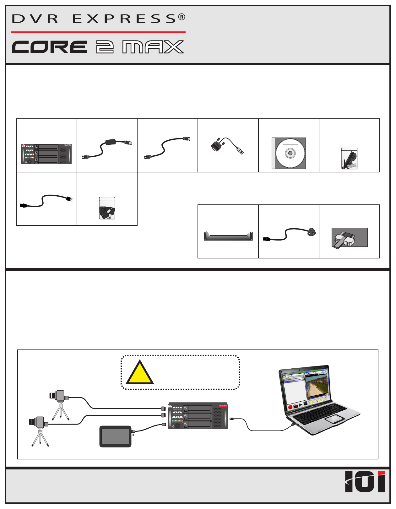
Standard Components (included with each DVR Express® Core 2 MAX recorder)
DVR Express®
Core 2 MAX
STATUS
PC ERROR
OPERATION
REC
PLAY
TIMING
PC
TC
GPS
STORAGE USED
AC Power Cord
(N. America 3-prong)
USB 3.0 to
eSATA Cable (3’)
Replacement:
P/N CABCOREUSB3
Keys for Rugged
Drive Cartridges (4)
eSATA Cable (6’)
Replacement:
P/N CABCORESATA
LTC Input Cable
Replacement:
P/N CABC2MAXLTC
Software and
Documentation CD
DVREXPR
ES S
®
CORE
Auxiliary I/O Cable Kit
(1) DB26 Male Connector
(1) DB26 Backshell Kit
Optional Accessories
Replacement:
P/N ACPWRCORDNA
Rack Mounting Shelf
P/N C2MAXSHELF
AC Power Cord
(EU or UK, 3-prong)
P/N ACPWRCRDEU
P/N ACPWRCRDUK
eSATA Cable Anchor Kit
Aluminum bracket secures
eSATA cable to recorder
eSA
P/N COREANCHOR
System Connections
The DVR Express® Core 2 MAX is configured and operated by a separate PC system. This
TA
system can be a workstation, laptop or tablet PC, as long as it has an available eSATA
or USB 3.0 port. Use the included eSATA cable or USB 3.0 to eSATA adapter to connect the
recorder to a free eSATA or USB 3.0 port on your PC.
Example Configuration
!
Video Camera(s)
Camera Interface Cable
HD-SDI Monitor
DVR Express® Core 2 MAX Quick Start Card v1.0
If using Camera Link cables,
the DVR power must be OFF
before making connections.
DVR Express® Core 2 MAX
STATUS
PC ERROR
OPERATION
REC
PLAY
TIMING
PC
TC
GPS
STORAGE USED
Page 1
eSATA Cable or
USB 3.0 to eSATA Adapter
Laptop Control PC
(must have one free eSATA or
USB 3.0 port per DVR)
INDUSTRIES
IO

Quick Start Card
Quick Start Checklist
A version of this Quick Start Checklist can be found in Section 1 of the DVR Express® Core 2 MAX User’s Manual, with
references to related sections of the manual. The User’s Manual can be found on the Software and Documentation CD.
1. Gather Required Components.
a) DVR Express® Core 2 MAX recorder.
b) Cameras, camera power supplies, video interface cables as needed.
c) eSATA cable or USB 3.0 to eSATA adapter.
d) Control PC with eSATA or USB 3.0 interface.
e) Software CD provided with recorder.
2. Connect Components.
a) Connect cameras to recorder using camera interface cables.
Note: Camera Link cameras are not hot-pluggable! Power off the camera or the recorder before making connections.
b) Connect power to cameras.
c) Connect recorder to Control PC using eSATA cable or USB3.0 to eSATA adapter.
d) Connect power to recorder.
e) The recorder immediately turns on when the power supply is connected. To turn off the recorder, press and hold the power
button for 2 seconds. It will shut off shortly after. As long as the power supply remains connected, the recorder can be turned
back on with a single press of the power button.
3. Install software on Control PC.
a) Insert the software CD in the PC.
b) Open the “Software” folder then the “CoreView” folder.
c) Run the installer to install CoreView and the necessary supporting files.
- 64-bit installer: core_x64.exe
- 32-bit installer: core.exe
Notes:
• The software must be installed using a Windows account that has Administrator privileges on the PC.
• The PC may need to be restarted following installation.
4. Launch CoreView from the Windows Start Menu.
64-bit: All Programs -> IO Industries -> DVR Express Core x64 -> CoreView
32-bit: All Programs -> IO Industries -> DVR Express Core -> CoreView
- If CoreView does not detect any recorders, check Windows Device Manager under the “Disk Drives” list. Each recorder should
appear in this list, or if the USB 3.0 to eSATA adapter is used, “ASMT 2115 USB Device” will be shown instead. For more
information, see "Detecting Connected Core(s)" in the User’s Manual.
5. Follow the steps in the “New Camera Wizard” to add cameras to CoreView.
6. Click the “Live” button on the DVR Controls to test camera connections
- Verify that images are being received from the attached cameras.
- For help, press “F1" to open the CoreVIew User Guide.
The system is now ready to record video!
Page 2DVR Express® Core 2 MAX Quick Start Card v1.0
INDUSTRIES
IO
 Loading...