

IO Industries High-Speed CMOS Area Scan Camera Series, CL Series, 2M360, 2M360MCL, 2M360CCL User Manual
...
TM
Flare
High-Speed CMOS Area Scan Camera Series
2M360 / 4M180
Camera Link
Revision 7.0
Copyright © 2011 IO Industries Inc. All rights reserved.
Flare is a pending trademark of IO Industries Inc.
User's Manual

2 Flare CL User's Manual
Notice
The material contained in this manual consists of information that is proprietary to IO
Industries Inc. and may only be used by the purchasers of the product and IO Industries Inc.
authorized distributors or resellers. IO Industries Inc. makes no warranty for the use of its
product and assumes no responsibility for any errors that may appear or for damages
resulting from the use of the information contained in this manual. IO Industries Inc. reserves
the right to make changes to this manual at any time without notice.
Warranty
The Flare CL product family is warranted for one (1) year from the date of purchase unless
otherwise agreed in writing. If the product proves to be defective during this warranty period,
IO Industries Inc. will, at its discretion, either repair or replace the product at no cost. In the
case where a new device is to be provided but the product has been discontinued, a product
with similar or better performance capabilities and features will be provided. This warranty
shall not apply to any damage, defect or failure caused by improper use or inadequate
maintenance of the product.
Certifications
FCC Class A Digital Device or Peripheral – Information to User
NOTE
This equipment has been tested and found to comply with the limits for a Class A digital
device, pursuant to Part 15 of the FCC Rules. These limits are designed to provide
reasonable protection against harmful interference when the equipment is operated in a
commercial environment. This equipment generates, uses, and can radiate radio frequency
energy and, if not installed and used in accordance with the instruction manual, may cause
harmful interference to radio communications. Operation of this equipment in a residential
area is likely to cause harmful interference in which case the user will be required to correct
the interference at his own expense.
WARNING
Changes or modifications not expressly approved by IO Industries Inc. could void the user's
authority to operate the equipment.
CE Compliance
This equipment has been certified to conform to the requirements of Council Directive
89/336/EC for electromagnetic compatibility and to comply with the following European
Standards:
• Immunity: EN55024:1998, A1:2001
• Emissions: EN55022:1998 Class A / CISPR 22:1997
All IO Industries Inc. products bearing the CE mark have been declared to be in conformance
with the applicable EEC Council Directives. Note that the use of interconnect cables that are
not properly grounded and shielded may affect CE compliance.
IO Industries Inc. www.ioindustries.com Revision 8.0

3 Flare CL User's Manual
About IO Industries Inc.
Established in 1991, IO Industries Inc. designs high performance digital imaging products for
applications in manufacturing, research, vehicle-mounted systems, and video game content
creation. Products include PC-based, standalone and peripheral DVR systems; and high
speed CMOS area scan digital cameras.
Contact Information
IO Industries Inc.
12-1510 Woodcock St.
London, Ontario
N6H 5S1 CANADA
Tel: (519) 663-9570
Fax: (519) 663-9571
Website: www.ioindustries.com
Sales: sales@ioindustries.com
Technical Support: support@ioindustries.com
IO Industries Inc. www.ioindustries.com Revision 8.0

4 Flare CL User's Manual
Table of Contents
1 Introduction...............................................................................................................................6
1.1 Camera Highlights............................................................................................................6
1.2 Sensor Specifications.......................................................................................................7
1.3 Cover Glass Transmittance..............................................................................................8
1.4 Monochrome Spectral Response.....................................................................................9
1.5 Color Spectral Response................................................................................................10
1.6 Bayer Pattern..................................................................................................................10
2 Mechanical.............................................................................................................................11
2.1 Mechanical Specifications..............................................................................................12
2.2 Lens Adapter...................................................................................................................12
2.3 Power..............................................................................................................................13
2.4 External Triggers.............................................................................................................14
2.5 LED Status Indicator.......................................................................................................16
2.6 Camera Link Connection................................................................................................16
3 Camera Control......................................................................................................................20
3.1 Command Summary.......................................................................................................21
3.2 Camera Link Output Format...........................................................................................29
3.3 Image Windowing...........................................................................................................30
3.4 Image Sub-Sample.........................................................................................................33
3.5 Exposure Mode...............................................................................................................34
3.5.1 Free-run programmable exposure..........................................................................34
3.5.2 Edge-triggered programmable exposure................................................................35
3.5.3 Edge-triggered level-controlled exposure...............................................................36
3.5.4 Edge-triggered double exposure.............................................................................37
3.6 Frame Period and Exposure ..........................................................................................38
3.7 High Dynamic Range Modes..........................................................................................44
3.7.1 Interleaved HDR Exposure Mode............................................................................44
3.7.2 Piecewise HDR Exposure Mode.............................................................................45
3.8 Offset and Gain...............................................................................................................47
3.8.1 Digital Offset............................................................................................................47
3.8.2 Analog Gain.............................................................................................................47
3.8.3 ADC Ramp...............................................................................................................47
3.8.4 Digital Gain..............................................................................................................48
3.9 Image Flipping................................................................................................................49
3.10 White Balance..............................................................................................................50
3.10.1 Auto White Balance (AWB)...................................................................................50
3.10.2 Tracking White Balance (TWB)............................................................................50
3.11 Auto Exposure Control (AEC)......................................................................................51
3.12 AWB and AEC Zones...................................................................................................52
3.13 Look Up Table..............................................................................................................54
IO Industries Inc. www.ioindustries.com Revision 8.0

5 Flare CL User's Manual
3.14 Lens Control..................................................................................................................54
3.15 Test Pattern...................................................................................................................55
3.16 Sensor Artifacts.............................................................................................................59
3.16.1 Horizontal Line.......................................................................................................59
3.16.2 Black Sun..............................................................................................................60
3.17 Bad Pixel Replacement................................................................................................60
3.18 Temperature..................................................................................................................61
3.19 Command Memory.......................................................................................................61
3.20 Camera Reset...............................................................................................................63
3.21 Reduced Line Rate.......................................................................................................63
4 Control Utility..........................................................................................................................65
4.1 Installation.......................................................................................................................65
4.2 Connect to Flare.............................................................................................................65
4.3 General Tab....................................................................................................................67
4.4 Exposure Tab..................................................................................................................67
4.5 Image Tab.......................................................................................................................73
4.6 Balance Tab....................................................................................................................74
4.7 Windows Tab...................................................................................................................76
4.8 Miscellaneous Tab..........................................................................................................77
4.9 Lens Tab..........................................................................................................................78
5 Firmware Update Utility..........................................................................................................80
6 Document Revision History....................................................................................................82
7 Firmware Revision History.....................................................................................................84
8 Appendix A CL Plus/Plus10 Pinouts.......................................................................................86
IO Industries Inc. www.ioindustries.com Revision 8.0

6 Flare CL User's Manual
1 Introduction
The Flare CL series is a family of high-speed CMOS area scan cameras designed for a broad
range of applications. The following Flare CL camera models are covered in this manual:
Model Resolution Color Output Format
2M360MCL
2048 x 1088
2M360CCL Bayer
4M180MCL
2048 x 2048
4M180CCL Bayer
Table 1. Covered Flare CL models
Monochrome
Monochrome
1.1 Camera Highlights
➢ Camera Link Base, Medium, Full and Plus (80-bit) output configurations
➢ Full resolution max. 340 fps (8-bit), 180 fps (10-bit) - 2M360
➢ Full resolution max. 180 fps (8-bit), 150 fps (10-bit) - 4M180
➢ Pipelined global shutter with Correlated Double Sampling (CDS)
➢ High sensitivity with low noise
➢ Multiple High Dynamic Range (HDR) modes
➢ 10-bit ADC resolution (selectable 8/10-bit output)
➢ Programmable and triggered exposure controlled
➢ Multiple windows with up to 8 separate Regions Of Interest (ROI)
➢ Advanced Auto Exposure Control (AEC)
➢ User programmable Lookup Table (LUT)
➢ Image Sub-sampling
➢ Fixed pattern noise and black level correction
➢ Rugged aluminum case
➢ C-mount lens adapter, or optionally use T- or CS-mount
➢ Minimum exposure times of 19 µs
➢ Analog (up to 1.6x) and digital (up to 16x) gains
➢ Low power (~ 3 W @ 12 V), Power Over Camera Link (PoCL)
Camera Link
IO Industries Inc. www.ioindustries.com Revision 8.0

7 Flare CL User's Manual
1.2 Sensor Specifications
Specification 2M360 4M180
Sensor CMOSIS CMV2000 CMOSIS CMV4000
Effective Pixels 2048 x 1088 2048 x 2048
Optical Format 2/3" 1"
Pixel Pitch 5.5 x 5.5 µm
Full Well Charge 13.5 Ke-
Conversion Gain 0.075 LSB/e-
Sensitivity 4.64 V/lux.s
Temporal Noise 13 e-
Dynamic Range 60 dB
2
Parasitic Light Sensitivity < 1/50000
Fill Factor > 50% (with micro lenses)
Quantum Efficiency > 50% @ 550nm (with micro lenses)
Dark Current Signal 125 e-/s (at 25ºC)
DSNU 3 LSB/s (10-bit)
Fixed Pattern Noise < 1 LSB RMS (10-bit)
PRNU < 1% of signal
Cover Glass Plain D263
Bad Columns
( > 100 pixels)
Bad Rows
( > 100 pixels)
Bad Pixels
Dark Image: > 6 x FPN Value
Bright Image: < 80% Swing
Table 2. Sensor specifications
max. 100 max. 200
0
0
IO Industries Inc. www.ioindustries.com Revision 8.0
8 Flare CL User's Manual
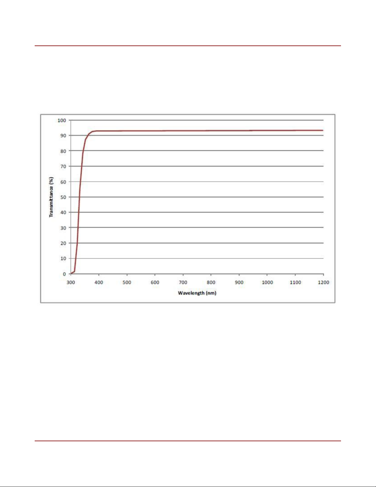
1.3 Cover Glass Transmittance
Plain D263 cover glass is used on all models. The glass transmittance is shown below. The
glass refraction index is 1.52.
Figure 1. Cover Glass Transmittance
IO Industries Inc. www.ioindustries.com Revision 8.0
9 Flare CL User's Manual
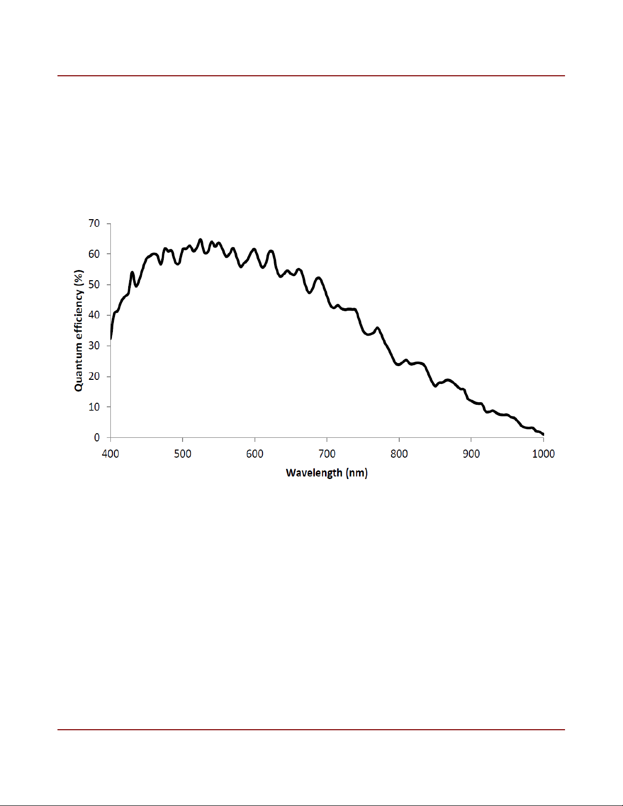
1.4 Monochrome Spectral Response
A typical spectral response of monochrome 2M360 and 4M180 cameras, with D263 cover
glass, is shown below.
Figure 2. Monochrome spectral response
IO Industries Inc. www.ioindustries.com Revision 8.0

10 Flare CL User's Manual
1.5 Color Spectral Response
A typical spectral response of color 2M360 and 4M180 cameras, with D263 cover glass and
color filters is shown below. Use an IR cut filter in the optical path to obtain good color
separation when using light with a NIR component. For most situations a filter which blocks
light above a wavelength of 675 nm produces the best results.
Figure 3. Color spectral response
1.6 Bayer Pattern
The 2M360 and 4M180 are both available in color. The Bayer pattern is shown in Figure 4.
G
Pixel
(1,1)
R
Pixel
(1,2)
Figure 4. Bayer color filter array pattern
IO Industries Inc. www.ioindustries.com Revision 8.0
B
Pixel
(2,1)
G
Pixel
(2,2)
11 Flare CL User's Manual
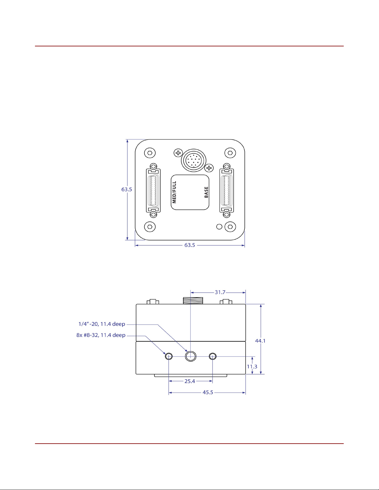
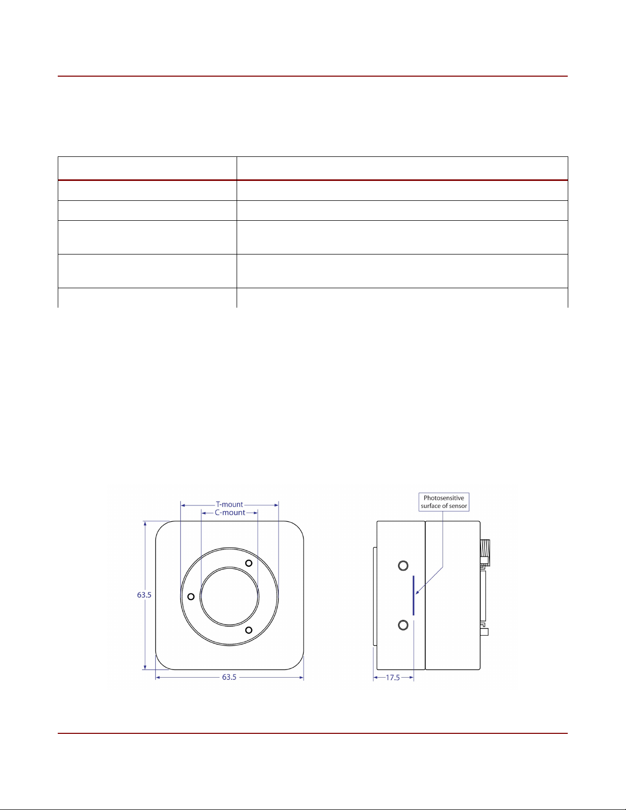
2 Mechanical
Camera housings are made with high precision from machined aluminum. Mechanical
drawings shown below.
Figure 5. Mechanical Drawings
IO Industries Inc. www.ioindustries.com Revision 8.0
12 Flare CL User's Manual
2.1 Mechanical Specifications
Summary of mechanical specifications shown below.
Specification Description
Size 63.5 mm x 63.5 mm x 44.1 mm
Weight 310 g
Mounting Holes Bottom - 1x 1/4"-20 (tripod)
All sides - 2 x #8-32, separation 1"
Power Connector 12-pin threaded Hirose
Mating connector part # HR10A-10TPA-12S(73)
Video Interface 2 x MDR26 Camera Link (standard)
Table 3. Mechanical specifications
Mounting holes on all sides of the camera, along with the image flipping feature, provides
many mounting options.
2.2 Lens Adapter
Aluminum C-mount lens adapter precisely calibrated to standardize focal length to sensor,
see Figure 6.
Figure 6. Lens adapter
IO Industries Inc. www.ioindustries.com Revision 8.0

13 Flare CL User's Manual
The position of the lens adapter is set using specialized equipment to ensure the proper back
focus of each camera. Three set screws (M2.5 - 1.3mm hex) on the front of the adapter are
used to firmly hold the ring adapter in place. In most cases it is not recommended to change
the position of the adapter ring. In rare cases the back focus can be adjusted to improve
image sharpness when using lower cost zoom lenses or custom optics.
The size of adapter ring is T-mount, with standard threading. It is possible to use a T-mount
extension tube with T-mount lenses; commonly Telephoto Zoom and Telescope lenses.
Between the adapter ring and the sensor there is another section of C-mount threading. With
a spacer this section can be used for a CS-mount lens. This section can also be used to
insert a filter in the optical path of the camera. An IR cut filter can be placed in a color camera
which will work with any lens type, avoiding the cost of having filters for every type of lens
used. Also a UV filter can be used which makes cleaning the camera easier, avoiding all
contact with the sensor glass itself. It is recommended to order the camera with the filter
in place, since the back focus changes with a filter installed, and it will be installed in a
clean environment. Contact IO Industries for filter options.
2.3 Power
Flare CL cameras are powered using a +12 V ± 10% DC power source. The power connector
is shown in Figure 7, and the pinout is shown in Table 4.
The camera can optionally be powered via 'Power Over Camera Link' (PoCL) from a
compliant frame grabber on the CL Base connector only. It is stongly recommended to
remove the power adapter from the camera power connector when using the camera in a
PoCL configuration. Applying power from both sources may damage the camera.
IO Industries Inc. www.ioindustries.com Revision 8.0
14 Flare CL User's Manual
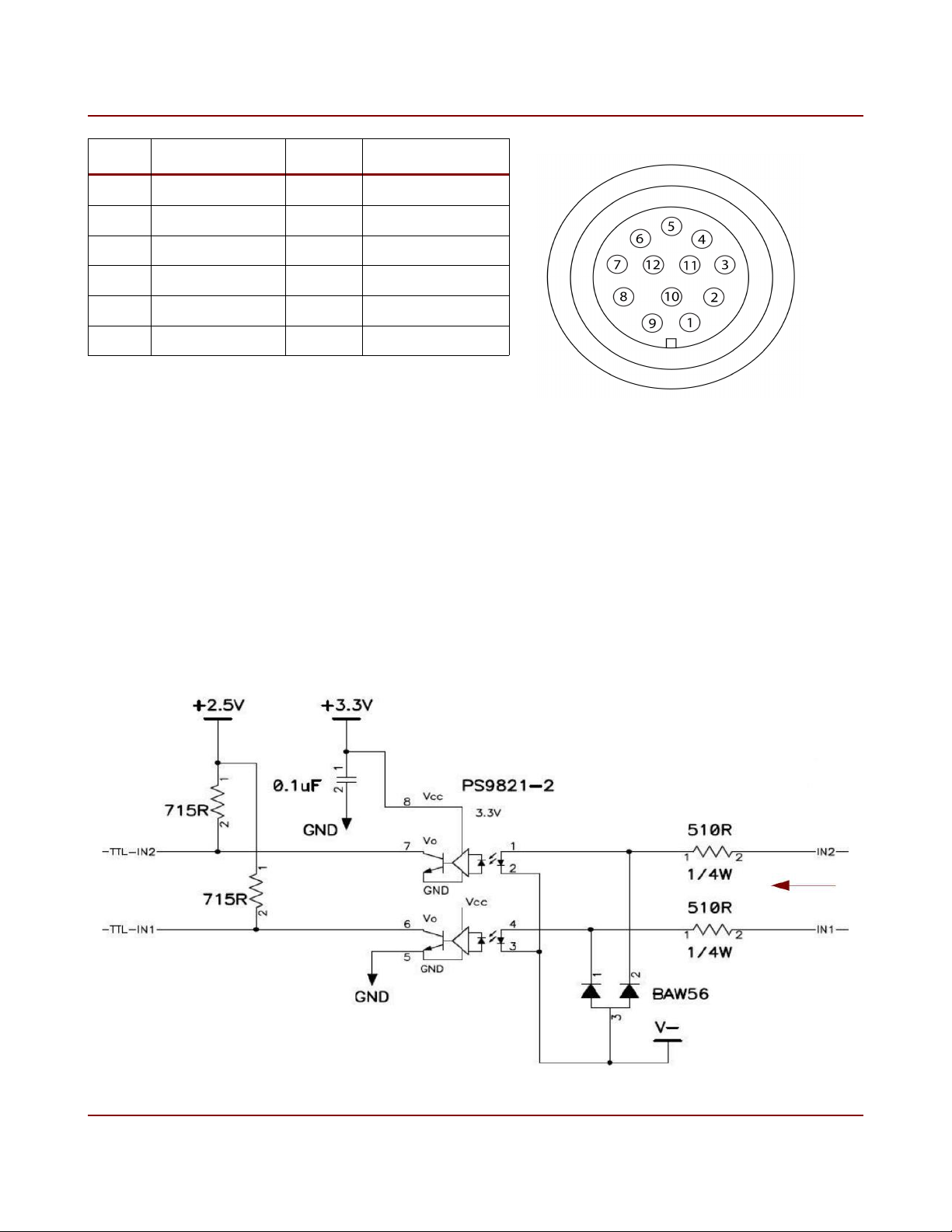
Pin Description Pin Description
1 Trigger Input 1 7 Trigger Return
2 Trigger Input 2 8 Trigger VCC
3 12 V 9 Trigger Out 2
4 12 V 10 Trigger Out 1
5 GND 11 NC
6 GND 12 NC
Table 4. Power connector pinout
Figure 7. Power connector
2.4 External Triggers
There are two opto-isolated inputs on the power connector (pins 1 and 2). Only ground must
be provided as a reference for the inputs. The voltage range on the inputs is 4.5 to 7.5 V, and
the input delay is approximately 100 ns. The input current range is 6 to 12 mA per input. The
circuit diagram for the opto-isolated inputs is shown in figure 8.
Figure 8. Opto-isolated inputs circuit diagram
IO Industries Inc. www.ioindustries.com Revision 8.0
15 Flare CL User's Manual
The opto-isolated input circuit uses a high-speed photocoupler from Renesas Technology
Corporation, part # PS9821-2.
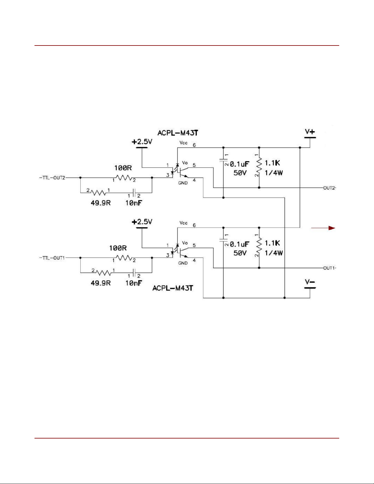
There are two opto-isolated outputs on the power connector (pins 10 and 9). Power (4.5 to
15 V) and ground must be provided for these outputs. The maximum output delay is
approximately 1 µs. An external pull-up reisistor is not required, but if one is used it must be
greater than 2 kΩ. The circuit diagram for the opto-isolated outputs is shown in figure 9.
Figure 9. Opto-isolated outputs circuit diagram
The opto-isolated output circuit uses a single channel high speed digital optocoupler per
output (Avago Technologies part # ACPL-M34T).
IO Industries Inc. www.ioindustries.com Revision 8.0
16 Flare CL User's Manual
2.5 LED Status Indicator
A tri-color (orange/green/red) LED on the back of the camera is used to indicate operational
status. Table 5 summarizes the operating states indicated by the LED.
LED State Description
Orange Camera is initializing (approximately 5-6 seconds after power is applied)
Green Camera is operational and functioning correctly
Flashing Green Executing long command
Flashing Red Error accessing user set memory
Red Fatal error
Table 5. LED status
2.6 Camera Link Connection
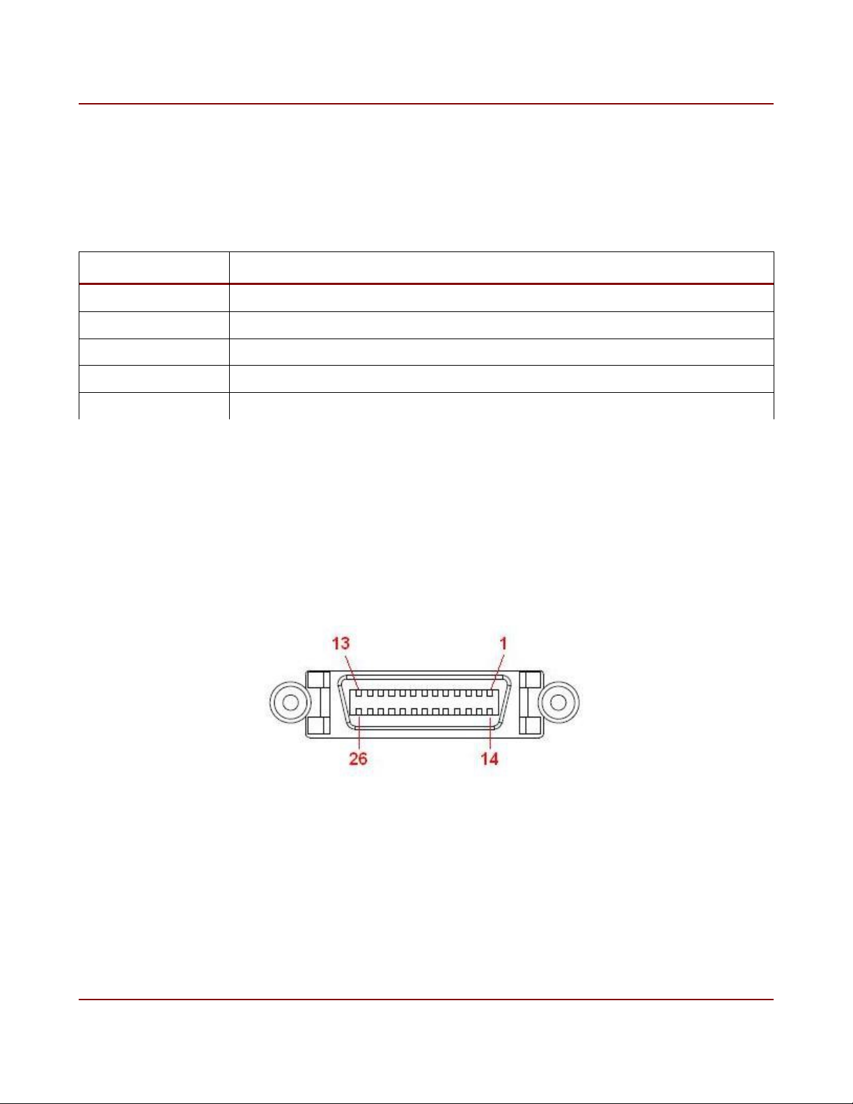
The Flare CL camera series uses two standard 26-pin MDR connectors specified in the
Camera Link Specification. The female 26-pin MDR connectors used on the Flare CL
cameras is shown in Figure 10.
Figure 10. Camera Link 26-pin MDR connector
All pinouts and bit assignments are in accordance with the Camera Link specification. The
pin configuration for the base connector is shown in Table 6.
IO Industries Inc. www.ioindustries.com Revision 8.0

17 Flare CL User's Manual
Pin Designation Description Direction Pin Designation Description Direction
1 Inner Shield Cable Inner Shield N/A 14 Inner Shield Cable Inner Shield N/A
2 X0- Serial Data Output 15 X0+ Serial Data Output
3 X1- Serial Data Output 16 X1+ Serial Data Output
4 X2- Serial Data Output 17 X2+ Serial Data Output
5 XCLK- Pixel Clock Output 18 XCLK+ Pixel Clock Output
6 X3- Serial Data Output 19 X3+ Serial Data Output
7 SerTC+ Serial RX Input 20 SerTC- Serial RX Input
8 SerTFG+ Serial TX Output 21 SerTFG+ Serial TX Output
9 CC1- Camera Control Input 22 CC1+ Camera Control Input
10 CC2+ Camera Control Input 23 CC2- Camera Control Input
11 CC3- Camera Control Input 24 CC3+ Camera Control Input
12 CC4+ Camera Control Input 25 CC4- Camera Control Input
13 Inner Shield Cable Inner Shield N/A 26 Inner Shield Cable Inner Shield N/A
Table 6. CL Base connector pin configuration
The pin configuration for the medium/full connector is shown in Table 7.
Pin Designation Description Direction Pin Designation Description Direction
1 Inner Shield Cable Inner Shield N/A 14 Inner Shield Cable Inner Shield N/A
2 Y0- Serial Data Output 15 Y0+ Serial Data Output
3 Y1- Serial Data Output 16 Y1+ Serial Data Output
4 Y2- Serial Data Output 17 Y2+ Serial Data Output
5 YCLK- Pixel Clock Output 18 YCLK+ Pixel Clock Output
6 Y3- Serial Data Output 19 Y3+ Serial Data Output
7 - - - 20 - - -
8 Z0- Serial Data Output 21 Z0+ Serial Data Output
9 Z1- Serial Data Output 22 Z1+ Serial Data Output
10 Z2- Serial Data Output 23 Z2+ Serial Data Output
11 ZCLK- Pixel Clock Output 24 ZCLK+ Pixel Clock Output
12 Z3- Serial Data Output 25 Z3+ Serial Data Output
13 Inner Shield Cable Inner Shield N/A 26 Inner Shield Cable Inner Shield N/A
Table 7. CL Medium/Full connector pin configuration
IO Industries Inc. www.ioindustries.com Revision 8.0
18 Flare CL User's Manual
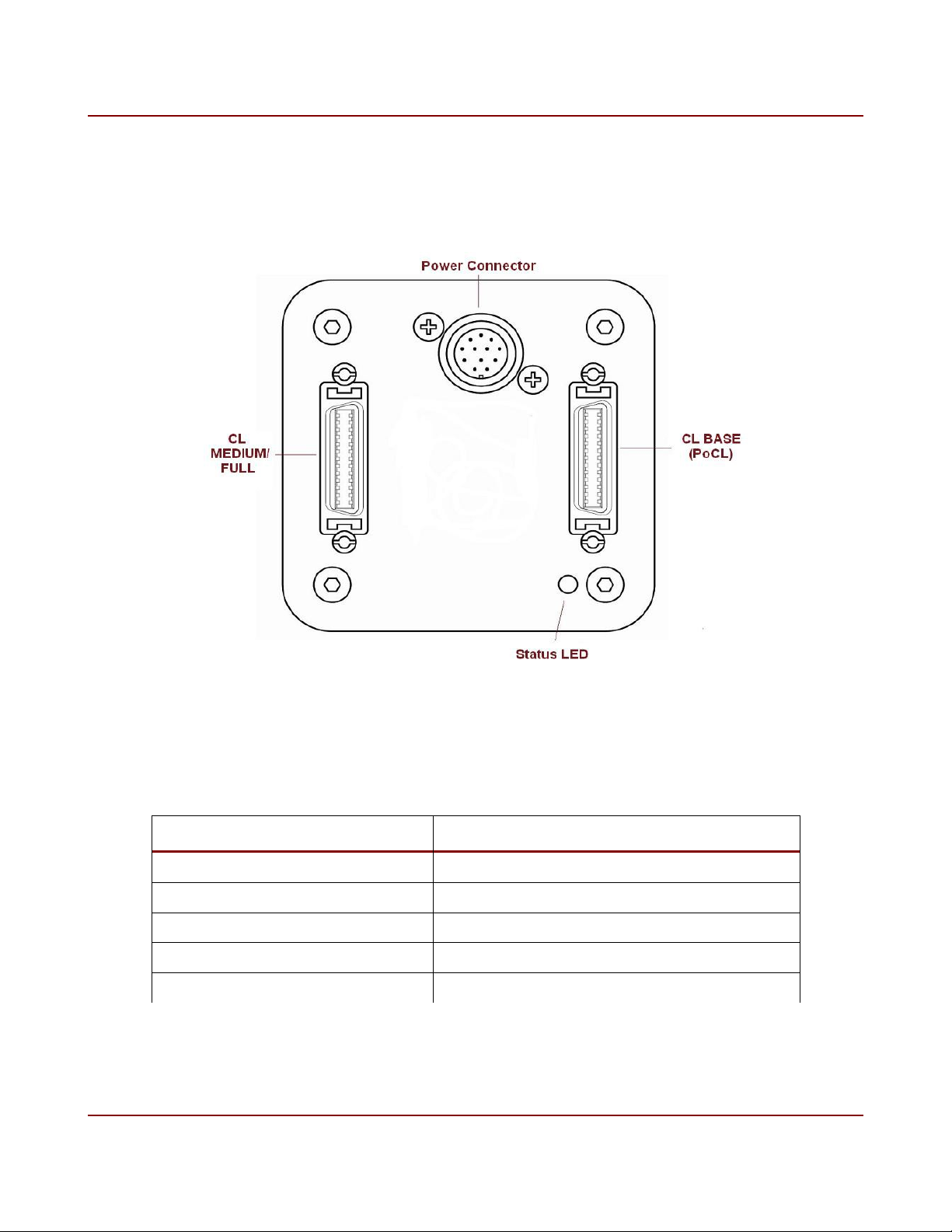
The CL Base connector is on the right hand side when looking at the back of the camera, with
the power connector at the top. The CL Medium/Full connector is on the left. Figure 11 shows
the back view of the camera.
Figure 11. Back view of Flare CL camera
The supported Camera Link output configurations are shown in Table 8.
Camera Link Configuration Output
Base 2x8-bit, 3x8-bit and 2x10-bit
Medium 4x8-bit and 4x10-bit
Full 8x8-bit
Plus10 (80-bit) 8x10-bit
Plus (80-bit) 10x8-bit
Table 8. Supported Camera Link configurations
IO Industries Inc. www.ioindustries.com Revision 8.0

19 Flare CL User's Manual
The camera supports the popular 80-bit extension to the Camera Link Specification. Camera
Link Plus throughout this manual will be referring to the 10x8-bit output configuration of the
camera. In addition to the CL Plus output format, the Flare CL camera also has an 8x10-bit
output configuration to reach higher speeds with a pixel depth of 10-bit. Throughout this
manual the 8x10-bit output mode will be referred to as CL Plus10. See Appendix A, Table
27, for the bit mapping of CL Plus. See Appendix A, Table 28, for the bit mapping of CL
Plus10.
The Camera Link pixel clock is 80 MHz.
IO Industries Inc. www.ioindustries.com Revision 8.0

20 Flare CL User's Manual
3 Camera Control
Control of the camera settings is done through the Camera Link serial port. A simple ASCII
protocol is used. Below are some key points about the serial control:
➢ 8-bit, 9600 baud (power-up default), 1 stop bit and no parity
➢ All sent commands end with a carriage return (0Dh), which can also be sent at any
time to reset the uart receiver state machine within the camera and return it to an
idle/ready state.
➢ Commands are 3 ASCII characters followed by the setting or simply a carriage return
when no settings are associated with the command.
➢ A space is sent between the command and the setting.
➢ All settings are in hexadecimal.
➢ All commands letters are in lower case (including settings hex values a-f).
➢ To query a command a carriage return is sent after the last command character.
➢ Successful commands return ACK (06h, generally seen as a dash (-) in terminal
programs), invalid or rejected commands return NAK (15h, generally seen as plus sign
(+) in terminal programs).
➢ A query returns the command, the current value, the minimum and maximum allowable
values within brackets, a carriage return and finally an ACK.
➢ Get camera parameters command (gcp) returns all command settings.
➢ Help command (hlp) returns list of all available commands and brief description.
Examples:
1 - Set frame period to 4000 µs (250 Hz):
Command: per 000fa0<CR>
Response: <ACK>
2 - Query frame period:
Command: per<CR>
Response: per 000fa0 (000b78,0f4240)<CR>
<ACK>
IO Industries Inc. www.ioindustries.com Revision 8.0

21 Flare CL User's Manual
3.1 Command Summary
Table 9 summarizes all available commands. The presence and size of a command's
parameters are shown with the letter 'Y' (see Format column). Each letter 'Y' represents a
hexadecimal digit from 0 to f.
Command Format Description Notes
CL Output
Format
Section 3.2
Number of
Windows
clf Y Camera Link output format CL Base: 0 - 2x8-bit, 1 - 2x10-bit, 2 -
3x8-bit
CL Medium: 3 - 4x8-bit, 4 - 4x10-bit
CL Full: 5 - 8x8-bit
CL Plus10: 6 - 8x10-bit
CL Plus: 7 - 10x8-bit
nwd Y Number of windows Up to 8 non-overlapping windows.
Section 3.3
Number of
Columns
Start Pixel 1 hs1 YYY Starting pixel for window 1 Step depends on CL output mode.
Line Start 1 vs1 YYY Starting line for window 1 Start line of image when only using 1
Number of
Lines 1
Start Pixel 2 hs2 YYY Starting pixel for window 2
hrx YYY Horizontal resolution Applies to all windows.
clf 0, 1, 3, 4, 5 and 6 - must be mod8
(010h-800h)
clf 2 - must be mod12 (018h-804h)
clf 7 - must be mod10 (014h-802h)
Start pixel of image when only using 1
window.
window.
Minimum number of lines is 4.
vr1 YYY Number of lines for window 1 Number of lines in image when only
using 1 window.
Line Start 2 vs2 YYY Starting line for window 2
Number of
Lines 2
Start Pixel 3 hs3 YYY Starting pixel for window 3
Line Start 3 vs3 YYY Starting line for window 3
Number of
Lines 3
Start Pixel 4 hs4 YYY Starting pixel for window 4
Line Start 4 vs4 YYY Starting line for window 4
vr2 YYY Number of lines for window 2
vr3 YYY Number of lines for window 3
IO Industries Inc. www.ioindustries.com Revision 8.0

22 Flare CL User's Manual
Command Format Description Notes
Number of
Lines 4
Start Pixel 5 hs5 YYY Starting pixel for window 5
Line Start 5 vs5 YYY Starting line for window 5
Number of
Lines 5
Start Pixel 6 hs6 YYY Starting pixel for window 6
Line Start 6 vs6 YYY Starting line for window 6
Number of
Lines 6
Start Pixel 7 hs7 YYY Starting pixel for window 7
Line Start 7 vs7 YYY Starting line for window 7
Number of
Lines 7
Start Pixel 8 hs8 YYY Starting pixel for window 8
Line Start 8 vs8 YYY Starting line for window 8
Number of
Lines 8
Image Sub-
Sample
vr4 YYY Number of lines for window 4
vr5 YYY Number of lines for window 5
vr6 YYY Number of lines for window 6
vr7 YYY Number of lines for window 7
vr8 YYY Number of lines for window 8
sub Y Image sub-sample Reduces output resolution by 1/4.
Section 3.4
Exposure Mode
Section 3.5
mde Y Exposure Modes:
0 - Free Run Programmable
Exposure
1 - External Trigger Programmable
Exposure
2 - External Trigger Level Exposure
3 - External Trigger Double
Exposure
Skip every second pixel and line (pairs
in color camera).
Does not modify hrx or vrx settings.
0 - off, 1 - on
High Dynamic
Range
Section 3.7
Frame Period per YYYYYY Frame period in microseconds Range of period depends on:
hdr Y High Dynamic Range mode 0 - Normal exposure
1 - Interleaved HDR mode
mde 0/1 - ex1 used for odd rows, ex2
used for even rows
mde 2/3 - not available
2 - Piecewise HDR mode
mde 2/3 - not available
- camera link configuration
- resolution
IO Industries Inc. www.ioindustries.com Revision 8.0

23 Flare CL User's Manual
Command Format Description Notes
Section 3.6
Exposure Time
1
ex1 YYYYYY Primary exposure time in
microseconds
Section 3.6
Exposure Time2ex2 YYYYYY Secondary exposure time in
microseconds
Exposure Time3ex3 YYYYYY Tertiary exposure time in
microseconds
Number of
Slopes
pns Y Number of Piecewise HDR slopes Placements of kneepoints in X direction
Section 3.7.2
Kneepoint 2 pv1 YY Kneepoint 2 voltage Sets kneepoint 2 voltage in Piecewise
Kneepoint 1 pv2 YY Kneepoint 1 voltage Sets kneepoint 1 voltage in Piecewise
Trigger Select 1 tr1 Y Select primary trigger 0 - CC1
- sub-sampling
Used in exposure modes 0 and 1.
Interleaved: exposure time of odd rows.
Piecewise: total exposure time.
Used in HDR modes only.
Interleaved: exposure of even rows.
Piecewise: kneepoint 1 exposure.
Piecewise: kneepoint 2 exposure.
is controlled by Vlow settings, and
slope of segments is controlled by
exposure times.
HDR mode
HDR mode
1 - CC2
2 - CC3
3 - CC4
4 - Opto-1
5 - Opto-2
Exposure Modes:
0 - not used
1 - Starts primary exposure
2 - Starts and sets exposure time
3 - Starts 'dark frame' exposure
Trigger
Edge/Level 1
Digital Offset
te1 Y Trigger 1 Edge/Level select 0 - Falling (mde 1), Low (mde 2)
1 - Rising (mde 1), High (mde 2)
off YYYY Dark level offset applied to output
signal
Dark Level = (70 + YYYY - 16383)
Section 3.8
Analog Gain
Section 3.8
Digital Gain
agn Y Analog gain applied by
Programmable Gain Amplifier (PGA)
in every column
dgn YYY Digital gain applied to sensor input
up to 16x
0 - x1 gain (default)
1 - x1.2
2 - x1.4
3 - x1.6
Range 16-256
Gain applied = (value)/16
Section 3.8
ADC Ramp adc YY ADC Ramp Range 24-59 (18-3Bh)
IO Industries Inc. www.ioindustries.com Revision 8.0

24 Flare CL User's Manual
Command Format Description Notes
Section 3.8
ADC Ramp
Voltage
Image Flipping
Section 3.9
Lookup Table lut Y Apply lookup table 0000 – off
AWB/AEC
Zone 1
AWB/AEC
Zone 2
rmp YY ADC Ramp Voltage Range 102-115 (66-73h)
Controls ramp generator starting
voltage for reset and pixel
measurements (CDS)
flp Y Image flipping in X and/or Y
direction
az1 YYYY Image divided into 64 zones (8x8).
Full image or selected zones can be
used for auto white balance and
auto exposure control. Commands
az1 - az4 are 'one-hot' enable bits
for the zones. Command az1
represents the first 16 zone (0-15),
starting in the top left (bit 0) of
image.
az2 YYYY Zones 16 (bit 0) - 31 0 - disable
0 - No image flipping
1 - Image flipping in X
2 - Image flipping in Y
3 - Image flipping in X and Y
0001 – LUT 1
0010 – LUT 2
0011 – LUT 3
0100 – LUT 4
0 - disable
1- enable
1- enable
AWB/AEC
Zone 3
AWB/AEC
Zone 4
Zone Overlay azo Y Overlay to show enabled zones.
White Balance
Multipliers
Tracking White
Balance
TWB Speed tws Y Adjusts the speed of auto white
AEC Minimum amn YYYY Minimum value for exposure used Range = (min ex1, amx)
az3 YYYY Zones 32 (bit 0) - 47 0 - disable
1- enable
az4 YYYY Zones 48 (bit 0) - 63 0 - disable
1- enable
0 - off
Disable zones are grey in overlay
(alpha blend with 10-bit pixel value
0x800).
wbm
BBBRRR
twb Y Adjusts red and blue multipliers
Two 2.10 unsigned fixed point
multipliers for blue and red pixels
(wbm) every frame to keep white
balance. Size of adjustments
depends on speed command (tws).
Current parameter values for wbm
are updated and can be queried.
balance multiplier changes
1- on
Individual multiplier range 0x001 - 0xfff
(0.00097 - 3.99902)
0 - off
1 - on, using full image
2 - on, using enabled zones
Range 0 (slowest) - 3 (fastest)
Default = 2
IO Industries Inc. www.ioindustries.com Revision 8.0

25 Flare CL User's Manual
Command Format Description Notes
Exposure by auto exposure control Minimum value equal to min of ex1
command. Maximum value equal to
current amx setting. When amn = amx,
only gain will be used resulting in ±EV
type control if small range of gain used
centered around 1x
AEC Maximum
Exposure
AEC Minimum
Aperture
AEX Maximum
Aperture
AEC Minimum
Gain
AEC Maximum
Gain
AEC Target aet YYY Target luma value for auto exposure
AEC Area aea Y Area to use for auto exposure
AEC Speed aes Y Adjusts the speed of auto exposure
AEC Enable aex Y Auto exposure mode selection 0 - off
Lens Aperture ape YY Set lens aperture - Parameter range varies from lens to
amx YYYY Maximum value for exposure used
by auto exposure control
aan YY Minimum value for lens aperture
used by auto exposure control
aax YY Maximum value for lens aperture
used by auto exposure control
adn YYYY Minimum value for digital gain used
by auto exposure control
adn YYYY Maximum value for digital gain used
by auto exposure control
control
control
changes
Same range as ex1
Range = (0, aax)
Same range as ape
Range = (0x0001, adx)
Same range as dgn
Range 0x001 to 0x3FF
Luma value is calculated using average
red, green and blue pixels over the
whole image or enabled zones (aea).
Luma is calculated according to
ITU.REC709:
Y = 0.2126R + 0.7152G + 0.0722B
0 - full image
1 - enabled zones
Range 0 (slowest) - 3 (fastest)
Default = 2
1 - auto exposure
2 - auto exposure and digital gain
3 - auto exposure and aperture
4 - auto exposure, aperture and digital
gain
lens
- 0 corresponds to a fully open aperture
Lens Focus
Step
Lens Focus to
Infinity
Lens Focus to
Zero
Lens Focus fsi Step lens focus towards infinity - Steps the lens focus towards infinity
fst YY Set focus step size - Parameter range 04h to C8h
- Effect of step size varies from lens to
lens
fci Set lens focus to infinity - Moves lens focus to infinity position
fcz Set lens focus to minimum - Moves the lens focus to its minumum
position
IO Industries Inc. www.ioindustries.com Revision 8.0

26 Flare CL User's Manual
Command Format Description Notes
Step Infinity using the current focus step size
Lens Focus
Step Zero
Lens Reset lnr Reset EF lens control
Lens Status lns Y Report lens status 0 - Lens ready (0 - no lens, 1 - lens
Lens Control
Bypass
Opto-1 Output
Select
Opto-2 Output
Select
fsz Step lens focus towards minimum - Steps the lens focus towards the
minimum position using the current
focus step size
ready)
1 - Focal length in mm
2 - F-number x 10 (eg. 41 = F4.1)
3 - Near focal distance stop in cm
4 - Far focal distance stop in cm
Focal distance stop of 65535 means
infinity
5 - Auto/Manual focus switch position
(0 - AF, 1 - MF)
Focus commands will not work if switch
is in MF position
lcb Y Directly communicate with lens
adapter
op1 Y Select output signal for Optocoupled
Output #1 (pin 10)
op2 Y Select output signal for Optocoupled
Output #2 (pin 9)
1 - enable bypass
0 - return lens control to camera
- Enabling lens control bypass
connects the serial interface directly to
the lens adapter at 19200 baud
0 - Disabled (low)
1 - INTE1
2 - INTE2
3 - FVAL
4 - LVAL
0 - Disabled (low)
1 - INTE1
2 - INTE2
3 - FVAL
4 - LVAL
Test Pattern
Section 3.10
Horizontal Line
Correction
pat Y Enable test pattern 0 - off (image from sensor)
1 - on with moving lines
2 - on without moving lines
hlc Y Horizontal line artifact correction 0 - off
1 - on
Section 3.11
HLC
Adjustment
hrg Y Horizontal line 'slot time' adjustment Bit 3 - Sign bit ('0' - add, '1' - subtract)
Bits 2:0 - Value (0-7)
Section 3.11
Black Sun
Correction
bsc Y Black sun artifact correction 0-off
1-on
IO Industries Inc. www.ioindustries.com Revision 8.0

27 Flare CL User's Manual
Command Format Description Notes
Section 3.11
Bad Pixel
Replacement
bpx Y Bad pixel replacement algorithm 0-off
1-on
Section 3.12
Column Fixed
Pattern Noise
Correction
Reduced Line
Rate
fpn Y Correct column fixed pattern noise 0-off
1-on
spd Y Reduce camera line rate in 8x8/10-
bit output formats
0-off
1-on (applies only when clf = 5 or 6)
Section 3.17
Baud Rate sbd Y Serial Port Baud Rate 0 - 9600 (power-up default)
1 - 115200
2 - 460800
Serial Port
Echo
Set Windows swd Applies current internal window
Set Power-up
Profile
ech Y Enable serial port echo 0 - off
1 - on
settings to output
pup Y Power-up user set page or factory
page
1-8 - User set page
9-f - Factory page (will return f)
Section 3.14
Temperature
tmp Returns sensor temperature
Section 3.13
Camera Model cam Returns camera model Read only.
Serial Number ser Returns camera serial number Read only.
Firmware
Version
Get Camera
Parameters
Help hlp Returns summary of all commands
Reset Camera
ver Returns FPGA firmware version Read only.
gcp Returns all current settings Returns all commands up to, and not
including, 'tmp'
rst Complete camera reboot Loads from power-up profile.
Section 3.15
Load Factory
Settings
fac Load from factory page
Section 3.14
IO Industries Inc. www.ioindustries.com Revision 8.0
 Loading...