

Ioimage trk4000, trk4000d, trk8000 Installation Manual

trk4000 / trk4000d / trk8000
HW Installation Manual
ioimage, the ioimage logo, ioimage analytics®, ioiware, ioibox, trk10, trk10d, trk100, trk100d, trk200, trk4000,
trk4000rm, trk4000d, and trk8000, ioiware command center, ioiware setup, ioibox lvm300, ioicam wdc100dn,
ioicam mmp100dn, and ioicam xptz100dn, are trademarks of ioimage Ltd. Products and trademarks
mentioned herein are for identification purposes only and may be registered trademarks of their respective
companies. Specification is subject to change without notice.
2004-2007© ioimage Ltd. All rights reserved

Proprietary Rights and Non-Disclosure
This Guide is delivered subject to the following restrictions and conditions:
This document contains proprietary information belonging to ioimage Ltd. This information
is supplied solely for the purpose of assisting explicitly the licensee of the ioibox units.
No part of this document contents may be used for any other purpose, disclosed to any
third party or reproduced by any means, electronic or mechanical, without the express
prior written permission of ioimage Ltd.
Disclaimer
Specifications and information in this Guide is subject to change without notice.
Copyright 2007 ioimage Ltd., all rights reserved.
Trademarks and Copyrights
This Guide and its contents are herein is owned by ioimage, Ltd., all rights reserved.
This Guide and its contents are herein is owned by ioimage, Ltd., all rights reserved.
ioimage, the ioimage logo, ioimage analytics®, ioiware, ioibox, trk10, trk10d, trk100,
trk100d, trk200, trk4000, trk4000rm, trk4000d, and trk8000, ioiware command center,
ioiware setup, ioibox lvm300, wdc100dn, ioicam mmp100dn, and ioicam xptz100dn,
are trademarks of ioimage Ltd. Products and trademarks mentioned herein are for
identification purposes only and may be registered trademarks of their respective
companies. Specification is subject to change without notice.
ioimage makes no representations whatsoever about any other products or trademarks
mentioned in the manual.
2004-2007© ioimage Ltd. All rights reserved
i

Document Scope and Purpose
This document is intended for installation by technical users who have a basic
understanding of CCTV camera/video equipment and LAN/WAN network connections.
Installation should follow safety, standards, and electrical codes as well as the laws that
apply where the ioibox and ioicam units are being installed.
The purpose of this document is to provide instructions and installation procedures co ncerning how
to connect the hardware and if required, configure the ioibox unit to be connected to an existing
LAN/WAN network. After completion of the hardware installation, additional setup configurations
are required for operation of the ioibox unit. For more information on ioibox unit setup and
configuration, refer to the ioibox trk4000, trk4000d, or trk8000
HTML Edition Setup User Guide.
ii

Contents
Document Conventions....................................................................................................................1
Cautions and Warnings ....................................................................................................................2
Electrical Safety Notice ................................................................................................................4
Preventing EMI.............................................................................................................................4
Introduction.......................................................................................................................................4
Overview ......................................................................................................................................5
Items Included in the Package.....................................................................................................6
Indoor and Outdoor Installation Considerations...........................................................................7
Indoor Installation.....................................................................................................................7
Outdoor Installation..................................................................................................................7
Cabling.........................................................................................................................................8
Video Cable .............................................................................................................................9
Electric/Power Supply Cables..................................................................................................9
Hardware Description – ioibox Unit................................................................................................11
ioibox IP Block............................................................................................................................12
trk4000 Unit Front Panel............................................................................................................13
trk4000 Unit Back Panel.............................................................................................................14
trk4000d Unit Front Panel..........................................................................................................16
trk4000d Unit Back Panel...........................................................................................................17
trk8000 Unit Front Panel............................................................................................................19
trk8000 Unit Back Panel.............................................................................................................20
External devices interfaces – ioibox Channel Assignments.......................................................22
Package Accessories.................................................................................................................24
Workflows.......................................................................................................................................25
Pre-Install Workflow ...................................................................................................................25
Installation Workflow ..................................................................................................................26
Post Install..................................................................................................................................27
Overview of Alarm Inputs (Dry Contacts).......................................................................................27
Overview of Relay Outputs.............................................................................................................27
Overview of RS232 and RS485 Connections ................................................................................28
PTZ Control................................................................................................................................29
Installation.......................................................................................................................................29
Unit Mounting.............................................................................................................................29
Rack Requirements...............................................................................................................32
Connecting the ioibox Unit.........................................................................................................32
Connecting to the Network.....................................................................................................32
Connecting the Video Source (camera).................................................................................34
Connecting Relay Outputs.....................................................................................................34
Relay Contacts Schematic ................................................................................................36
Connecting Alarm Inputs (Dry Contacts)...............................................................................38
Connecting PTZ Cameras .....................................................................................................40
Connecting ioibox Unit Video Output to an Analog Device...................................................46
Connecting the External Protective Earth Terminal...................................................................46
Connecting the Power Supply....................................................................................................46
Setting the ioibox IP ...................................................................................................................47
Setting the IP Using HTML Setup..............................................................................................48
Setting the IP Using the SiteConfigurator Application................................................................49
ioibox unit Network IP Assignment Modes – DHCP/Manual......................................................50
Resetting ioibox Units.................................................................................................................51
Hard Reset Using the Reset Button on the Unit....................................................................51
Hard Reset Power Down/Power Up......................................................................................51
Camera Installation & Tips .............................................................................................................52
iii

Appendix.........................................................................................................................................58
Connecting Leads to a Spring Clamp Terminal Block...............................................................59
Troubleshooting..........................................................................................................................60
How to Ping a ioibox Unit from a Workstation............................................................................63
Connector Mapping Tables........................................................................................................64
Specifications.............................................................................................................................65
Who to Contact...........................................................................................................................68
List of Figures
trk4000 Front Panel........................................................................................................................13
trk4000 Back Panel ........................................................................................................................14
trk4000d Front Panel......................................................................................................................16
trk4000d Back Panel ......................................................................................................................17
trk8000 Front Panel........................................................................................................................19
trk8000 Back Panel ........................................................................................................................20
trk4000 External Device Interfaces (Relay Output and Alarm Input) Channel Assignment...........22
trk4000d External Device Interfaces (Relay Output and Alarm Input) Channel Assignment.........23
trk8000 External Device Interfaces (Relay Output and Alarm Input) Channel Assignment...........23
External device is triggered on the event of intrusion in a detection zone.....................................28
ioimage units secured in rack with mounting screws.....................................................................31
Relay Output Connection ...............................................................................................................35
Relay Contacts Schematic for the trk4000 unit..............................................................................36
Relay Contacts Schematic for the trk8000 and trk4000d unit........................................................36
Alarm Input Connection..................................................................................................................39
PTZ control lines connected with the adapter cable RS485 lead-wires.........................................41
PTZ Control Lines connected with the DB9 RS232 adapter cable................................................43
Connecting a Wire to a Terminal Block..........................................................................................59
RS232/485 Pin Diagram.................................................................................................................64
iv
Document Conventions
The following document conventions are used throughout this manual:
WARNING is a precautionary message that indicates a procedure or condition where there
A
are potential hazards of personal injury or death
Caution is a precautionary message that indicates a procedure or condition where there
A
are potential hazards of permanent damage to the equipment and or loss of data.
Note is useful information to prevent problems, help with successful installation, or to
A
provide additional understanding of the products and installation.
A
Tip is information and best practices that are useful or provide some benefit for installation
and use of ioimage products.
1
Cautions and Warnings
This section contains information that indicates a procedure or condition where there are pote ntial
hazards. These may be hazards associated with a task or procedure a user is carrying out or about
to carry out.
WARNINGS and CAUTIONS are distributed throughout this document, whenever applicable, to
alert the user of potentially hazardous situations.
Although the ioibox unit is designed and manufactured in compliance with all applicable safety
standards, certain hazards are present during the installation of this equipment.
Definitions:
• Warning:
A WARNING is a precautionary message that indicates a procedure or condition
where there are potential hazards of personal injury or death.
• Caution:
A CAUTION is a precautionary message that indicates a procedure or condition
where there are potential hazards of permanent damage to the equipment and or loss
of data.
Failure in part or in whole of the installer, owner, or user in any way to follow the prescribed
procedures or to heed WARNINGS and CAUTIONS shall absolve ioimage Ltd., and their agents
from any resulting liability.
SAVE THESE INSTRUCTIONS: Retain all safety and operating instructions for future use.
To avoid injury or possible damage to hardware components, read and follow all instructions
marked on the product and in the documentation before you install or connect the ioibox unit to a
power source.
Warning:
The ioibox unit cover is an essential part of the product. Do not open or remove this cover.
Never operate the ioibox unit without the cover in place. Operating the ioibox unit without the
cover in place poses a risk of fire and shock hazards
Warning:
To prevent injury or damage to the ioibox unit, do not insert any objects into the vents of the
ioibox unit
.
Warning:
The ioibox unit uses a three-wire power cord to make sure that the product is properly
grounded when in use. The plug on this cord will only fit into a grounding-type outlet. This is
a safety feature. If the intended power outlet does not support three prongs, one of which is a
ground, contact an electrician to install the appropriate outlet. NEVER remove or otherwise
attempt to defeat the ground pin of the power cord. Do not operate the ioibox unit in the
absence of a suitably installed ground conductor
2
.
Warning:
If you use an extension cord with this system, make sure that the total ampere rating on the
products plugged into the extension cord does not exceed the extension cord ampere rating
Warning:
Only qualified trained personnel should service and repair this equipment.
Warning:
Assure the connected electrical power source uses a circuit breaker or fuse no larger than
120 VAC, 15A U.S. and 240 VAC, 10A international are used on the phase conductors (all
current-carrying conductors.).
.
Warning:
Read the installation instructions before you connect the ioibox unit to a power source
Caution:
To avoid damage from overheating or unit failure, do not block the vents of the ioiboxes, and
assure, there is sufficient temperature regulation to support the ioibox unit requirements
(cooling/heating). Ambient operating temperature should be kept in the range 0°c to 50°c.
.
3

Electrical Safety Notice
In the following situations, the electric power should be turned off and appropriate repairs,
replacements, or remedies should be taken.
• The power cord or plug is damaged, frayed or shows heavy wear
• The ioibox unit has been physically crushed or deformed
• The ioibox unit has been exposed to water
• The ioibox unit has been exposed to fire, intense heat or heavy smoke
• Electrical connections of the ioibox unit become abnormally hot or smoke
• The ioibox unit has been dropped, damaged or shows signs of loose internal parts.
• The ioibox unit power light fails to illuminate or the ioibox unit does not operate
properly
• The ioibox unit shows signs of damage from exposure to fumes or vapors
Preventing EMI
When wires run for a significant distance in an electromagnetic field, Electromagnetic Interference
(EMI) can occur
Note:
• Poor quality or worn wiring can result in Radio Frequency Interference (RFI)
.
• Strong EMI, (e.g. lightning or radio transmitters) can destroy the ioiboxes, and can
pose an electrical hazard by conducting power through lines and into the system
To remedy EMI, consult RFI experts.
.
Introduction
The installation of the ioibox unit hardware is the first phase of making a ioibox unit operational in a
security plan. The goal of hardware installation is to physically place the unit, connect it to other
devices in the system and to establish network connectivity in preparation for phase two of the
installation process which is the camera setup and configuration of the ioibox.
When finished with the ioibox unit hardware installation, you will need to refer to the ioimage HTML
Edition Setup User Guide to complete the second phase of installation, which is the setup and
configuration of the ioibox unit.
4

Overview
There are several requirements that should be properly addressed prior to installation. The
following specifications are requirements for proper installation and operation of ioibox units:
• Ambient Environment Conditions: Keep the ioibox unit in a clean and dry indoor
environment. Operating temperature should be maintained within 0°c to 50°c.
Operating humidity 5% to 95% (non-condensing). The ioibox unit should be kept
indoors or in a shielded enclosure dry and free from water conden sation. To prevent
overheating, avoid positioning the ioibox unit near heaters or heating system outputs
and avoid exposure to direct sunlight. Keep the ioibox unit free from dust, dirt, smoke,
and exposure to EMI.
• Accessibility: The location should allow easy access to unit connections and cables.
Leave at least 33 cm (1 foot) behind the unit to allow for easy cable access.
• Safety: Cables and electrical cords should be routed in a manner that prevents safety
hazards, such as from tripping, wire fraying, overheating, etc. Assure that nothing
rests on the ioibox cables or power cords
be indoor connections that require being shielded from outdoor cable connections.
. All cables connected to the TRK unit shall
• Ample Air Circulation: Leave enough space around the ioibox unit to allow free air
circulation.
• Proximal Location: ioiboxes should be placed in locations that are optimal for the
type of video cabling used between the unit and the cameras and external devices.
Using a cable longer than the manufacturer’s specifications for optimal video signal
may result in degradation of color and video parameters.
• Physical Security
ioiboxes provide threat detection for physical security systems. In order to ensure
ioiboxes cannot be disabled or tampered with, the systems should be installed with
security measures regarding physical access by trusted and un-trusted parties.
• Network Security
ioibox units transmit over IP to security personnel for video surveillance. Proper
network security measures should be in place to assure networks remain operating
and free from malicious interference. ioibox units are intended for installation on the
backbone of a trusted network.
• Electrostatic Safeguards
ioibox units as well as other equipment connected to it (relay outputs, alarm inputs,
racks, carpeting, etc) shall be properly grounded to prevent electrostatic discharge.
5

Items Included in the Package
This section describes the items that are included in the ioibox unit package.
Note: An adapter cable RJ45 to 2 x RS232 DB9 + 1 RS485 lead wires can be purchased as
a separated accessory
The trk4000 unit package contains the following:
QTY Description
1 ioibox trk4000 unit
1 IEC power cord (C13)
2 Terminal-block spring-clamp-connectors for Alarm Input and Relay
Output wire termination
1 Documentation and utilities CD
The trk4000d unit package contains the following:
QTY Description
1 ioibox trk4000d unit
1 IEC power cord (C13)
4 Terminal-block spring-clamp-connectors for Alarm Input and Relay
Output wire termination
1 Documentation and utilities CD
The trk8000 unit package contains the following:
QTY Description
1 ioibox trk8000 unit
1 IEC power cord (C13)
4 Terminal-block spring-clamp-connectors for Alarm Input and Relay
Output wire termination
1 Documentation and utilities CD
6

Indoor and Outdoor Installation Considerations
The following sections provide insight and key information that should be considered when installing the
ioibox units:
• Indoor Installation (page 7)
• Outdoor Installation (page 7)
Caution
To avoid damage from overheating or unit failure, assure, there is sufficient temperature
regulation to support the ioibox unit requirements (cooling/heating). Ambient temperature
should be kept in the range 0°c to 50°c.
Indoor Installation
The following are additional consideration for an indoor installation.
• There must be a fuse or breaker at the starting point of the electrical wiring
infrastructure.
• For indoor installations, such as industrial installation, the ioibox units must be
protected from elements, such as damaging fumes, metallic dust, extreme
temperatures, soot, moisture, over spray, etc.
.• ioibox units should not be placed near or on radiators and heat sources
Outdoor Installation
The following are additional consideration for an outdoor installation.
• For any outside wiring installation, always use weatherproof equipment, such as
boxes, receptacles, connectors, etc.
• For electrical wiring use the properly rated sheathed cables for conditions which the
cable will be exposed to (e.g. moister, heat, UV, and physical requirements, etc.)
• ioibox units must be protected from weather conditions. Units should be installed
within secure weatherproof storage, such as an outdoor communi cation cabinets,
junction boxes, or system cabinets.
• Plan ahead to determine where to install weatherproof outlet boxes and ioibox unit
storage. Whenever possible ground weatherproof boxes to an outdoor ground.
• Outdoor boxes should provide some form of a security locking mechanism.
• Look for an enclosure/casing suited for protecting the ioibox as needed for your
installation environment. It is recommended that a rating of IP65 / NEMA 4 or greater
be used. The following table provides National Electrical Manufacturers Associat ion
(NEMA) and Institute of Petroleum ratings. These are US and European ratings that
indicate an enclosures ability to withstand certain environmental conditions:
Rating Description
IP54 / NEMA 2 Protected against splashing water and the ingress of most dust
7

Rating Description
IP65 / NEMA 4 Completely protected against the ingress of dust and against water jets
NEMA 4X Same as NEMA 4 with the added benefit of being corrosion proof
IP67 / NEMA 6 Can be immersed in water under defined conditions and com pletely protected
against the ingress of dust
Cabling
Cabling should be routed for the shortest path and minimizing impedance. Cabling routes should be
planned for the fewest bends. Avoid unnecessary connections and use only approved connectors in
locations that provide accessibility.
The following sections discuss different considerations for the different cabling types:
Video Cable (page 9)
Electric/Power Supply Cables (page 9)
8
Video Cable
Use the appropriate connectors for indoor an outdoor cabling. Cables should be maintained at
scheduled intervals, connections should be secu red, and worn or damaged cables should be
replaced to assure optimally low impedance.
Recommended Cable Specifications:
• 75 coaxial cable impedance
Note
Using a cable longer than the manufacturer’s specifications for optimal video signal may
result in degradation of color and video parameters.
Warning
To avoid damage to the system and system interference, a certified electrician must assure
that the ground voltage (ground loops and foreign stray voltage) is comparable among all
connected system components (ground isolation transformer may be required to solve
ground loop problems). This relates to all grounded devices as well as the shield of video
cables and equipment racks.
Electric/Power Supply Cables
The following should be considered for electrical wiring and cable s:
Warning
To prevent bodily injury or possible death, shut off the electrical current at the main switch
before tying-in wiring.
Warning:
The ioibox unit uses a three-wire power cord to make sure that the product is properly
grounded when in use. The plug on this cord will only fit into a grounding-type outlet. This is
a safety feature. If the intended power outlet does not support three prongs, one of which is a
ground, contact an electrician to install the appropriate outlet. NEVER remove or otherwise
attempt to defeat the ground pin of the power cord. Do not operate the ioibox unit in the
absence of a suitably installed ground conductor
.
9

• Check the local codes regarding indoor or outdoor wiring. Electrical wiring should be
installed in accordance with local codes and safety requirements.
• Electrical infrastructure and wiring should be installed by a licensed Electrician.
• Electrical cabling must contain a grounding conductor. All electrical components and
devices must be grounded for complete safety, especially for outdoor installations. To
help prevent electric shock, the power supply should be connected to properly
grounded electrical outlets. Electrical cords with three-prong plugs to help en sure
grounding. Do not use adapter plugs or remove the grounding prong from a cable.
• Many local codes now require outdoor electrical circuits to be protected with GFIs,
(Ground Fault Interrupters). Check your local code. GFIs are required in most areas
for outdoor circuits. Follow the manufacturer's instructions for the installation of the
type of GFI you decide to use.
• Ensure that power cables are rated for the ioiboxes voltage and current requirements.
The voltage and current rating of the cable should be greater than the ioibox unit
ratings defined in this guide and marked on the product.
• To help protect the ioiboxes and connected system components from sudden,
transient increases and decreases in electrical power, use a surge suppressor, li ne
conditioner, or uninterruptible power supply (UPS).
• For underground wiring, always bury any underground cable at least 18" deep, but
24" is preferable. Cables buried at least 24" deep are less likely to be bothered or dug
up.
• Always use at least type UF sheathed cables for installations requiring underground
electrical wiring.
• There must be a fuse or breaker at the starting point of the electrical wiring
installation.
• ioibox units must have the external protective earth terminal permanently connected
to protective earth according to local regulations and codes. For more information,
Connecting the External Protective Earth Terminal (page 46).The protective
see
grounding conductor should be aluminum. The lug of the protective grounding
conductor should be aluminum; washers and screws should be hi Cr stainless steel,
or 12% Cr stainless steel, or Cr on, Ni on steel, tin or steel.
• External protective earth stud must be permanently connected to the protective earth.
• US + Canada - INSTALLATION CODES
This device must be installed according top the latest version of the country national
electric codes. For North America, equipment must be installed in accordance to the
applicable requirements in the US National Electrical Code and the Canadian
Electrical Code.
• North America power connection: “select a power supply cord that is UL Listed and
CSA Certified: 3 – conductor, 18 AWG, terminated in a molded on plug cap rated 125
V, 15 A, with a minimum length of 1.5m (six feet) but no longer than 4.5m.”
• A readily accessible Listed branch circuit overcurrent protective device rated 20 A
must be incorporated in the building wiring.
• Select a power supply cord that is UL Listed and CSA Certified: 3 - conductor, [18
AWG], terminated in a molded on plug cap rated 125 V, [15 A], with a minimum length
of 1.5m [six feet] but no longer than 4.5m.
10

Hardware Description – ioibox Unit
ioibox unit converts analog cameras into streaming MPEG-4 over IP came ras and transforms
inanimate cameras into smart proficient cameras that identify threats, track intruders, and take
action automatically. The ioibox unit contains an embedded DSP platform, (no PC based
processing) that provides intelligent-video analysis and tracking software for running algorithms and
real-time audio and video MPEG-4 encoding and streaming.
The DSP must be configured through the IP connection of the ioibox unit in order for the unit to
operate ioimage module features. The built-in modules include:
• Intrusion Detection for detecting intruder scenarios
• PTZ Tracking for transforming pan/tilt/zoom cameras into self-directed intruder-
tracking systems
• Unattended Baggage Unattended Threat Detection for detecting left-behind
baggage scenarios
• Object Removal Object Removal Detection for detecting if an object has been
removed
• Stopped Vehicle No Parking/Stopped vehicle tracking for detecting if a vehicle is in
violation of parking and standing rules
The following ioibox unit hardware panels are described in the following sections:
• trk4000 Unit Front Panel (page 13)
• trk4000 Unit Back Panel (page 14)
• trk4000d Unit Front Panel (page 16)
• trk4000d Unit Back Panel (page 17)
• trk8000 unit Front Panel (page 19)
• trk8000 unit Back Panel (page 20)
Further information on the dry contact channel assignments is covered in the External Devices
Interfaces – ioibox Channel Assignments
section (page 22).
11

ioibox IP Block
The ioiboxes use one or more IPs for network connection. On the ioibox units, the distribution of
channels per IP is as follows:
trk4000 trk4000d trk8000
Number of IPs per unit (Block Count) 2 4 4
Number of channels per IP 2 1 2
ioibox
Unit
trk4000 CH 1 & 2 CH 3 & 4 N/A N/A
trk4000d CH 1 CH 2 CH 3 CH 4
trk8000 CH 1 & 2 CH 3 & 4 CH 5 & 6 CH 7 & 8
This internal grouping of channels is referred to as a Block.
IP 1 IP 2 IP 3 IP 4
12
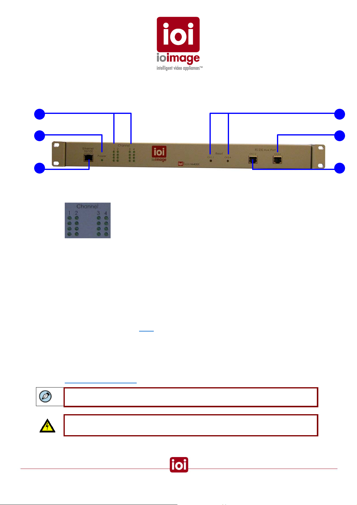
trk4000 Unit Front Panel
This section provides a short description of the trk4000 Unit front panel connections and
features.
1
2
4
5
3 6
trk4000 Front Panel
1.
LED INDICATORS
Indicator lights for each of the four channels. Each channel has a column of lights.
A Power Indicator
B Operating Light
LED POWER INDICATOR
2.
C Unassigned
D Unassigned
The light indicator for power.
3. Ethernet 10/100
Ethernet port for connecting an Ethernet cable to a local or wide area network
(LAN/WAN). There will be two IPs handled through this single connection: Channels 1
& 2 are Block 1 (first IP – Default 192.168.123.10) and Channels 3 & 4 are Block 2
(second IP – Default 192.168.123.11).
4.
Reset
Small opening that allows access to the button for hard-reset. Using a small pointed
object, such as a ballpoint pen, press to reset the ioimage Unit. Each reset button
affects two channels on the
Block as labeled.
RS232 Channels 3 & 4
5.
Serial port that supports one RS232 connection (RS232-1 setting). Primarily used for
connecting PTZ control. Note Channels 3 & 4 are on the second Block IP
configurations.
For more information on the pin-out for front panel RJ45 connections, see the
Connector Mapping Tables section (page 64).
Note: An adapter cable RJ45 to 2 x RS232 DB9 + 1 RS485 lead wires can be purchased as
a separated accessory
Warning: The RS232 standard specifies a maximum open-circuit voltage of +/-25 volts.
Exceeding this voltage can cause permanent damage to the unit.
13
Warning: The RS485 standard specifies a maximum voltage of +12 V and -7 volts.
Exceeding this voltage can cause permanent damage to the unit.
RS232/485 Channels 1 & 2
6.
Serial port supports one RS232 connection (RS232-1 setting). Primarily used for
connecting PTZ control. Note Channels 1 & 2 are on the first Block IP configurations.
For more information on the pin-out for front panel RJ45 connections, see the
Connector Mapping Tables section (page 64).
Note: An adapter cable RJ45 to RS232 DB9 can be purchased as a separated accessory
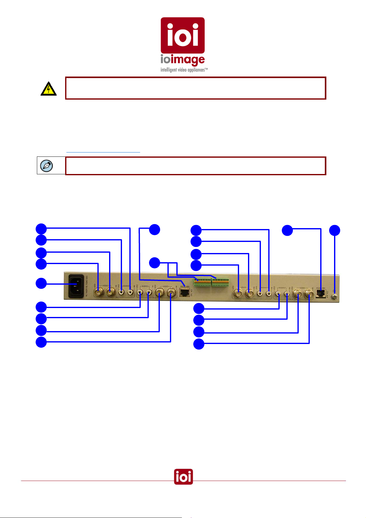
trk4000 Unit Back Panel
This section provides a short description of the trk4000 Unit back panel connections and features.
1
2
3
4
6
2
1
4
3
trk4000 Back Panel
5
7
1
2
3
4
5 8
2
1
4
3
AUDIO IN
1.
Input audio standard RCA jack (female RCA connector) for receiving sound from
external devices such as a line-level microphone (1V RMS).
2.
AUDIO OUT
T
Output audio standard RCA jack (female RCA connector) for transmitting sound to
external devices such as an amplified loudspeaker.
3.
VIDEO IN
Video input for receiving analog video signal from a standard video source, such as
from a camera or device.
14

4. VIDEO OUT
Video output for transmitting analog video signal to an analog video display, analog
video matrix, or analog video recording device. You can connect an analog monitor to
this port for viewing ioimage Unit video.
5.
RS232/485
Serial port that can be split-out for up to two connections (RS232 and RS485 support).
Primarily used for connecting PTZ control. Note Channels 1 & 2 are on the first Block
IP configurations and Channels 3 & 4 are on the second Block IP configurations.
For more information on the RJ45 pin-out for the back panel connections, see the
Connector Mapping Tables section (page 64).
Note: An adapter cable RJ45 to 2 x RS232 DB9 + 1 RS485 lead wires can be purchased as
a separated accessory
Warning: The RS232 standard specifies a maximum open-circuit voltage of +/-25 volts.
Exceeding this voltage can cause permanent damage to the unit.
Warning: The RS485 standard specifies a maximum voltage of +12 V and -7 volts.
Exceeding this voltage can cause permanent damage to the unit.
6. POWER
The power plug for connecting the IEC cord (C13/C14).
7. Alarm Inputs and Relay Outputs
Alarm Inputs
(1-8) Terminal-block-connector port for plugging in terminal block connectors. Supports
up to four input connections (a set of two wires for each) for external relay devices. The
right terminal of the two is a grounded common. For example, fire sensors, PIR, fence
sensors, etc. For more information and channel assignment, see the
Inputs section (page 38) and External Device Interfaces – ioibox Channel Assignments
(page 22).
Relay Outputs
Terminal-block-connector port for plugging in terminal block connectors. Supports
output of optoisolated signal for up to two connected external relay devices. For
example, an electrical door lock relay.
NO1, NO2 are leads for “NORMALLY OPEN” relay configurations
NC1, NC2 are leads for “NORMALLY CLOSED” relay configurations
C1, C2 are leads for COMMON wire relay configurations for either NC or NO relay. For
more information and channel assignment, see the
(page 34) and
External Device Interfaces – ioibox Channel Assignments (page 22).
Connecting Relay Outputs section
Connecting Alarm
Protective Earth Terminal
8.
ioibox must have the external protective earth terminal permanently connected to
protective earth according to local regulations and codes. For more information, see
Connecting the External Protective Earth Terminal (page 46).
15
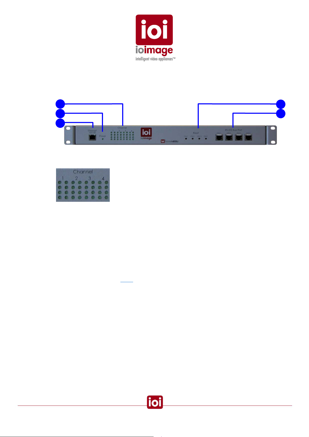
trk4000d Unit Front Panel
This section provides a short description of the trk4000d unit front panel connections and features.
1
2
3
trk4000d Front Panel
LED INDICATORS
1.
Indicator lights for each of the four channels. Each channel has a column of lights.
4
5
A Power Indicator
B Operating Light
C Unassigned
D Unassigned
LED POWER INDICATOR
2.
The light indicator for power.
3. Ethernet 10/100
Ethernet port for connecting an Ethernet cable to a local or wide area network
(LAN/WAN). There will be four IPs handled through this single connection: Channel 1
Default 192.168.123.10, Channel 2 Default 192.168.123.11, Channel 3 Default
192.168.123.12, and Channel 4 Default 192.168.123.13.
4.
RESET
Small opening that allows access to the button for hard-reset. Using a small pointed
object, such as a ballpoint pen, press to reset the ioimage Unit. Each reset button
affects two channels on the
Block as labeled.
16
5. RS232/485
Serial port that supports one RS232 connection (RS232-1 setting). Primarily used for
connecting PTZ control. Note each channel is on a separate Block IP configuration.
For more information on the pin-out for front panel RJ45 connections, see the
Connector Mapping Tables section (page 64).
Note: An adapter cable RJ45 to 2 x RS232 DB9 + 1 RS485 lead wires can be purchased as
a separated accessory
Warning: The RS232 standard specifies a maximum open-circuit voltage of +/-25 volts.
Exceeding this voltage can cause permanent damage to the unit.
Warning: The RS485 standard specifies a maximum voltage of +12 V and -7 volts.
Exceeding this voltage can cause permanent damage to the unit.
trk4000d Unit Back Panel
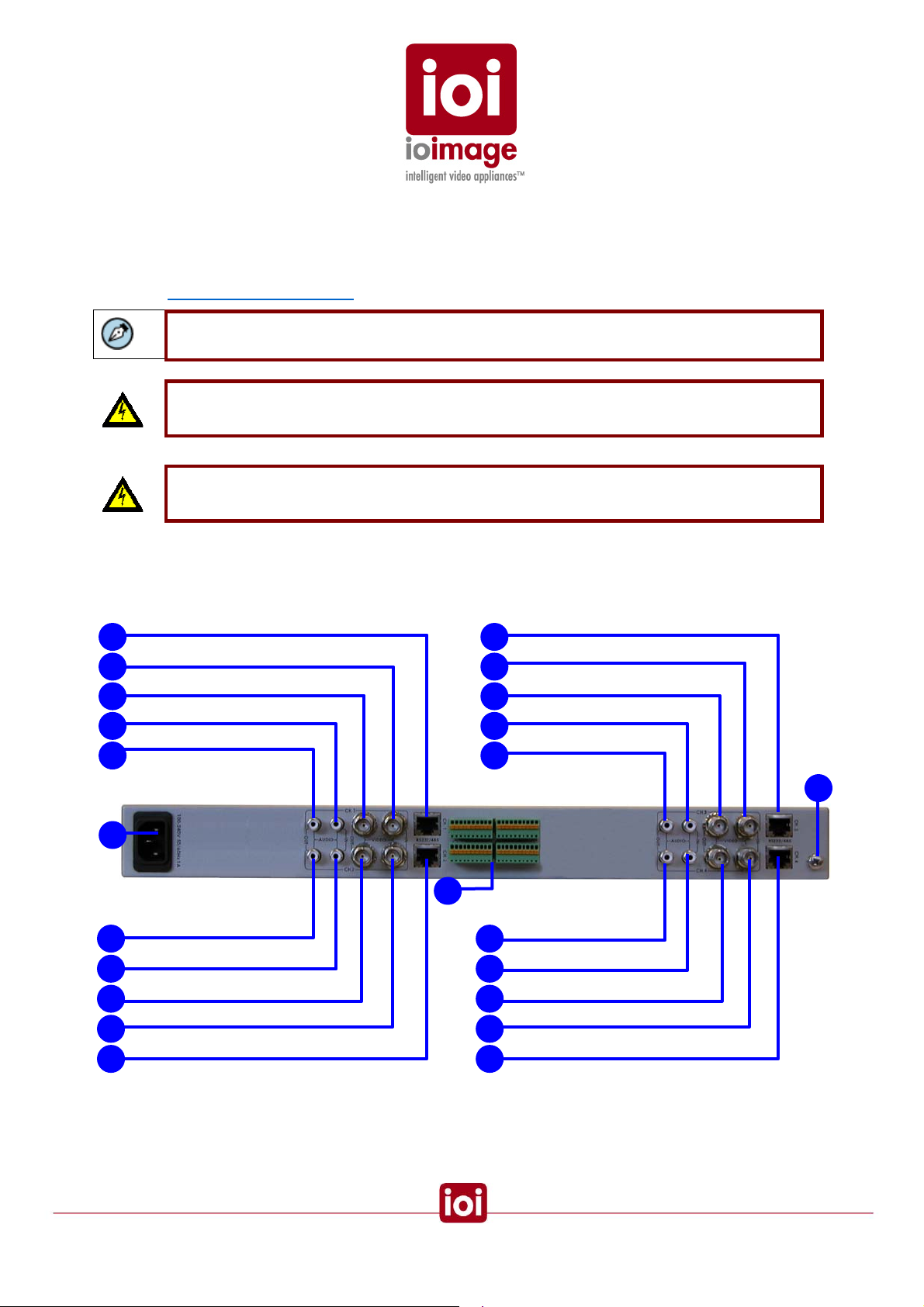
This section provides a short description of the trk4000d Unit back panel connections and features.
5 5
2
1
4
3
6
4 4
1 1
2 2
5
trk4000d Back Panel
7
3 3
5
2
1
4
3
8
VIDEO IN
1.
Video input for receiving analog video signal from a standard video source, such as
from a camera or device.
17
 Loading...