


trk100, trk100d, and trk200
HW Installation Manual
ioimage, the ioimage logo, ioimage analytics®, ioiware, ioibox, trk10, trk10d, trk100, trk100d, trk200, trk4000,
trk4000rm, trk4000d, and trk8000, ioiware command center, ioiware setup, ioibox lvm300, ioicam wdc100dn,
ioicam mmp100dn, and ioicam xptz100dn, are trademarks of ioimage Ltd. Products and trademarks
mentioned herein are for identification purposes only and may be registered trademarks of their respective
companies. Specification is subject to change without notice.
2004-2007© ioimage Ltd. All rights reserved

i
Proprietary Rights and Non-Disclosure
This Guide is delivered subject to the following restrictions and conditions:
This document contains proprietary information belonging to ioimage Ltd. This information
is supplied solely for the purpose of assisting explicitly the licensee of the ioibox units.
No part of this document contents may be used for any other purpose, disclosed to any
third party or reproduced by any means, electronic or mechanical, without the express
prior written permission of ioimage Ltd.
Disclaimer
Specifications and information in this Guide is subject to change without notice.
Copyright 2007 ioimage Ltd., all rights reserved.
Trademarks and Copyrights
This Guide and its contents are herein is owned by ioimage, Ltd., all rights reserved.
ioimage, the ioimage logo, ioimage analytics®, ioiware, ioibox, trk10, trk10d, trk100,
trk100d, trk200, trk4000, trk4000rm, trk4000d, and trk8000, ioiware command center,
ioiware setup, ioibox lvm300, wdc100dn, ioicam mmp100dn, and ioicam xptz100dn,
are trademarks of ioimage Ltd. Products and trademarks mentioned herein are for
identification purposes only and may be registered trademarks of their respective
companies. Specification is subject to change without notice.
ioimage makes no representations whatsoever about any other products or trade marks
mentioned in the manual.
2004-2007© ioimage Ltd. All rights reserved

Document Scope and Purpose
This document is intended for installation by technical users who have a basic
understanding of CCTV camera/video equipment and LAN/WAN network connections.
Installation should follow safety, standards, and electrical codes as well as the laws that
apply where the ioibox and ioicam units are being installed.
The purpose of this document is to provide instructions and installation procedures concerning how
to connect the hardware and if required, configure the ioibox unit to be connected to an existing
LAN/WAN network. After completion of the hardware installation, additional setup configurations
are required for operation of the ioibox unit. For more information on ioibox unit setup and
configuration, refer to the ioibox trk100, trk100d or trk200 HTML Edition Setup User Guide.
ii

Contents
Document Conventions....................................................................................................................1
Cautions and Warnings ....................................................................................................................1
Electrical Safety Notice ................................................................................................................3
Preventing EMI.............................................................................................................................4
Introduction.......................................................................................................................................4
Overview ......................................................................................................................................4
Items Included in the Package.....................................................................................................5
Indoor and Outdoor Installation Considerations...........................................................................5
Indoor Installation.....................................................................................................................6
Outdoor Installation..................................................................................................................6
Cablings .......................................................................................................................................7
Video Cable .............................................................................................................................7
Electric/Power Supply Cables..................................................................................................7
Hardware Description – ioibox unit.................................................................................................10
trk100/100d unit Front Panel......................................................................................................11
trk100/100d unit Back Panel ......................................................................................................12
trk200 unit Front Panel...............................................................................................................13
trk200 unit Back Panel...............................................................................................................15
Package Accessories.................................................................................................................16
Workflows.......................................................................................................................................18
Pre-Install Workflow ...................................................................................................................18
Installation Workflow ..................................................................................................................19
Post Install..................................................................................................................................19
Running a unit as Stand-Alone (Analog Only)...........................................................................20
Overview of Alarm Inputs (Dry Contacts).......................................................................................20
Overview of Relay Outputs.............................................................................................................21
Overview of RS232 and RS485 Connections ................................................................................21
PTZ Control................................................................................................................................22
Installation.......................................................................................................................................22
Connecting the ioibox unit..........................................................................................................22
Connecting to the Network.....................................................................................................23
Connecting the Video Source (camera).................................................................................24
Connecting Relay Outputs.....................................................................................................24
Connecting Alarm Inputs (Dry Contacts)...............................................................................29
Connecting PTZ Camera Controller Lines.............................................................................30
Connecting ioibox unit Video Output to an Analog Device....................................................35
Connecting the External Protective Earth Terminal...................................................................35
Connecting the Power Supply....................................................................................................35
Setting the ioibox IP ...................................................................................................................36
Setting the IP Using HTML Setup..............................................................................................37
Setting the IP Using the SiteConfigurator Application................................................................39
ioibox unit Network IP Assignment Modes – DHCP/Manual......................................................40
Resetting ioibox units.................................................................................................................40
Hard Reset Using the Reset Button on the unit.....................................................................40
Hard Reset Power Down/Power Up......................................................................................40
Camera Installation & Tips.........................................................................................................41
Appendix.........................................................................................................................................47
Connecting Leads to a Spring Clamp Terminal Block...............................................................47
Troubleshooting..........................................................................................................................48
How to Ping a ioibox unit from a Workstation............................................................................51
iii

Connector Mapping Tables........................................................................................................52
Specifications.............................................................................................................................53
Who to Contact...........................................................................................................................55
List of Figures
trk100/d Front Panel.......................................................................................................................11
trk200 Front Panel..........................................................................................................................13
trk200 Back Panel...........................................................................................................................15
Compact ioibox unit Two-Part Power Supply.................................................................................16
Relay Output Connection ...............................................................................................................25
Continuous Signal until Reset........................................................................................................27
Continuous Signal during Event.....................................................................................................27
Pulsing Signal until Reset...............................................................................................................28
Intermittent Signal during Event .....................................................................................................28
Alarm Input Connection..................................................................................................................29
PTZ control lines connected with the adapter cable RS485 lead-wires.........................................31
Connecting PTZ Camera Control Lines to RS232 DB9 on the ioibox unit.....................................33
Connecting a Wire to a Terminal Block..........................................................................................47
RS232/485 Pin Diagram.................................................................................................................52
iv
Document Conventions
The following document conventions are used throughout this manual:
A
WARNING is a precautionary message that indicates a procedure or condition where
there are potential hazards of personal injury or death
A
CAUTION is a precautionary message that indicates a procedure or condition where there
are potential hazards of permanent damage to the equipment and or loss of data.
A
Note is useful information to prevent problems, help with successful installation, or to
provide additional understanding of the products and installation.
A
Tip is information and best practices that are useful or provide some benefit for installation
and use of ioimage products.
Cautions and Warnings
This section contains information that indicates a procedure or condition where there are potential
hazards. These may be hazards associated with a task or procedure a user is carrying out or about
to carry out.
WARNINGS and CAUTIONS are distributed throughout this document, whenever applicable, to
alert the user of potentially hazardous situations.
Although the ioibox unit is designed and manufactured in compliance with all applicable safety
standards, certain hazards are present during the installation of this equipment.
Definitions:
A WARNING is a precautionary message that indicates a procedure or condition where
there are potential hazards of personal injury or death.
A CAUTION is a precautionary message that indicates a procedure or condition where there
are potential hazards of permanent damage to the equipment and or loss of data.
Failure in part or in whole of the installer, owner, or user in any way to follow the prescribed
procedures or to heed WARNINGS and CAUTIONS shall absolve ioimage Inc. and its agents from
any resulting liability.
SAVE THESE INSTRUCTIONS: Retain all safety and operating instructions for future use.
To avoid injury or possible damage to hardware components, read and follow all instructions
marked on the product and in the documentation before you install or connect the ioibox unit to a
power source.
1
Warning:
The ioibox unit cover is an essential part of the product. Do not open or remove this cover.
Never operate the ioibox unit without the cover in place. Operating the ioibox unit without the
cover in place poses a risk of fire and shock hazards
.
Warning:
To prevent injury or damage to the ioibox unit, do not insert any objects into the vents of the
ioibox unit
.
Warning:
The ioibox unit uses a three-wire power cord to make sure that the product is properly
grounded when in use. The plug on this cord will only fit into a grounding-type outlet. This is
a safety feature. If the intended power outlet does not support three prongs, one of which is
a ground, contact an electrician to install the appropriate outlet. NEVER remove or otherwise
attempt to defeat the ground pin of the power cord. Do not operate the ioibox unit in the
absence of a suitably installed ground conductor
.
Warning:
If you use an extension cord with this system, make sure that the total ampere rating on the
products plugged into the extension cord does not exceed the extension cord ampere rating
.
Warning:
Only qualified trained personnel should service and repair this equipment.
Warning:
Assure the connected electrical power source uses a circuit breaker or fuse no larger than
120 VAC, 15A U.S. and 240 VAC, 10A international are used on the phase conductors (all
current-carrying conductors).
Warning:
Read the installation instructions before you connect the ioibox unit to a power source.
Caution:
To avoid damage from overheating or unit failure, do not block the side vents of the ioibox
units and assure, there is sufficient temperature regulation to support the ioibox unit
requirements (cooling/heating). Ambient operating temperature should be kept in the range
0°c to 50°c.
2

Electrical Safety Notice
In the following situations, the electric power should be turned off and appropriate repairs,
replacements or remedies should be taken.
• The power cord or plug is damaged, frayed or shows heavy wear
• The ioibox unit has been physically crushed or deformed
• The ioibox unit has been exposed to water
• The ioibox unit has been exposed to fire, intense heat or heavy smoke
• Electrical connections of the ioibox unit become abnormally hot or smoke
• The ioibox unit has been dropped, damaged or shows signs of loose internal parts.
• The ioibox unit power light fails to illuminate or the ioibox unit does not operate
properly
• The ioibox unit shows signs of damage from exposure to fumes or vapors
3

Preventing EMI
When wires run for a significant distance in an electromagnetic field, Electromagnetic Interference
(EMI) can occur
.
Note:
• Poor quality or worn wiring can result in Radio Frequency Interference (RFI)
• Strong EMI, (e.g. lightning or radio transmitters) can destroy the ioibox units, and can
pose an electrical hazard by conducting power through lines and into the system
.
To remedy EMI, consult RFI experts.
Introduction
The installation of the ioibox unit hardware is the first phase of making a ioibox unit operational in a
security plan. The goal of hardware installation is to physically place the unit, connect it to other
devices in the system and to establish network connectivity in preparation for phase two of the
installation process which is the camera setup and configuration of the ioibox.
When finished with the Compact ioibox unit hardware installation, you will need to refer to the ioibox
HTML Edition Setup User Guide to complete the second phase of installation, which is the setup
and configuration of the ioibox units.
Overview
There are several requirements that should be properly addressed prior to installation. The
following specifications are requirements for proper installation and operation of ioibox units:
• Ambient Environment Conditions: (indoors or outdoors) Keep the ioibox unit in a
clean and dry environment. Operating temperature should be maintained within 0°c to
50°c. Operating humidity 5% to 95% (non-condensing). The ioibox unit should be kept
dry and free from water condensation. To prevent overheating, avoid positioning the
ioibox unit near heaters or heating system outputs and avoid exposure to direct
sunlight. Keep the ioibox unit free from dust, dirt, smoke, and exposure to EMI.
• Accessibility: The location used should allow easy access to unit connections and
cables. Leave at least 33 cm (1 foot) behind the unit to allow for easy cable access.
• Safety: Cables and electrical cords should be routed in a manner that prevents safety
hazards, such as from tripping, wire fraying, overheating, etc. Assure that nothing
rests on the ioibox cables or power cords
.
• Ample Air Circulation: Leave enough space around the ioibox unit to allow free air
circulation.
• Proximal Location: units should be placed in locations that are optimal for the type
of video cabling used between the unit and the cameras and external devices. Using
a cable longer than the manufacturer’s specifications for optimal video signal may
result in degradation of color and video parameters.
• Physical Security
ioibox units provide threat detection for physical security systems. In order to ensure
ioibox units cannot be disabled or tampered with, the systems should be installed with
security measures regarding physical access by trusted and un-trusted parties.
4
• Network Security
ioibox units transmit over IP to security personnel for video surveillance. Proper
network security measures should be in place to assure networks remain operating
and free from malicious interference. ioibox units are intended for installation on the
backbone of a trusted network.
• Electrostatic Safeguards
ioibox units as well as other equipment connected to it (relay outputs, alarm inputs,
racks, carpeting, etc) shall be properly grounded to prevent electrostatic discharge.
Items Included in the Package
This section describes the items that are included in the ioibox unit package.
The trk100, trk10d and trk200 unit package contains the following:
QTY Description
1 The ioibox unit (trk100, trk100d or trk200)
1 Power Supply with IEC power cord (C13)
2 Terminal-block spring-clamp-connectors for Alarm Input and Relay Output wire
termination
1 Documentation and utilities CD
1 Quick reference guide
Indoor and Outdoor Installation Considerations
The following sections provide insight and key information that should be considered when
installing the Compact ioibox units:
• Indoor Installation (page 6)
• Outdoor Installation (page 6)
Caution
To avoid damage from overheating or unit failure, assure, there is sufficient temperature
regulation to support the ioibox unit requirements (cooling/heating). Ambient temperature
should be kept in the range -20°c to 50°c
5

Indoor Installation
The following are additional consideration for an indoor installation.
• There must be a fuse or breaker at the starting point of the electrical wiring
infrastructure.
• For indoor installations, such as industrial installation, the ioibox units must be
protected from elements, such as damaging fumes, metallic dust, extreme
temperatures, soot, moisture, over-spray, etc.
.• ioibox units should not be placed near or on radiators and heat sources
Outdoor Installation
The following are additional consideration for an outdoor installation.
• For any outside wiring installation, always use weatherproof equipment, su ch as
boxes, receptacles, connectors, etc.
• For electrical wiring use the properly rated sheathed cables for conditions whi ch the
cable will be exposed to (e.g. moister, heat, UV, and physical requirements, etc)
• ioibox units must be protected from weather conditions. Units should be installed
within secure weatherproof storage, such as an outdoor communication cabinets,
junction boxes, or system cabinets.
• Plan ahead to determine where to install weatherproof outlet boxes and ioibox unit
storage. Whenever possible ground weatherproof boxes to an outdoor ground.
• Outdoor boxes should provide some form of a security locking mechanism.
• Look for an enclosure/casing suited for protecting the ioibox as needed for your
installation environment. It is recommended that a rating of IP65 / NEMA 4 or greater
be used. The following table provides National Electrical Manufacturers Association
(NEMA) and Institute of Petroleum ratings. These are US and European ratings that
indicate an enclosures ability to withstand certain environmental conditions:
Rating Description
IP54 / NEMA 2 Protected against splashing water and the ingress of most dust
IP65 / NEMA 4 Completely protected against the ingress of dust and against water jets
NEMA 4X Same as NEMA 4 with the added benefit of being corrosion proof
IP67 / NEMA 6 Can be immersed in water under defined conditions and completely protected
against the ingress of dust
6
Cablings
Cabling should be routed for the shortest path and minimizing impedance. Cabling routes should be
planned for the fewest bends. Avoid unnecessary connections and use only approved conne ctors in
locations that provide accessibility.
The following sections discuss different considerations for the different cabling types:
Video Cable (page 7)
Electric/Power Supply Cables (page 7)
Video Cable
Use the appropriate connectors for indoor an outdoor cabling. Cables should be maintained at
scheduled intervals, connections should be secured, and worn or damaged cables should be
replaced to assure optimally low impedance.
Recommended Cable Specifications:
• 75 coaxial cable impedance
Note
Using a cable longer than the manufacturer’s specifications for optimal video signal may
result in degradation of color and video parameters.
Warning
To avoid damage to the system and system interference, a certified electrician must assure
that the ground voltage (ground loops and foreign stray voltage) is comparable among all
connected system components (ground isolation transformer may be requi red to solve
ground loop problems). This relates to all grounded devices as well as the shield of video
cables and equipment racks.
Electric/Power Supply Cables
The following should be considered for electrical wiring and cables:
Warning
To prevent bodily injury or possible death, shut off the electrical current at the main switch
before tying-in wiring.
7

Warning:
The ioibox unit uses a three-wire power cord to make sure that the product is properly
grounded when in use. The plug on this cord will only fit into a grounding-type outlet. This is
a safety feature. If the intended power outlet does not support three prongs, one of which is
a ground, contact an electrician to install the appropriate outlet. NEVER remove or otherwise
attempt to defeat the ground pin of the power cord. Do not operate the ioibox unit in the
absence of a suitably installed ground conductor
.
• Check the local codes regarding indoor or outdoor wiring. Electrical wirin g should be
installed in accordance with local codes and safety requirements.
• ioimage units must have the external protective earth terminal permanently connected
to protective earth according to local regulations and codes. For more information,
see
Connecting the External Protective Earth Terminal (page 35).
• The protective grounding conductor should be aluminum. The lug of the protective
grounding conductor should be aluminum; washers and screws should be hi Cr
stainless steel, or 12% Cr stainless steel, or Cr on, Ni on steel, tin, or steel.
• External protective earth stud must be permanently connected to the protective earth.
• US + Canada
INSTALLATION CODES
This device must be installed according top the latest version of the country national
electric codes. For North America, equipment must be installed in accordance to the
applicable requirements in the US National Electrical Code and the Cana dian
Electrical Code.
• North America power connection: “select a power supply cord that is UL Listed and
CSA Certified: 3 – conductor, 18 AWG, terminated in a molded on plug cap rated 125
V, 15 A, with a minimum length of 1.5m (six feet) but no longer than 4.5m.”
• Electrical infrastructure and wiring should be installed by a licensed Electrician.
• Electrical cabling must contain a grounding conductor. All electrical components and
devices must be grounded for complete safety, especially for outdoor installations. To
help prevent electric shock, the power supply should be connected to properly
grounded electrical outlets. Electrical cords with three-prong plugs to help ensure
grounding. Do not use adapter plugs or remove the grounding prong from a cable.
• Many local codes now require outdoor electrical circuits to be protected with GFIs,
(Ground Fault Interrupters). Check your local code. GFIs are required in most areas
for outdoor circuits. Follow the manufacturer's instructions for the installation of the
type of GFI you decide to use.
• Ensure that power cables are rated for the ioibox units voltage and current
requirements. The voltage and current rating of the cable should be greater than the
ioibox unit ratings defined in this guide and marked on the product.
• To help protect the ioibox units and connected system components from sudden,
transient increases and decreases in electrical power, use a surge suppressor, line
conditioner, or uninterruptible power supply (UPS).
8
• For underground wiring, always bury any underground cable at least 18" deep, but
24" is preferable. Cables buried at least 24" deep are less likely to be bothered or dug
up.
• Always use at least type UF sheathed cables for installations requiring underground
electrical wiring.
• There must be a fuse or breaker at the starting point of the electrical wiring
installation.
Electrical Power Supply
The ioibox unit Power Supply, included in the package, is designed specifically for the power
requirements of the Compact ioibox units.
Caution
Always use the properly rated external power supply.
If you use a replacement power supply, note that several competing standards exist and in some
cases incompatible plugs will fit or can be made to fit, thus permanently damaging equipment and
the ioibox unit. Beware of improper voltage, reversed polarity, exceeded current ratings, connector
damage caused by incompatible connectors.
The following are power supply specifications for the trk100, trk100d, and trk200:
• Power Supply Input: 110-240V ~ 1.0A 47-63Hz
• Power Supply Output: 12V 2.5Amax 25Wmax
• Polarity:
Note: The DSP embedded in the ioibox unit uses a flash memory; therefore configuration
settings are maintained even when the unit receives no power.
9

Hardware Description – ioibox unit
ioibox unit converts analog cameras into streaming MPEG-4 over IP cameras and transforms
inanimate cameras into smart proficient cameras that identify threats, track intruders, and take
action automatically. The ioibox unit contains an embedded DSP platform, (no PC based
processing) that provides intelligent-video analysis and tracking software for running algorith ms and
real-time audio and video MPEG-4 encoding and streaming.
The DSP must be configured through the IP connection of the ioibox unit in order for the unit to
operate ioimage module features. The built-in modules include:
• Intrusion Detection for detecting intruder scenarios
• PTZ Tracking for transforming pan/tilt/zoom cameras into self-directed intruder-
tracking systems
• Unattended Baggage Unattended Threat Detection for detecting left-behind
baggage scenarios
• Object Removal Object Removal Detection for detecting if an object has been
removed
• Stopped Vehicle No Parking/Stopped vehicle tracking for detecting if a vehicle is in
violation of parking and standing rules
10
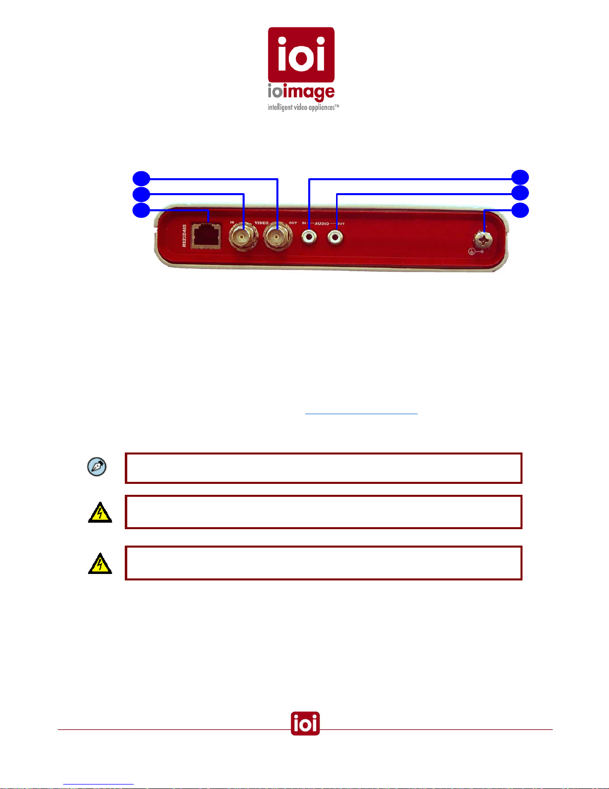
trk100/100d unit Front Panel
This section provides a short description of the trk100 unit’s front panel connections and
features.
4
1
5
2
6 3
trk100/d Front Panel
1.
VIDEO OUT
Video output for sending analog video signal to an analog video display, analog
video matrix, or analog video recording device.
2.
VIDEO IN
Video input for receiving analog video signal from a video source, such as a
camera.
3.
RS232/485
Serial port that can be split-out for two up to two connections (RS232 and
RS485 support). Primarily used for connecting PTZ control. For more
information on the pin-out, see the
Connector Mapping Tables section (page
52). Can be utilized from custom programs that use the ioimage-API
(application program interface). For more information, refer to the ioimage-API
User Guide.
Note: An adapter cable RJ45 to 2 x RS232 DB9 + 1 RS485 lead wires can be purchased as
a separated accessory
Warning: The RS232 standard specifies a maximum open-circuit voltage of +/-25 volts.
Exceeding this voltage can cause permanent damage to the unit.
Warning: The RS485 standard specifies a maximum voltage of +12 V and -7 volts.
Exceeding this voltage can cause permanent damage to the unit.
4.
AUDIO IN
Input audio standard RCA jack (female RCA connector) for receiving sound
from external devices such as a microphone.
5.
AUDIO OUT
Output audio standard RCA jack (female RCA connector) for sending sound to
external devices such as a loudspeaker.
T
11
6. Protective Earth Terminal
ioibox must have the external protective earth terminal permanently connected
to protective earth according to local regulations and codes. For more
information, see
Connecting the External Protective Earth Terminal (page 35).
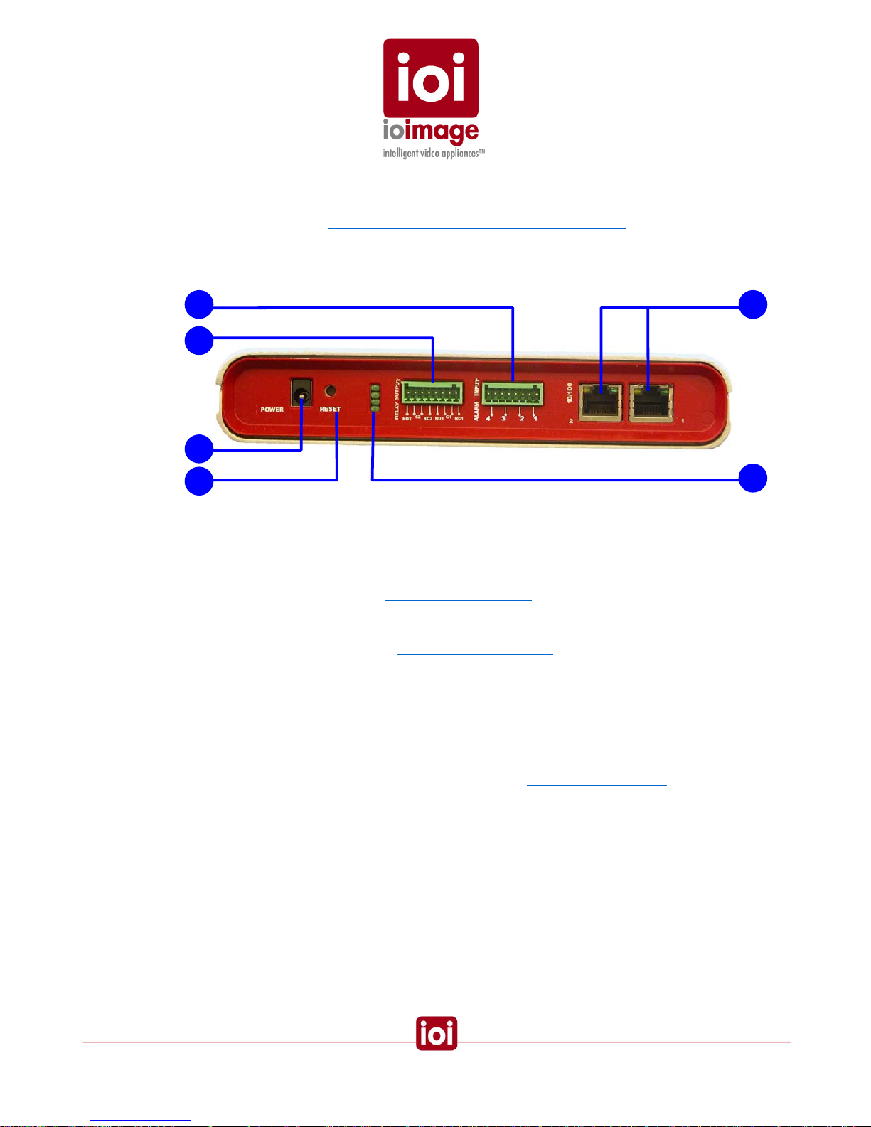
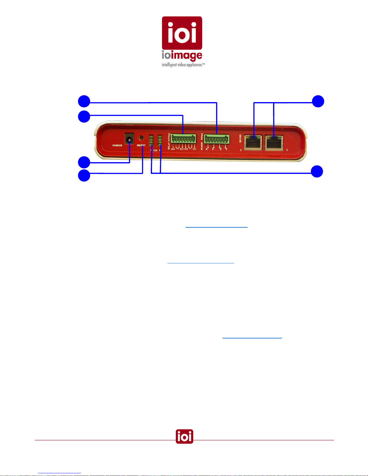
trk100/100d unit Back Panel
The rear panel of the trk100 appears as follows:
3
6
4
5 1
2
trk100 Back Panel
1.
ALARM INPUT
(1, 2, 3, 4) Terminal-block-connector port for plugging in the terminal block
connector. Supports up to four input connections (a set of two wires for each)
for external devices For example, fire sensors, PIR, fence sensors, etc. For
more information, see the
T
Connecting Alarm Inputs section (page 29).
2.
RELAY OUTPUT
Terminal-block-connector port for plugging in the terminal block connecto r as
shown in the diagram in the
Connecting Relay Outputs section (page 24).
Supports output of optoisolated signal for up to two connected external
devices. For example, an electrical door lock relay.
NO1, NO2 are leads for “NORMALLY OPEN” configurations
NC1, NC2 are leads for “NORMALLY CLOSED” configurations
C1, C2 are leads for COMMON wire configurations for either NC or NO.
3.
POWER
The power supply electrical jack for plugging in the power supply that came
with the ioibox unit. For more information, see the
Electrical Power Supply
section (page 9).
4. RESET
Small opening that allows access to the button for hard-reset. Using a small
pointed object, such as a ballpoint pen, press to reset the internal ioibox unit
software on the DSP.
12
5. Ethernet 10/100
(1) Primary Ethernet port for connecting an Ethernet cable to a local or wide
area network (LAN/WAN).
(2) Secondary Ethernet port for connecting an Ethernet cable, such as for daisy
chain connection between multiple ioibox units.
6.
LED INDICATORS
1 Unassigned
2 Unassigned
3 Operating Light
4 Power Indicator
1
2
3
4
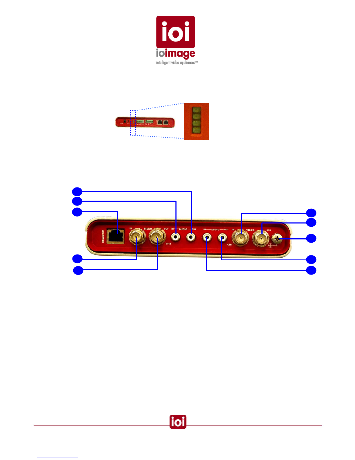
trk200 unit Front Panel
This section provides a short description of the trk200 unit front panel connections and
features.
1
2
3
4
5
trk200 Front Panel
1. AUDIO OUT
Output audio standard RCA jack (female RCA connector) for transmitting
sound to external devices such as a loudspeaker.
2. AUDIO IN
Input audio standard RCA jack (female RCA connector) for receiving sound
from external devices such as a microphone.
4
5
1
6
2
13

3. RS232/485
Serial port that can be split-out for two up to two connections (RS232 and
RS485 support). Primarily used for connecting PTZ control. For more
information on the pin-out, see the
Connector Mapping Tables section (page
52). Can be utilized from custom programs that use the ioimage-API
(application program interface). For more information, refer to the ioimage-API
User Guide.
Note: An adapter cable RJ45 to 2 x RS232 DB9 + 1 RS485 lead wires can be purchased as
a separated accessory
Warning: The RS232 standard specifies a maximum open-circuit voltage of +/-25 volts.
Exceeding this voltage can cause permanent damage to the unit.
Warning: The RS485 standard specifies a maximum voltage of +12 V and -7 volts.
Exceeding this voltage can cause permanent damage to the unit.
4. VIDEO IN
Video input for receiving analog video signal, such as from a camera or device.
5. VIDEO OUT
Video output for transmitting analog video signal to an analog video display,
analog video matrix, or analog video recording device.
6. Protective Earth Terminal
ioibox must have the external protective earth terminal permanently connected
to protective earth according to local regulations and codes. For more
information, see
Connecting the External Protective Earth Terminal (page 35).
14
trk200 unit Back Panel
The rear panel of the trk200 appears as follows:
4
6
3
5
2
1
trk200 Back Panel
1. ALARM INPUT
Terminal-block-connector port for plugging in the terminal block connector.
Supports up to four input connections (a set of two wires for each) for external
devices For example, fire sensors, PIR, fence sensors, etc. For more
information, see the diagram in the
Connecting Alarm Inputs section (page 29).
Alarm Input 1 & 2 are configured on channel 1 and Alarm Input 3 & 4 are
configured on channel 2.
2. RELAY OUTPUT
Terminal-block-connector port for plugging in the terminal block connecto r as
shown in the diagram in the
Connecting Relay Outputs section (page 24).
Supports output of optoisolated signal for up to two connected external
devices. For example, an electrical door lock relay.
NO1 (channel 1), NO2 (channel 2) are leads for “NORMALLY OPEN”
configurations
NC1 (channel 1), NC2 (channel 2) are leads for “NORMALLY CLOSED”
configurations
C1 (channel 1), C2 (channel 1) are leads for COMMON wire configurations for
either NC or NO.
3. POWER
The power supply electrical jack for plugging in the power supply that came
with the ioibox unit. For more information, see the
Electrical Power Supply
section (page 9).
4. RESET
Small opening that allows access to the button for hard-reset. Using a small
pointed object, such as a ballpoint pen, press to reset the internal ioibox unit
software on the DSP.
15

5. Ethernet 10/100
(1) Primary Ethernet port for connecting an Ethernet cable to a local or wide
area network (LAN/WAN).
(2) Secondary Ethernet port for connecting an Ethernet cable, such as for daisy
chain connection between multiple ioibox units.
6. LED INDICATORS
Left column is for channel 1
Right column is for channel 2
1 Unassigned 2 Unassigned
3 Operating Light 4 Power Indicator
1 2
1
2
3
4
Package Accessories
• Power supply includes two parts the transformer unit and an IEC cord (C13/C14).
Compact ioibox unit Two-Part Power Supply
Specifications:
Power Supply Input: 110-240V ~ 1.0A 47-63Hz
Power Supply Output: 12V
0.6A
Polarity:
• Terminal-block spring-clamp-connectors for Relay Output and Alarm Input wire
termination.
16

• Adapter Cable (Optional)
An adapter cable RJ45 to 2 x RS232 DB9 + 1 RS485 lead wires can be purchased as
a separated accessory
• Installation CD
CD includes Documentation
17

Workflows
The following are general workflows for installation as well as pre and post installation steps. The
workflows are only guidelines; individual installations may require variations based on the needs of
the site.
This section contains the following sections:
• Pre-Install Workflow (page 18)
• Installation Workflow (page 19)
• Post Install Workflow (page 19)
Pre-Install Workflow
1. Pre-install for Install video cameras.
2. Determine ioibox unit storage. Install boxes and associate equipment if
needed.
3. Install electrical infrastructure (conduit, electrical wiring, boxes, breakers,
grounded outlets, switches, UPS, surge protector, grounds, etc.).
4. Establish or Install LAN/WAN network access for ioibox unit location (network
wiring, ports, wireless, WAP (Wireless Access Point), etc.).
5. Install wiring between interfaces to external devices (Relay Outputs, Dry
contact Alarm Inputs) and the ioibox location.
6. Install video monitors and the wiring to connect to the ioibox unit location.
7. Install wiring between PTZ controller leads and the ioibox unit location.
8. Connect the workstation computer to the network.
Tip: The unit is delivered from manufacture with a pre-configured IP address. Change the
pre-configured IP address to match your network IP mapping before connecting the unit to
the network.
Tip: It is possible to access the HTML setup menu in the unit by connecting from a laptop/PC
directly to the unit using a network cable and typing the IP address on an IE web browser
Pre-install for stand-alone using only the analog video output
1. Install video cameras.
2. Determine ioibox unit storage. Install boxes and associate equipment if
needed.
3. Install electrical infrastructure (electrical wiring, boxes, breakers, grounded
outlets, switches, UPS, surge protector, grounds, etc.).
18

4. Install wiring between dry contacts (Relay Outputs and Alarm Inputs) and the
ioibox unit location.
5. Install video monitors and the wiring to connect to the ioibox unit location.
6. Install and connect the wiring between PTZ controller leads and the ioibox unit
location.
7. Install wiring (RS232) between the Video Matrix and the ioibox unit location.
8. Turn on the cameras, matrix switcher, monitors as well as any external devices
(connected to the units through Relay Outputs and Alarm Inputs).
Installation Workflow
1. Establish Network IP
Check if the ioibox units default settings on each
Block (IPs, DHCP, Subnet
Mask, Gateway) can be used on the IP network. If not, change the settings for
each Block via the HTML setup or SiteConfigurator application. If necessary,
configure the LAN/WAN to support the ioibox unit Block IPs.
2. Place the ioibox unit.
Select a location to store the ioibox unit installing necessary cooling, shelter
and ventilation to maintain proper ambient environment.
3. Connect the ioibox unit to input and output wires.
4. Connect the electric to the ioibox unit.
5. Write down the ioibox IP addresses. Note which cameras and dry contacts
(Relay Outputs and Alarm Inputs) are connected with descriptions. Note the
camera model as well as which cameras are PTZ and which are stationary.
6. If you choose to make changes to the ioibox unit network settings, use the
ioibox HTML Edition Setup (IP, submask and gateway).
Note
In order for the ioiboxes to detect and track, the channel must be armed with an active rule
defined in the setup. For more information, refer to the HTML Edition Setup User Guide.
Post Install
The following general workflow outlines the tasks that will need to be done after the install of
ioiboxes. These post install procedures are mentioned in this document but are covered in greater
detail in the ioibox HTML Edition Setup User Guide. Please refer to these guides for more detail.
1. Configure the compact unit using its built in HTML setup application. Configure
the unit, and camera including Relay Outputs, Alarm Inputs, etc. For more
information, refer to the ioibox HTML Edition Setup User Guide.
2. Connect monitoring computers with a supported web browser or supporte d
RTSP device. If using analog only connect to the analog monitors.
19

Running a unit as Stand-Alone (Analog Only)
Running a ioibox unit in analog stand-alone offers tracking and threat detection without the need for
a network. If the IP network infrastructure will not be used and the existing analog infrastructure will
continue to be maintained, accessibility to the ioibox units for additional configurations should be
considered, especially if the units are installed in hard to reach locations.
In situations where there is no network infrastructure permanently connected to the ioibox units, the
ability to make adjustments and configurations requires the ioibox unit be reconnected to a
computer (network) for configuration.
Use of a laptop may offer some mobility, however units and cameras may be installed hard to reach
locations or pose some risk in accessing them. For these situations it may be useful to wire
accessible extensions to provide optimal configuration of these units.
The ability to use programmed incident responses in an analog-only configurations can provide
considerable benefits, such as a lockdown on threat detection. With an analog-only system, the
ability to change or command ioibox units and their connected relay contacts will not be available in
analog only monitors.
Consideration and care needs to be given to how the security officers will reset, command, and
override incident responses. For example, if the system detects someone walking in a detection
zone and automatically executes a lockdown, security officers should have a bypass to the
lockdown.
Overview of Alarm Inputs (Dry Contacts)
Alarm Inputs of the ioibox units allow interaction among the ioibox units, cameras, and signals sent
from external devices.
The units can receive input signals (dry contact close/open) from external devices. For example,
fire alarms, PIR, magnetic sensors, fence sensors, break glass stations, control valve sensors,
mercury switches, etc and use them for triggering automatic actions.
CAUTION
To avoid damage to the system and system interference, a certified electrician must assure
that the ground voltage (ground loops) is comparable among all connected system
components.
CAUTION
Assure the common ground terminal connection for alarm inputs is connected in the right
terminal connector socket of an Alarm Input pair.
Specification: Dry Contacts (max. 24VDC 100mA) IN
For more information on Alarm Inputs, see the
Connecting Alarm Inputs section (page 29).
20

Overview of Relay Outputs
An external device can be connected to the Relay Output terminal block of the unit. In response to
events such as alarm inputs, intruder alarms, poor visibility, etc. signals can be sent to operate
external devices.
For more information on Relay Outputs, see the
Connecting Relay Outputs section (page 24).
CAUTION
To avoid damage to the system and system interference, a certified electrician must assure
that the ground voltage is comparable (ground loops) among all connected system
components.
Caution
Consideration and care needs to be given regarding how the security officers will reset,
command, and override incident responses. For example, if the system detects someone
walking in a detection zone and automatically executes a lockdown, security officers may
need a bypass for the lockdown.
Overview of RS232 and RS485 Connections
The RS262/485 connections made to the ioibox unit are made through the adapter cable. Dual
connections split from one port to provide the ability to connect two devices, such as a PTZ camera.
Warning: The RS232 standard specifies a maximum open-circuit voltage of +/-25 volts.
Exceeding this voltage can cause permanent damage to the unit.
Warning: The RS485 standard specifies a maximum voltage of +12 V and -7 volts.
Exceeding this voltage can cause permanent damage to the unit.
There are two possible combinations of connections converted from a single RJ45 port as follows
using the adapter cable:
• Two RS232 connections
• One RS485 connection and one RS232 connection
21

PTZ Control
The ioibox units support connection of control lines to the RS232/485 port (controller wire leads) for
a PTZ camera. Once connected the PTZ camera can be controlled from remote from within the
HTML Live View/Setup and Command Center software using the built-in PTZ Remote Control
Panel. For more information on connecting the PTZ camera control lines, see the
Connecting PTZ
Cameras section (page 30).
Installation
Installation of ioibox units contains several steps. These steps are described in the following
sections:
• Connecting the ioibox unit (page 22)
• Connecting the Power Supply (page 35)
• Setting the ioibox unit IPs (page 36)
• Resetting ioibox units (page 40)
• ioibox unit Network IP Assignment Modes – DHCP/Manual (page 40)
Connecting the ioibox unit
This section contains explanations and procedures for connecting the ioibox units. Note that the
power connection is recommended to be the last step of the first phase of hardware installation.
This section contains the following:
• Connecting to the Network (page 23)
• Connecting the Video Source (page 24)
• Connecting Relay Outputs (page 24)
• Connecting Alarm Inputs (page 29)
• Connecting PTZ Cameras (page 30)
• Connecting ioibox unit Video Output to a Analog Device (page 35)
• Connecting the Power Supply (page 35)
22

Connecting to the Network
Before connecting the ioibox to the network assure that the LAN/WAN supports the ioibox IP and
will allow communication with remote workstations where the web browser or monitoring application
is installed.
By default ioiboxes are shipped with a factory set IP and MAC addresses labeled on the ioibox
package and the automatic network IP configuration mode is disabled for DHCP connectivity.
If your network uses a firewall, you must configure the firewall to support communication among the
units, applications, and Internet Browser. The following communication needs to be supported
between units:
• HTTP
o Used for: Commands, Requests, Replies and notifications
o IP port: 80
• NTP
o Used for: Time synchronization with a network time server using SNTP
o IP port: 123
• RTSP
o Used for: RTP session setup
o IP port:554
• RTP
o Used for: Multimedia streaming
o IP port: 2000 to 65535
• Multicast UDP
o Used for: Units self publishi ng
o IP address: 224.9.9.9
o IP port: 57346
:
To Connect a Compact ioibox unit to the Network
• Connect one end of the Ethernet cable to the network port and the end to
the Ethernet 10/100 port labeled “1” on the front of the ioibox unit.
Related Links
How to Ping a ioibox unit from a Workstation (page 51)
23

Connecting the Video Source (camera)
The ioibox unit accepts video input from analog cameras and devices.
Video connections should use 75
cable and are not recommended to be greater than 30 meters
(98 feet). For more information on video cable specifications, see the
Video Cable section (page 7).
To Connect a Video Source to the ioibox unit
1. Securely connect the video cable to the output of the camera or device.
2. Connect the other cable end to ioibox unit VIDEO IN connection on the back of
the ioibox unit.
This cable should be providing live video signal before powering up the ioibox
unit.
Tip
For trk200 units, be certain to note which camera is connected to each channel of a Block
(pair of channels that has an individual IP). This information will help during configuration in
the ioibox Setup.
Note
For PTZ cameras, you will need to connect the control lines of the PTZ camera in order to
use the pan, tilt, and zoom operability. For more information, see the
Connecting PTZ
Camera Control Lines (Remote Control) procedure (page 30).
Connecting Relay Outputs
For incident responses and device automatic commanding through the ioibox, you ca n connect
external devices, such as door locks, lights, etc. to the Normally Open or Normally Closed relay
outputs of the unit.
Relay outputs connected to the ioibox units can be assigned as automatic incident responses to
events and alerts received on the ioibox units. These are events such as intruder alarms, poor
signal, low visibility, etc. For example, an intruder is detected in a courtyard, as an automatic
incident response, exit doors are locked and security shutters are closed.
For more information on incident responses and relay outputs, refer to the ioibox HTML Edition
Setup User Guide.
Caution
To prevent damage to the ioibox units, do not exceed the voltage and current ratings for
Relay terminals.
24

CAUTION
To avoid damage to the system and system interference, a certified electrician must assure
that the ground voltage (ground loops) is comparable among all connected system
components.
Relay Output Specifications
• Maximum current 1A @ 24VDC
• Maximum current 0.5A @ 125VAC
Relay Output Connection
If the Relay Output wires are in a shielded, cable, connect the shielded wire to any of the common
terminals.
25
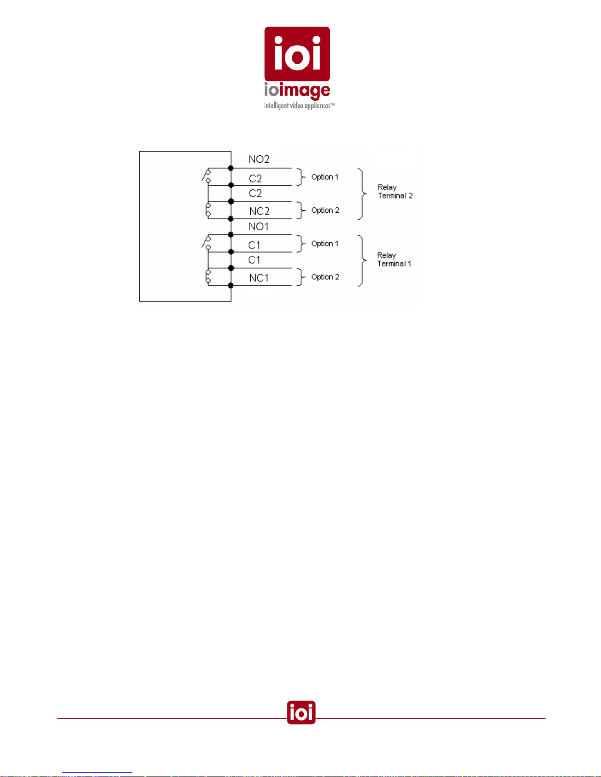
Relay Contacts Schematic
• NC1 NC2
This is the terminal for connecting the wire that leads to the external device that is on
a circuit that is “Normally Closed”.
• NO1 NO2
This is the terminal for connecting the wire that leads to the external device that is on
a circuit that is “Normally Open”.
• C1, C2 (COMMON)
This is the second of the pair of connections made for an external device. This
terminal is for connecting the wire that leads to COMMON terminal of the external
device when connecting either a Normally Open or Normally Closed device.
A Relay Output terminal has two options for connecting a device:
• Option 1 is for a Normally Open configuration.
• Option 2 is for a Normally Closed configuration.
Output supports optoisolated signal for up to two connected external device relays, such as an
electrical door lock relay.
Relay activation signal can be sent as continuous or pulse. The length of time a signal is sent can
also be controlled . Pulse duration can be set as well as rest periods (pulse off) betwe en pulses can
be defined.
26

The following diagrams show signal patterns that can be configured in the ioibox Setup.
Continuous Signal until Reset
Continuous Signal during Event
27

Pulsing Signal until Reset
Intermittent Signal during Event
28
Connecting Alarm Inputs (Dry Contacts)
The ioibox unit support connection of alarm devices for receiving input signals. This allows the
ioibox units to automatically work with external alarm devices. Connected alarm devices become
available for the ioibox-HTML Live View allowing security personnel to receive alerts from the
connected external devices and trigger automatic responses.
CAUTION
Assure the common ground terminal connection for alarm inputs is connected in the right
terminal connector socket of an Alarm Input pair.
CAUTION
To avoid damage to the system and system interference, a certified electrician must assure
that the ground voltage (ground loops) is comparable among all connected system
components.
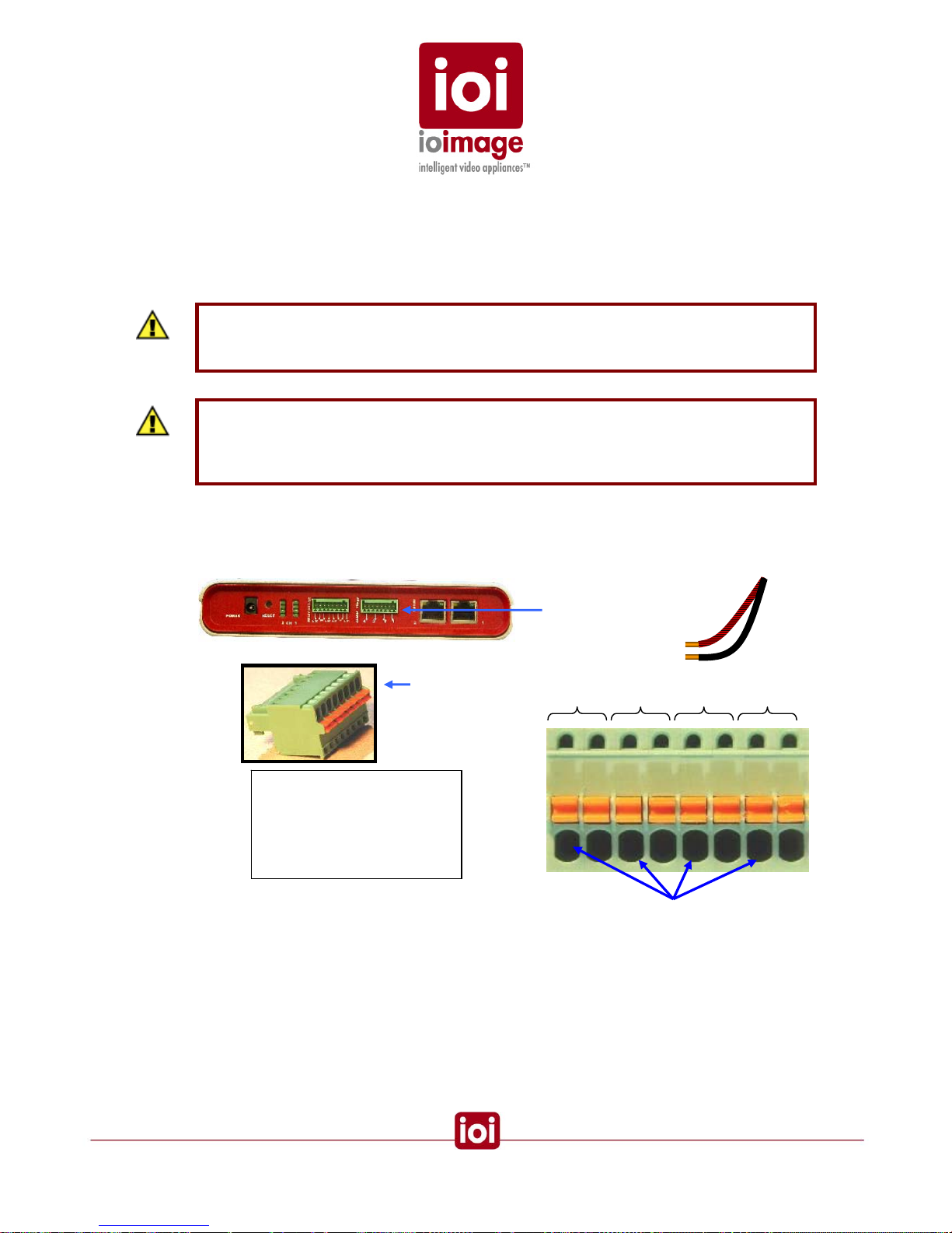
Accepts Alarm Lead Wires
Alarm Input
Terminal block
4 3 2 1
B A B A B A B A
Alarm Wire Contacts
A Side One
B Side Two
Common
Alarm Input Connection
If the Alarm Input wires are in a shielded, cable, connect the shielded wire to any of the common “B”
terminals.
29

Connecting PTZ Camera Controller Lines
Connection of the PTZ camera control lines to the ioibox unit can be made either with a RS232 or
an RS485 to the proper connector on the adapter cable.
If an RS232 cable is being used the connection between the ioibox unit and the PTZ camera
requires use of an RS232 to RS485/RS232 bi-directional converte r to be used.
This converter should meet the following requirements:
• Equipped with a DCE/DTE switch
• A minimum simplex and half duplex support
• Must support TxON from the ioibox unit to the PTZ camera
Once connected, the camera can be configured in the ioibox Setup software. This configuration
allows PTZ control of the specified camera using a remote PTZ controller.
The connection capabilities of the ioibox unit provide up to two connections to the RJ45 using the
adapter cable. Connections can be either RS232 or RS485 standard depending on which cable
connection you use.
The following are example procedures for connecting a Pelco Spectra III DD53CBW-X control lines.
As PTZ cameras vary the procedure for other PTZ cameras may be different.
Example Procedures:
• Connecting a PTZ Camera to the RS485 connection of the adapter cable (page 32)
• Connecting PTZ Camera Control Lines to RS232 DB9 (page 33)
30

Connecting PTZ Camera Control Lines to RS485 lead-wires
The following diagram shows the ioibox unit and the PTZ connection using an RS485 connection
on the adapter cable.
TRK
Adapter Cable
PTZ control lines connected with the adapter cable RS485 lead-wires
31

Connecting a PTZ Camera to the RS485 connection of the adapter cable
1. Insert and clamp the control lines of the adapter cable to the terminal block of
the camera:
a) Connect the orange TX- lead to the RX-.
b) Connect the yellow TX+ lead to the RX +.
2. Plug the RJ45 male end (ioimage RS232 DB9 to RJ45) into the ioibox unit
RS232/485 port.
32

Connecting PTZ Camera Control Lines to RS232 DB9
The following diagram shows the ioibox unit and the PTZ connection using an RS232
DB9connection on the adapter cable.
Connecting PTZ Camera Control Lines to RS232 DB9 on the ioibox unit
Connecting a PTZ Camera to the RS485 connection of the adapter cable (example
procedure)
1. Insert and clamp the control lines to the terminal block of the converter (RS232
to RS485 bidirectional converter):
a) Connect the TX- lead to the RX-.
b) Connect the TX+ lead to the RX+.
33
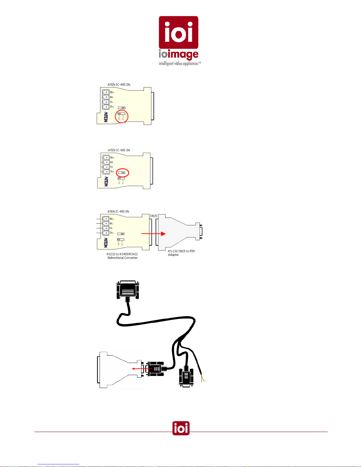
2. On the converter (RS232 to RS485), position the DCE/DTE switch to the DTE
position.
3. On the converter (RS232 to RS485), position the DTS/TX/RX switch to the
RX/TX-on position.
4. Connect the converter (
RS232 to RS485 bidirectional converter) to the adapter
(
RS232 D825 to DB9)
5. Attach DB9 female end to the (adapter cable - RS232 DB9 to RJ45) male
adapter.
6. Plug the RJ45 male end (ioimage RS232 DB9 to RJ45) into the ioibox unit
RS232/485 port.
34

Connecting ioibox unit Video Output to an Analog Device
The ioibox unit analog video output can be monitored or recorded on analog devices. The output
analog video contains the video from the camera combined with On Screen Display (OSD) overlays
such as, tracking boxes and trails, time stamp, alarm, camera status, etc. These OSD can be
enabled and customized using the ioibox Setup application. For more information, refer to the
ioibox HTML Edition Setup User Guide.
To Connect an Analog Device to the ioibox unit Analog Video Output
• Using video coax 75
cable, connect to the VIDEO OUT of the ioiboxCompact unit to the analog device video input of the external device (e.g.
the VIDEO IN of a monitor)
Connecting the External Protective Earth Terminal
ioimage units must have the external protective earth terminal permanently connected to protective
earth according to local regulations and codes.
To Connect the External Protective Earth Terminal
1. On the back of the ioimage unit, loose the screw of the protective earth
terminal.
2. Attach a properly rated ground cable according to local code requirements and
tighten the screw.
3. Assure that the other end of the ground cable is connected to protective earth
according to local regulations and codes.
Connecting the Power Supply
Connecting the electrical power to the ioibox unit is recommended as the last connection to be
made. Before connecting to the power, please review
Cautions and Warnings (page 1) and the
section
Electric/Power Supply Cables (page 7) sections.
Electrical safety should always be observed.
Warning
To prevent bodily injury or damage to the ioibox unit, only use properly rate and approved
power supplies.
:
To Connect the Power Supply
1. Connect the power from a properly rated power supply to the Power connector
on the unit panel.
2. Verify that the power LED (bottom light) on the back panel of the ioibox unit is
lit.
35

Setting the ioibox IP
There are two connectivity methods for configuring the ioibox IP and network settings:
1. Over the network (switch/hub)
If you need to change the default IP, gateway or the subnet mask, you can do
this over the LAN/WAN network using a web browser when the following
conditions are met:
• The IP of the machine accessing the ioibox-HTML setup application using
a Web Browser or running the ioimage SiteConfigurator application fits to
the subnet mask 255.255.255.0
• The network allows or has been configured for the factory shipped IP to be
visible to the machine where the ioibox-HTML setup application is
accessed from a Web Browser or where the SiteConfigurator is installed.
2. By a stand-alone computer connected to the ioibox if the following conditions
are met:
• Windows 2000/XP/Vista with a 10/100 Ethernet port
• If the computer’s IP fits to the subnet mask 255.255.252.0
• The computer’s local area connection settings allow or have been
configured to support the factory shipped IP to be visible.
If these conditions are not met, you may need to temporarily make changes to you network settings
to allow the configuration of the ioibox network settings to requirements and then manually restore
the network settings afterwards. This requires administrative permission and should only be done
by a network administrator who is authorized to change these settings.
One a connection is established and the network settings allow communication the IP can be
change using one of two methods:
• Setting the IP Using ioimage HTML Setup application
• Setting the IP Using the ioimage SiteConfigurator application
Preparation
1. Write down the factory default IP address.
2. After installing the ioibox, connecting it to the network or PC, as well as the
power supply, press the reset button on the back of the ioibox. For additional
reset options, see the
Resetting the ioibox units section (page 40).
3. Make certain this IP number is added to the LAN/WAN network configuration to
allow the IP to be visible to the workstation computer where the ioibox HTML
setup is installed.
Important: To avoid IP conflicts on units using the default IP address, only a single unit
should be connected to the network at a time until the IP addresses can are changed.
36

Setting the IP Using HTML Setup
Using and HTML browser (Internet Explorer 6 or 7) you can access Setup and make changes to the
IP and networks settings as needed.
The following table describes the labels and setting of the Network Basic settings screen.
Setting Description
General
Unit Name The name given to the unit.
IP Address
Obtain an IP
address
automatically
(DHCP)
Enables the unit to obtain an IP from a DHCP mechanism on the network.
Note: Selection of DHCP option when DHCP server is not available
may cause the unit to default to an arbitrary IP address that may be
incompatible with the network.
Use the following IP
address
In this mode, the trk1 IP must be entered in the IP Address box.
IP Address The IP number in standard format that is the IP of a trk1 used on the
LAN/WAN.
Subnet mask This is a mask that limits which network computers are allowed to access
the ioibox. This mask should be changed to match with your local network
numbering convention.
Default gateway This address is a local IP address, usually a router, on the local network
that serves to forward to another network beyond the local network. If your
network uses a switch (gateway). This is the IP address of that switch. If
your network uses a hub, this setting is not applicable.
To set the IP Using HTML Setup
1. Access the unit IP using Internet Explorer (may need to adjust security
settings, see the Network Settings and Requirements section.)
2. Access the unit via a web browser and then on the upper right mode menu,
click Setup.
A login prompt appears.
3. In the login prompt enter your login name (default admin) and password
(default admin) then click Login.
37
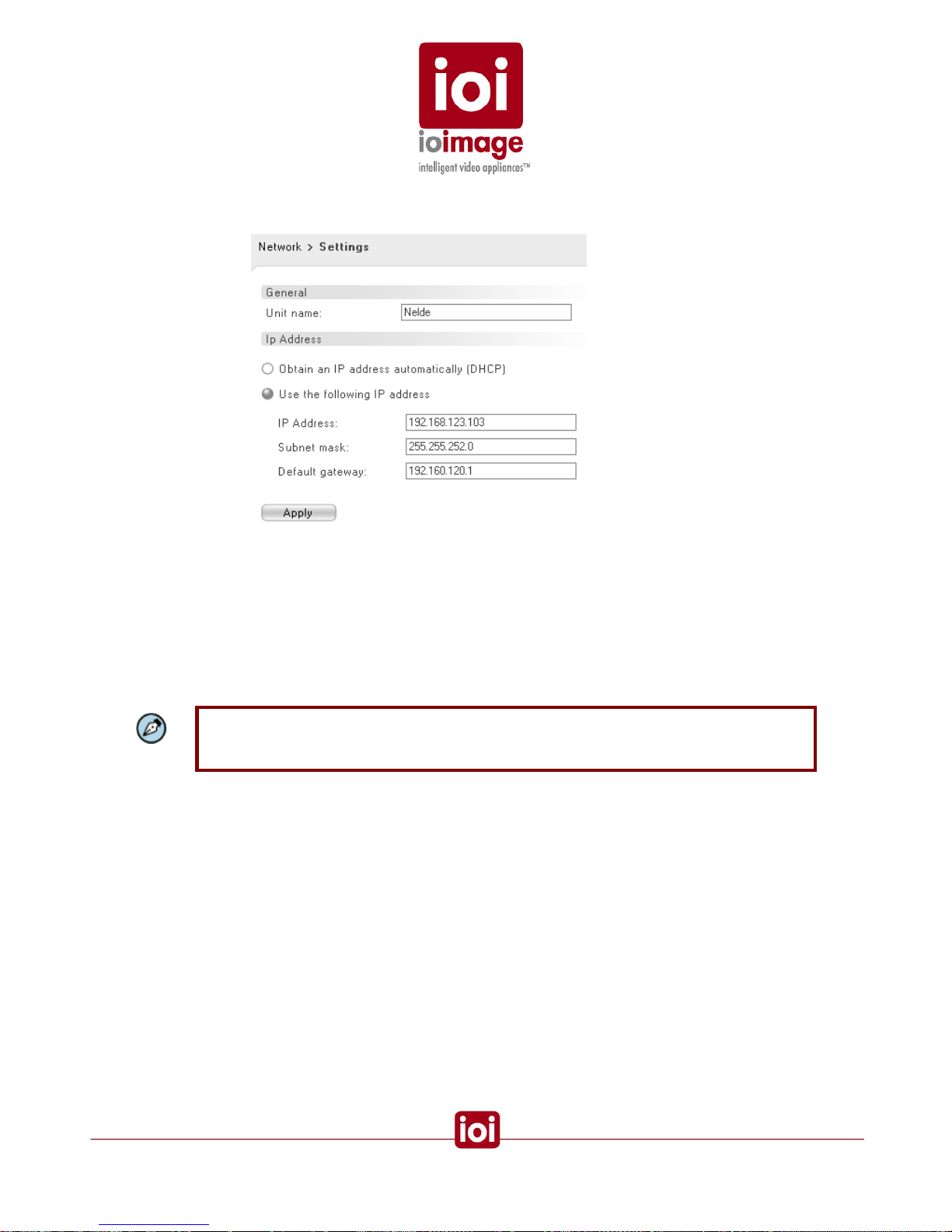
4. In the Configuration Navigation Menu, click the Network node and select
Settings.
The network settings screen appears.
5. In the Settings tab do the following:
a) If not selected, select Use the following IP addres s.
b) In the IP box, enter the IP number to be used.
c) In the subnet box, enter the subnet mask required for the network and specifically
with the machines that will be using and configuring the unit.
d) If on a WAN, in the Gateway box, enter the IP of the WAN gateway.
6. Click Apply.
Note: Selection of DHCP option when DHCP server is not available may cause the unit to
default to an arbitrary IP address that may be incompatible with the network making the unit
not visible on the network.
38

Setting the IP Using the SiteConfigurator Application
The network configuration can be changed using the SiteConfigurator applicatio n (See
Documentation & utilities CD provided with the unit). The benefit of this tool is that it displays and
allows configuration of connection settings for all ioimage ioiboxes and ioicams on the network.
Setting Description
IP The IP number in standard format that is the IP of an ioibox or
ioicam used on the LAN/WAN.
Subnet
Mask
This is a mask that limits which network computers are allowed to
access the ioibox. This mask should be changed to match with
your local network numbering convention.
Default
Gateway
A node (usually a router) on the computer network that serves as
an access point to another network. If your network uses a switch
(gateway). This is the IP address of that switch. If your network
uses a hub, this setting is not applicable.
To change the network settings using the SiteConfigurator
1. Start the SiteConfigurator.
The site configuration takes a few moments to display all of the network
resources on the network.
2. From the Network Resources select the ioibox or ioicam to be configured
3. Select the Network tab
4. In the Network tab, select the Module tab and do the following:
a) In the IP address box, enter the IP address to be used
b) In the Subnet mask, enter the mask for network communications
c) If on a WAN, in the Gateway box, enter the correct Gateway IP address.
5. Click Apply.
39

ioibox unit Network IP Assignment Modes – DHCP/Ma nual
There are two ways for configuring the ioibox unit Block IP numbers:
• Manual IP Configuration Mode
In this mode, the ioibox IP is user-defined and can be changed by using the ioiboxHTML setup application.
• Automatic IP Configuration Mode
In this mode, the ioibox unit Block IPs are defined by the DHCP server. This mode
works with DNS and DHCP mechanisms of the network that automatically handle IP
assignments. DHCP is a network server that works like an agent to maintain dynamic
IP assignment for network domains.
On initial connection, the ioibox unit automatically checks to see if there is a DHCP
(automatic IP assignment) feature on the network. If the ioibox unit is connected to a
non –DHCP network, or the DHCP fails to respond, the factory shipped Block IPs are
used.
If the network uses DHCP, the ioibox unit will request and use the IP numbers provided by the
DHCP.
Note: if you are using DHCP, it is recommended that the network be configured to associate
the MAC address with the DHCP assigned IP number. This will help prevent problems with
DHCP giving away a unit’s IP to another device.
Note: Selection of DHCP option when DHCP server is not available may cause the unit to
default to an arbitrary IP address that may be incompatible with the network making the unit
not visible on the network.
Resetting ioibox units
There are two ways to reset the ioibox units:
• Hard Reset Using the Reset Button on the unit
• Hard Reset Power Down and Power Up
Hard Reset Using the Reset Button on the unit
The ioibox unit has a Reset button located on the front of the ioibox unit that can be pressed to
reset a ioibox unit.
To Reset a ioibox unit Using the Reset Button
• Using a small pointed object, such as a ballpoint pen, insert the point into
the hole labeled “Reset”, press in and release.
Hard Reset Power Down/Power Up
The ioibox unit can be reset by turning on and off the units.
40

To Reset a ioibox unit by Power Down/Power Up
1. Turn off or disconnect the power supply plug.
2. Turn on the power or reconnect the power supply plug.
Camera Installation & Tips
The following provides general guidelines for configuring stationary and Pan Tilt Zoom (PTZ)
cameras.
• The TRK units only support analog signal and the Video Input of the TRK
unit white balance signal should be 1V p/p
• Connected video should be live when the TRK-unit is powered on.
• If the camera model supports Onscreen Displays, these displays should be
disabled.
• Analog PTZ cameras must have auto-focus. Assure that the camera auto
focus (AF) is enabled and manual focus (MF) disabled.
• For PTZ cameras, if the camera model has an automatic backlighting
feature (BLC), disabled it.
• Position the camera as best possible to avoid scenes that directly view the
sun at periods of the day.
• On cameras that have extendable sun shields, extend them as far as
possible – this increases the possibility of the sunshield protecting from
effects of the sun and the lens from dust and weather.
• If the camera model has image stabilizer functionality it should be enable.
• If the camera has built-in motion detection, disable it
• If the PTZ camera model supports privacy masking features, all privacy
masks should be disabled.
• If the PTZ camera model has proportional pan and tilt it must be disabled.
• If the camera has OSD, they should be disabled.
• If the camera model has a shutter speed setting that is automatically
reduced during night, disable this functionality.
• The camera should be adjusted for clarity of the objects and not
necessarily the best aesthetics. Adjust the sharpness, brightness, and gain
(on the camera itself) should be optimally set to this effect.
• Adjust the focus as follows:
o For all cameras, adjust the focus during the day to best view of the area of
interest. Final focusing always during the night
o For day night cameras that have two camera, adjust each camera for it
day or night application to best view of the area of interest
• For the lens of the camera:
41

o Many standard cameras lenses automatically filter out infrared during the
daytime. If you are using a camera working with infrared illumination that is
a “night” camera, select a lens that doesn’t filter out infrared. Use a lens
that compensates for daytime infrared but supports infrared at night.
o Choose a lens that provides sufficient field of view magnification, so that
the intruders can be detected at the depths required for the site. Note the
greater the magnification the less width in the field of view.
• Camera height and angles:
o For FOVs of depth where movement towards the camera is to be
detected, the camera angle and height should be adjusted based on the
FOV depth, topology/detection plane angle of intersect. In general, greater
heights with smaller inner (steeper) angles provide more pronounced
visualization of movement on the detection plane towards or away from
the camera. If to large of a camera angle (tilt approaching parallel in
relation to the detection plane) and low camera height are used,
visualization of movement towards or away from the camera will be less
pronounced. This may affect the speed of detection if an intruder makes a
precise foreword or away movement (no significant horizontal) because
the pixel distance translations will be more difficult to gauge. One pixel
change, in this situation, will be equivalent to a considerable distance
traveled. Wide-angle lenses will provide less depth capabilities at
distances, as the intruder will appear smaller at close to 90° (relation to the
primary detection plane).
42

o The following image shows how from the camera’s point of view the angle
at which an intruder is viewed, becomes greater at a distance and thus
quality of visible progression towards of away from the camera is less
pronounced.
The view nearer the camera is at a steeper angle and therefore the depth
more accurate (more pixels per movement at a set distance) in
determining depth movements towards or away from the camera. If a
camera is mounted at 90° to the detection plane an approaching object
only grows in size but does not show movement in reference to the
detection plane.
• Lighting Issues
o For scenes of depth, lighting should always be behind the camera and not
in the front. If the lighting is in front of the camera it may cause the auto iris
to automatically adjust to close light and this will reduce visibility at depth
where the light is not as strong.
o Lighting (including infrared) should not be directed at the ground in front of
the camera but is preferential that it be projected near parallel to the
ground. This is because if the foreground is brightly lit the auto iris may
adjust and reduce visibility at depth where the light is not as strong.
o If using white or yellow lighting, use a LUX meter and measure the lighting
by facing the meter down. The reading for areas that will support detection
in white or yellow light cameras should read at 5lux or greater.
o If using an infrared illuminator, check that the sensitivity of the camera chip
matches the illuminator specifications.
• Camera placement:
o The tripwire functionality performs optimally when the camera is positioned
to point down the tripwire line of separation.
Overhead view of an optimal camera view down the line of a tripwire
43

o When the PTZ synchronization is used the PTZ camera must translate the
stationary cameras three-dimensional coordinates to its own preset scene
coordinated. In a previous paragraph the inherent effects of angle and
gauging distance was discussed. In a situation where the stationary
camera sends a less than precise depth coordinate, most often
synchronization can overcome errors using the other two coordinates. If
however, the PTZ camera is at a near 90 intersect with a stationary
camera the margin of error in distance coordinate becomes mo re
pronounced as individual pixels can translate into several meters on the
horizontal pan of the PTZ.
For planning the intersection angles of a PTZ and stationary camera, the
following guides for understanding the level of accuracy on a PTZ handoff
at the different PTZ to stationary intersect angles (horizontal) for different
visual & camera angles (vertical) on a stationary camera:
For a stationary camera with a low camera angle or visual angle (vertical)
the following shows the advantages and disadvantages of intersecting
between a PTZ camera (
) and a stationary camera:
For a stationary camera with medium camera angle or visual angle
(vertical) the following shows the various qualities at installation angles
where the PTZ and stationary synch share (horizontal intersect angles) a
view of an intruder:
44

For a stationary camera with a steep camera angle or visual angle (vertical
angle) the following shows the qualities at installation angles where the
PTZ and stationary synch share (horizontal intersect angles) a view of an
intruder:
o If an area is sizable and requires more than one camera place the
cameras so that the field of views overlap sufficiently so that there are no
dead zones between them. Factors of lens selection, camera height, depth
and width of view will determine the capabilities of the cameras to cover
any given FOV area. The overlap should be such that the area of overlap
provides the ability to view the full top-to-bottom height of an intruder by
the camera covering the dead zone of another camera.
45

o Cameras should be place so that one camera provides an overlapping
view of the other. In this way, should an attempt to tamper or disable a
camera can be capture in the surveillance FOV of the covering camera.
o When determining camera height and installation area, consideration for
accessing the camera for maintenance, camera security, lighting qualities,
cabling requirements (factors signal degradation) and FOV coverage
should all be considered.
• PTZ Cameras
o If the PTZ Camera supports digital zoom, the digital zoom should be
disabled or adjusted to full zoom out. Current support for zoom uses
optical zoom commands.
o If the camera supports zoom speed settings, refer to the ioimage support
downloads on the ioimage website (www.ioimage.com) for tech sheet on
the optimal setting.
o Disconnect any attached keyboards or controllers except for ioibox unit
connection. Use of a splitter and dual controls may cause interference with
ioibox unit operations.
o If the camera model supports sync settings, change the synch setting to
internal synchronization.
• Regular cleaning and maintenance of the camera should be scheduled.
46

Appendix
The appendix contains the following sections:
• Connecting Leads to a Spring Clamp Terminal Block (page 47)
• Troubleshooting (page 48)
• How to Ping a ioibox unit from a Workstation (page 51)
• Connector Mapping Tables (page 52)
• Compact ioibox Specs (page Error! Bookmark not defined.)
• Who to Contact (page 55)
Connecting Leads to a Spring Clamp Terminal Block
The ioibox units come with two terminal block connectors. Each connector is for terminating wires
and then plugging the connector into either the Relay Output or Alarm Inputs of the ioibox unit.
To Connect a Wire to the Spring Clamp Terminal Block
Spring Clamp Terminal Block
1. With a small screwdriver, press in and hold the orange spring-clamp button
next to the female outlet where the wire will be inserted.
2. Insert the wire in the female outlet. Note the wire end should be stripped of
insulation.
3. Release the orange spring-clamp button.
Connecting a Wire to a Terminal Block
47

Troubleshooting
This section provides useful information and remedies for common situations where probl ems may
be encountered.
Problem Try
No Lights Check the power is turned on at the source, includes checking GFI,
Breakers, UPS, etc.
Check the power supply connections to the ioibox unit, between the IEC
cord and to the power source.
Reset the ioibox unit.
Check the power supply is working.
Unplug the ioibox unit and have it serviced.
No Ethernet 10/100
Lights (connected to the
Ethernet with other
lights working)
Check that the network is working.
Check that the Ethernet cable is properly attached.
Check the Ethernet cables for damage and replace as needed.
How to find out what IP
is being used
Use the SiteConfigurator to detect the units on the network
The ioibox unit Block IP
is already in use by
another computer
(collision)
Using the ioibox HTML setup or SiteConfigurator application to change
the ioibox IP after connecting to it directly (not through the system
network).
The ioibox unit has
different IP than what is
marked on the box.
If this is the initial setup and the ioibox unit is using an IP other than the
IP marked on the unit, chances are that you network uses DHCP that
has dynamically assigned a network compatible IP when the ioibox unit
was initially installed. This should not be a problem. Note that you
should contact the Network Administrator and see if there is a DHCP
feature for assigning the same IP to a specific ioibox unit MAC address.
This will assure the IP does not change in the future.
If there is no DHCP feature on the network, then the ioibox unit may
have been configured to a different IP or the label on the unit is
incorrect.
You can change the IP if necessary; see the
Setting the ioibox unit IP
section (page 36).
The DHCP has changed
the ioibox unit IP and
given the initial IP to a
different device
Because DHCP is a dynamic agent that provides IPs to requestors
there is a possibility that an IP can be mistakenly given away. Consult
your Network Administrator about preventing this situation. Commonly
there is the ability in the DHCP mechanism to link IP numbers to MAC
addresses. By doing so, this will instruct the DHCP not to give the IP to
another device.
48

Problem Try
No analog output video
signal
Check that the video cables are securely connected between the i oibox
unit Video OUT jack and the analog video device.
Check that the connection is made to the correct VIDEO IN jack of the
analog video device.
Verify that the ioibox unit has power.
Check the cables for damage and replace as needed
Bad output video quality Check the cables are connected securely. This includes junction boxes
and amplifier that may be used.
Check the camera settings are correct, on the camera and in the ioibox
Setup software.
Check the camera lens is clean and unobstructed
Check the cable length is within specifications
Streaming video image
is hanging (stopped)
Refresh Browser screen (F5)
Check the network is operating correctly
Check the ioibox Setup configuration is correct for the available CPU
and network traffic.
The PTZ camera control
doesn’t work
Check that the correct camera type is selected in the ioibox Setup
software
If using an RS232 DB9 of the adapter cable, you will need to install a
bidirectional converter RS232 to RS485 and position its switches
correctly, such as DTE and TxOn. For more information, see
Connecting PTZ Camera Control Lines (Remote Control), page 30.
Check the PTZ control leads are securely connected to the terminal
block connector.
Check the PTZ control leads are connected to the correct pins of the
DB9 RS232 or RS485 wires. Also verify that no more than two of any
combination of these connections are used from the adapter cable
connected to a single port on the ioibox unit. See the
Overview of
RS232 Connections section (page 21), for more details.
Verify that the output to the ioibox RS232/485 input is correct.
If PTZ camera requires an RS485 standard, use a RS232 to RS485
bidirectional converter as needed.
If using a RS232 to RS485 bidirectional converter, check that the
bidirectional converter DCT/DTE switch is set to DTE and that the
DTS/TX/RX switch is set to RX/TX-on position.
The wrong PTZ camera
moves on events
Check in the ioibox Setup software that the correct PTZ camera is
correctly configured to the proper RS232.
Check that the control leads are connected to the correct RS232/485
channel
49

Problem Try
Alarm Inputs (Dry
contacts) are not
working
Check a proper rule for an alarm input event was defined in the unit
using the HTML setup application
Check that the ioibox is communicating through the network.
Check the HTML setup to assure the Alarm Input is enabled.
Check the Alarm inputs wires are connected securely.
Check that the alarm wires are paired in the terminal block according to
requirements.
Check that the block connector is plugged in firmly to the Alarm Inputs
and not the Relay Output.
Check that the Alarm Input (Dry contact Close/open) is being provided
by the connected device.
Relay Output is not
working
Check a proper rule for an alarm input event was defined in the unit
using the HTML setup application
Check that the Relay Output is properly configured in the ioibox Setup
software.
Check the Relay Output wires are connected securely.
Check that the Relay Output are paired in the terminal block according
to requirements and that one wire is connected to the common.
Check that the NO or NC match the system Normally Open or Normally
closed configuration.
Check that the block connector is plugged in firmly to the Relay Output
and not the Alarm Inputs.
The ioibox unit
continuously reboots
Check that the camera is on and sending a signal before powering up
the ioibox unit
Check the Video In connection is secure between the camera device
output and the ioibox unit.
Check that the live signal at the Video In has white balance signal 1V
p/p
50

How to Ping a ioibox unit from a Workstation
You can check if an ioibox IP is accessible over the network by using the command shell and
issuing a ping command from a PC.
In order to ping an ioibox IP, you will need its IP address.
If the command window shows a “Reply” the ioibox is visible and working.
If the command window shows “Request timed out” the ioibox unit at the IP specified is not being
reached through the network or is not working.
To Ping a ioibox unit
1. In Microsoft Windows®, select StartRun.
The run dialog appears.
2. Type “cmd” or “command” and click OK.
3. In the command shell window, type “ping”, press SPACE, type the IP address
of the unit and press RETURN.
Successful ping showing “Reply” from an IP
4. To exit the command window, type “exit” and press RETURN.
51

Connector Mapping Tables
RS232
Pin Desc.
1 TX+ (2)
2 TX- (2)
3 GnD (2)
4 TxD (1)
5 RxD (1)
6 GnD (1)
7 RxD (2)
8 TxD (2)
RS232
DB-9
Pin Desc.
2 RxD
3 TxD
Channel 1
5 GnD
Channel 2
RS485 (option 2)
Terminal Block
Pin Desc
A Rx+/B Tx+/.
RS232 (option 1)
DB-9
Pin Desc.
2 RxD
3 TxD
5 GnD
RS232/485 Pin Diagram
52

Specifications
trk100 trk100d trk200
Channels
Number of Intelligent Video Analysis Channels 1 1 2
Analog Video Inputs
TV Standard Composite – NTSC or PAL
Physical Connector
1 x BNC 75
2 x BNC 75
Analog Video Outputs
TV Standard Composite 1Vp-p – NTSC or PAL
Physical Connector
1 x BNC 75
2 x BNC 75
Digital Video Output
IP video streaming MPEG4 SP
Max Resolution per Channel CIF 4CIF CIF
Frame Rate Up to full frame rate
Bit Rate CBR (128Kbps – 4Mbps)
Network
Ethernet (IEEE 802.3/802.3U) 2x RJ-45 Interface
Services and Protocols TCP/IP, UDP/IP, HTTP, SMTP, DHCP, DNS, SNTP
Video streaming RTP/RTSP
Alarms /Commands TCP/IP
I/O Interface
Serial (may use one interface per input for PTZ camera control) 2x RS-232 + 1x RS-485
IN – Alarm Input 4 x Dry Contacts
OUT – Relay Output 2 x Relay Output (rated load 0.3A @ 125VAC / 1A @ 30VDC)
Power Source
Voltage 12VDC
Power over Ethernet (PoE) Not Supported
Power Consumption 5.5W 8W 8W
Physical Dimensions
Dimensions (mm) 189 x 36 x 164 mm (W x H x D)
Dimensions (Inches) 7 7/16" x 1 13/32" x 6 7/16" (W x H x D)
Mounting Shelf mount
Environmental Specifications
Operating Temperature 0° to 50° C
Operating Humidity 5% to 95% (Non-Condensing)
Certifications
Safety UL, CE
Electromagnetic Interference (EMC) FCC 47 CFR part 14 subpart B, Class A / CE, Class A
53

Who to Contact
For information, service or sales, contact your ioimage integrator. For additional contact
information, visit the ioimage website at www.ioimage.com.
• For North America:
ioimage US
109 S. Woodrow Lane #700
Denton, TX 76205
USA
Toll Free: 1-877-383-2913
Tel: +1-940-383-2913
Fax: +1-940-383-2967
Support Email:
us-support@ioimage.com
Website:
http://www.ioimage.com
Support Hours: Monday through Friday 9:00 – 20:00 CST (UTC/GMT-6)
• For Worldwide:
ioimage Israel Help Desk
Tel: +972-9-954-6003
Fax: +972-9-954-6004
Email:
support@ioimage.com
Website:
http://www.ioimage.com
Hours: Sunday through Thursday 8:00 – 20:00 Israel Time (UTC/GMT+2)
Have the following information available:
• Caller details
• ioibox unit serial number
• Description of the problem
54
 Loading...