

ioi FWBU2SATA35DMR, FWBUFISATA35DMR, FWBUF2SATA35DMR Installation Manual
Mirror Drive
2
FWBU2SATA35DMR/UF2SATA35DMR/UFISATA35DMR/U2SATA35DMR
Installation Guide
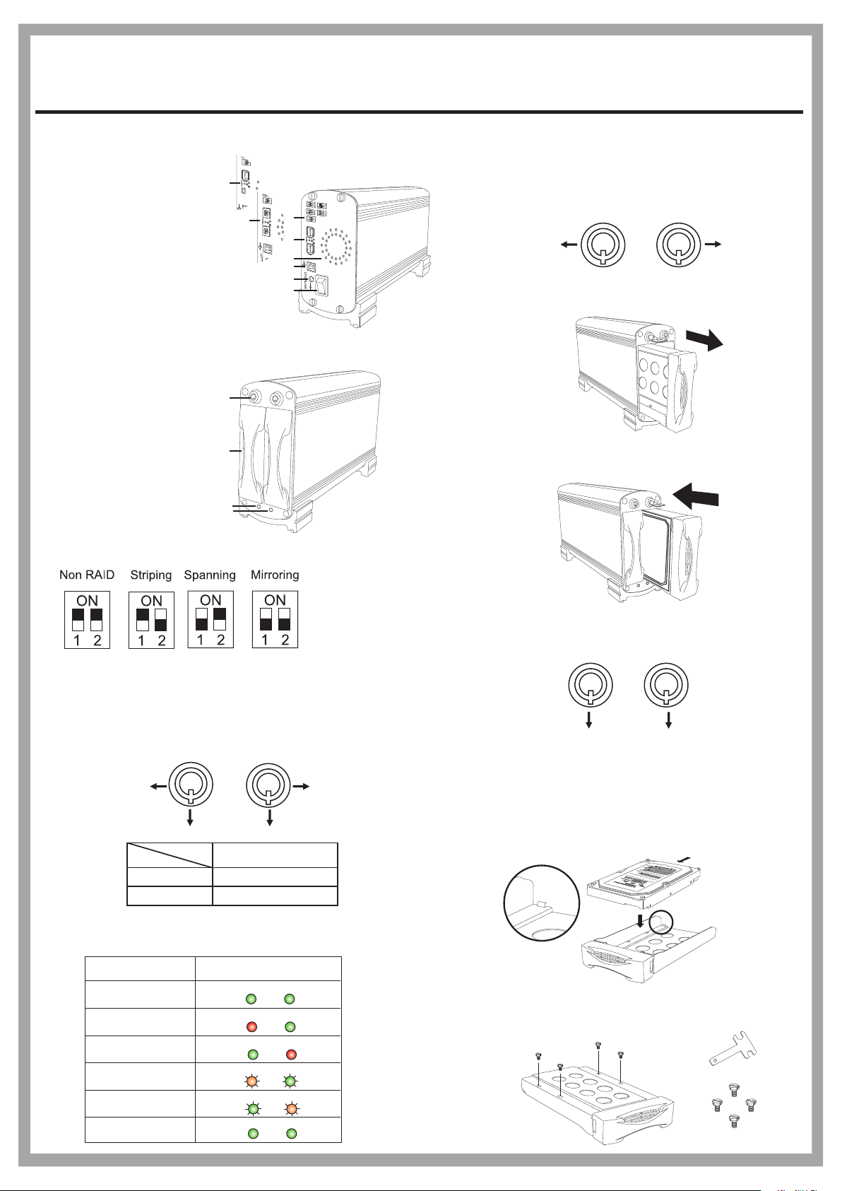
Panel Introduction
1. RAID Setting Switch
2. FireWire Connector
FireWire-6pin (only for UF2SATA35DMR)
FireWire-6pin + iLink-4pin (only for UFISATA35DMR)
Bilingual-9pin (only for FWBU2SATA35DMR)
3. USB B Connector
4. DC Power Jack (12V/4.16A)
5. Power Switch
6. Cooling Fan
7. Key lock
8. SATA HDD Mobile Tray
9. HDD 1 Status LED
(Green & Red)
10. HDD 2 Status LED
(Green & Red)
Jumper
1
1-1
2
7
8
9
10
1
2
6
3
4
5
1-2
1-3
How to Remove and Insert the Mobile Tray
To unlock the tray, insert the key and push to turn
the lock to Position A.
Note: The key cannot be removed when the lock is in Position A.
A
To remove the tray, grab the mobile tray firmly
and pull the tray from the housing gently.
To insert the tray, grab the mobile tray firmly and push
the mobile tray back into the housing.
A
- Non-RAID: for one or two disks
- RAID 0 (Striping): for two disks with same capacity.
- Disk Spanning: for two disks with different capacity.
- RAID 1 (Mirroring): for two disks with same capacity.
Key lock
A
Segment
HDD1
B
Status
B
A
HDD2
A
B
Security status
Locked (Non-removable)
Unlocked (Removable)
Power Indicator and HDD Access Indicator
According different statuses, the indicator displays are as followed:
Status Display
Normal State
HDD 1 Failed
HDD 2 Failed
HDD 1 under Rebuilding
HDD 2 under Rebuilding
HDD Duplicating
is completed
Green Green
Red Green
Green Red
Red/Orange Green
Blinking
Green Red/Orange
Blinking
Green Green
Blinking
Blinking
To lock the tray in place, turn the lock back to
1-4
Position B.
Note: The key can be removed while the lock is in Position B.
B
2
2-1
How to Install the SATA HDD
To install the SATA HDD, simply place the HDD
inside the tray as illustrated below. (A stopper in
the rear of the tray is provided to avoid careless
handling.)
2-2
After placing the HDD inside the tray, adjust and
secure the HDD with the provided screwdriver
and four hex-head #6-32 UNC screws.
B
SATA connector
T-shape screw driver
Hex-head #6-32 UNC
1
Mirror Drive
FWBU2SATA35DMR/UF2SATA35DMR/UFISATA35DMR/U2SATA35DMR
Installation Guide
3
3-1
3-2
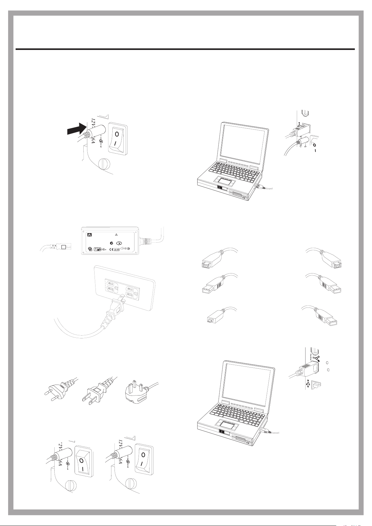
How to install AC-to-DC power adapter
Attach the DC power plug to the DC input of
the Mirror Drive.
Note: Push the power switch to turn off the power before
you attach the DC Power plug to the DC input.
Turn off
Plug one end of the AC power cord to the ACto-DC power adapter and the other end to the
AC power socket.
AC Input
JENT EC TEC HNOLO GY CO., LTD.
AC ADAPT OR
MODEL : J TA0202 Y
AC INPU T : 100 -240Vac /1.2A
50-60H z
DC OUTP UT : +5 V/2A, +12V/ 2A
+12V+12V
+5V+5V
RTNRTN
CAUTION:
RISK OF ELECTRIC
SHOCK
DRY LOCATION ONLY
INDOOR USE ONLY
N136
KETI-HU101 70-30 01
Q03305
LISTED
E227163
43DG
I.T.E.
Made in C hina E L
D33190
DC Output
4
4-1
4-2
How to connect the mirror drive and the computer
The Mirror Drive and the computer can be connected
by using either USB 2.0 or FireWire (IEEE 1394) serial
bus in a plug-and-play fashion.
Through USB connection:
use USB A-plug-to-B-plug cable.
USB A plug to B plug cable
Through FireWire (IEEE 1394) connection:
Beta plug to Beta plug cable
Only For FWBU2SATA35DMR
3-3
Power Code
Europ North America British Standard
(EN 50075) (NEMA 1-15P) (B5 1363A)
Push the power switch to on/off (1/0) of the
mirror drive.
FireWire plug to FireWire plug cable
Only For UF2SATA35DMR
iLink plug to FireWire plug Cable
Only For UFISATA35DMR
Turn on
Turn off
2
 Loading...