

ZP3-HCMS Installation and Operation Instructions
(Versions 301) 2 Heat / 2 Cool - Auto Changeover
First Call Priority - Time Share
HVAC Controls
Sequence of Operation:
The ZP3-HCMS is a residential / light commercial
zone control system that allows a single HVAC
unit to have up to three separate zones. Each
zone is controlled by its own space thermostat
and motorized zone damper. If a zone thermostat
calls for heating or cooling, the zones not calling
will have their dampers powered closed, and the
zone calling will have its damper opened. The
heating or cooling equipment will also be brought
on at the same time. When the zone calling is
satisfied, the heating or cooling equipment turns
off. If one zone calls for heating and another zone
calls for cooling, the first zone to call receives
priority. When the first call is satisfied, the system
will changeover and take care of the opposite call.
If a zone being served (heating or cooling) has not
been satisfied within 20 minutes while an opposite
call is taking place, the system will changeover.
When the zone is satisfied or 20 minutes has
elapsed, the system will again changeover if an
opposite call exists. This is referred to as Auto
Changeover - First Call Priority - Time Share. In
the event of a tie, cooling willreceive priority.
High and Low Limit Protection:
The ZPA-DTS Discharge Temperature Sensor
should be mounted on the discharge air plenum
of the HVAC unit and wired to the DA terminals on
the panel. The sensor is used for both high and
low limit protection. The high limit setting can be
adjusted using the two slide switches located on
the panel. (See switch location and settings on
page 2) The low limit is fixed at 45° F. When the
discharge air temperature rises above the high
limit setting or falls below the low limit setting, the
panel will cycle the equipment off while the fan
continues to run. The LIMIT LED blinks when
high or low limit is reached.
Ventilation Mode:
Zone ventilation is established by the individual
zone thermostat fan setting. Any thermostat set
in the fan AUTO mode will not receive ventilation
air when there are no heating or cooling calls.
Any thermostat set in the fan ON mode will
receive ventilation air whenever there are no
heating or cooling calls.
Power Requirements:
The ZP3-HCMS requires a separate 24 Vac
transformer. A 40 VA transformer will power the
panel and up to four (4) dampers. A 75 VA
transformer will power the panel and up to seven
(7) dampers. If more than three (3) dampers for
an individual zone are required, a RY-1-HB relay
should be used with an additional properly sized
transformer. iO Systems HD-XXXX rectangular
and D-XX round dampers are powered closed /
spring return open. Damper actuators are rated
at 10 VA. If 3-wire dampers (powered open /
powered closed) are installed, VA ratings will
vary depending on the damper actuator used.
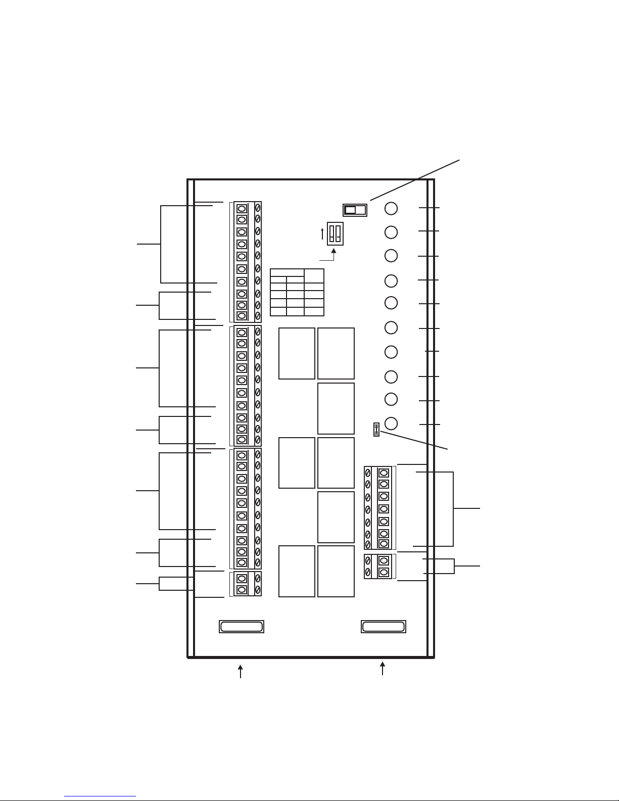
Wiring:
All wiring should be conventional 18 gauge
thermostat wire. Thermostats and zone dampers
may be located up to 300 feet from the
ZP3-HCMS panel.
ZP3-HCMS Installation and Operation Instructions
(Versions 301) 2 Heat / 2 Cool - Auto Changeover
First Call Priority - Time Share
(When set to ON, fan will
continue to run and air will
be purged to last zone
calling for 1 minute
after call is satisfied)
ZONE 1
THERMOSTAT
ZONE 1
DAMPER
ZONE 2
THERMOSTAT
ZONE 2
DAMPER
ZONE 3
THERMOSTAT
ZONE 3
DAMPER
24 VOLTS
THERMOSTAT
ZONE 1
DAMPER
THERMOSTAT
ZONE 2
DAMPER
THERMOSTAT
ZONE 3
DAMPER
POWER
24VAC
W1
W2
PC
PO
W1
W2
PC
PO
W1
W2
PC
PO
Y1
Y2
Y1
Y2
Y1
Y2
301HC
C
R
ADJUSTABLE
HIGH LIMIT
SWITCH
G
C
1
OFF OFF 130
ON OFF 140
OFF ON 150
ON ON 160
LIMIT
2
C
R
G
C
C
R
G
C
R
X
PURGE
OFF
ON
12
ON
RC/RH
JUMPER
24V
W1
W2
Y1
Y2
G
LIMIT
ZD1
ZD2
ZD3
RH
RC
W1
W2
Y1
Y2
G
DA
DA
24 VOLT POWER LED
FIRST STAGE HEAT LED
SECOND STAGE HEAT LED
FIRST STAGE COOL LED
SECOND STAGE COOL LED
FAN LED
HIGH / LOW LIMIT LED
ZONE 1 DAMPER LED
ZONE 2 DAMPER LED
ZONE 3 DAMPER LED
RH/RC JUMPER
TERMINALS
HVAC UNIT
SENSOR
PURGE
SWITCH
HVAC UNIT
DISCHARGE
TEMPERATURE
SENSOR
4 Amp fuse protects
printed circuit board
4 AMP 4 AMP
ZONE SYSTEM
4 AMP
4 Amp fuse protects
the relay contacts
HVAC EQUIPMENT
4 AMP

ZP3-HCMS Installation and Operation Instructions
(Versions 301) 2 Heat / 2 Cool - Auto Changeover
First Call Priority - Time Share
Installation
Mounting the Panel:
Carefully remove the ZP3-HCMS panel and
cover from the shipping carton. Slide the PC
board out of the snap track base and mount the
base to a flat surface either on or near the HVAC
indoor unit in an area that will facilitate easy
access for wiring. Reinstall the PC board by
carefully centering it over the base and snapping
it back into the track groves.
Wiring the Zone Thermostats and Dampers:
Refer to the logic panel wiring diagram. Wire
zone 1 thermostat and its associated damper to
the ZONE 1 terminals on the logic panel. Wire
zone 2 and 3 thermostats and dampers in the
same manner.
Wiring the HVAC Equipment:
Wire the HVAC unit to the panel terminals. Do not
wire the equipment common to the ZP3-HCMS
panel.
Installing and Wiring the ZPA-DTS
Discharge Temperature Sensor:
Drill a 15/32” hole in the middle of the main
discharge air plenum approximately 18” to 30”
from the heat pump electric strip heater or the
furnace heat exchanger in a fossil fuel
application. Slide the discharge air probe into the
hole and use two self-tapping sheet metal
screws to secure the base to the plenum. Use
conventional 18-2 thermostat wire and wire nuts
to attach the sensor leads. Replace the cover
with the wire nut connections inside. Strip 1/8”
insulation off of each wire at the other end and
and the wires to the screw terminals marked DA
on the panel.
Wiring the Transformer:
Wire a separate 24 Volt transformer of the proper
VA to the logic panel terminals marked (R) and
(X). Do not power the panel up until wiring is
completed.
Test, Check and Startup:
1. Verify that all component wires have been
connected to the proper terminals and are secure.
2. Disconnect the HVAC equipment (R) terminal
wire at the panel and apply 24 Voltsto panel.
3. Take a jumper wire and momentarily short the
DA terminals. This will put the panel’s time delays
in “speed up” mode.
4. Place the zone thermostats in the OFF position.
5. The panel accepts 2-wire (power close / spring
open) or 3-wire (power open / power close) zone
dampers. 2-wire dampers should be wired to the
(C) and (PC) terminals.
6. Place zone one thermostat in the fan ON mode.
ZD1 LED will remain on and ZD2 and ZD3 LED
will go out. The (G) FAN LED will come on.
7. Confirm that zone one damper is in the open
position and zone two and three dampers are
closed.
8. Leave zone one thermostatin fan ON and place
zone two thermostat in the fan ON mode. ZD2
LED will come on.
9. Confirm that both zone one and zone two
dampers are in the open position and zone three
damper is closed.
10. Leave zone one and zone two thermostats in
Fan ON and place zone three thermostat in the
fan ON mode. ZD3 LED will come on. Confirm
that all zone dampers are in the open position.
11. Place all zone thermostats in the Auto fan
mode.
12. Remove 24 Volts to the panel and reconnect
the HVAC ® wire.
10. When 24 Volts is applied again to the panel,
the internal time delays will be activated.
11. Place zone thermostats in proper mode of
operation.
12. Confirm that the LIMIT LED is ON. If not,
check LIMIT wiring. If the system goes out on high
or low limit, the LIMIT LED will blink.

ZP3-HCMS Installation and Operation Instructions
(Versions 301) 2 Heat / 2 Cool - Auto Changeover
First Call Priority - Time Share
Specifications
Panel Dimensions:
Height: 8.0 Inches
Width: 6.0 Inches
Depth: 1.375 Inches
Mounting:
Snap Track with 2 back plate screws
Operating Temperature Rating:
-40° F to 150° F
Operating Humidity:
5% to 90% RH non-condensing
Wiring:
18-gauge wire for all equipment
and system connections
Time Delays:
3 minutes minimum off between
cooling calls
3 minutes minimum off on low limit
20 minute time share
Purge ON = 1 minute
Thermostats:
Single or multi-stage heat / cool
Programmable or non-programmable
Auto or manual changeover
ZONE 3
STAT
ZONE DAMPER 3
Dampers:
PC Powered Closed
C Common
PO Powered Open
High / Low Limit
DA Land to ZPA-DTS
DA Land to ZPA-DTS
HVAC Equipment:
RH 24Vac Heating Transformer
RC 24Vac Cooling Transformer
W1 First Stage Heat
W2 Second Stage Heat
Y1 First Stage Cool
Y2 Second Stage Cool
G Fan
Panel Power:
R 24Vac (Hot)
X 24Vac (Common)
ZONE 2
STAT
ZONE DAMPER 2
ZONE 1
STAT
ZONE DAMPER 1
Terminal Designations
Thermostats:
C 24Vac (Common)
R 24Vac (Hot)
W1 First Stage Heat
W2 Second Stage Heat
Y1 First Stage Cool
Y2 Second Stage Cool
G Fan
HVAC Controls
Indianapolis, IN 46237
DISCHARGE
TEMPERATURE
SENSOR
ZP3-HCMS
PANEL
24 VOLT
TRANSFORMER
FURNACE
www.iohvaccontrols.com
For Technical Support Call Toll Free: 866-225-5032
iO-06-1168-010818
 Loading...