

IO-Homecontrol HPWH 200 COZY, HPWH 270 COZY, HPWH 200 COIL COZY, HPWH 270 COIL COZY User's Installation And Operation Manual
Page 1
Documentation for
installation and
operation
HPWH 200 COZY
HPWH 200 COIL COZY
HPWH 270 COZY
HPWH 270 COIL COZY
Heat pump water heater
Page 2
WARNINGS
This appliance is not designed for use by people (including children) of
reduced physical, sensory or mental capacity, or those inexperienced or not
understanding this manual unless they have received prior instruction or
supervision from someone responsible for their safety, about the use of the
appliance.
Children must be supervised to ensure they do not play with the appliance.
This appliance may be used by children of 8 years or over, and by people of
reduced physical, sensory or mental capacity, or those inexperienced or
ignorant if they are properly supervised or if they have been given
instructions about the safe use of the appliance, and made aware of the
associated risks. Children must not play with the appliance. Children must
not clean or maintain the appliance without supervision.
INSTALLATION
WARNING: Product heavy, handle with care:
1/Install the appliance in a frost-free room. The warranty does not cover
destruction of the appliance through excess pressure caused by a blockage in
the safety valve.
2/Ensure that the wall on which it is mounted can support the weight of the
appliance filled with water.
3/If the appliance has to be installed in a room or location with an ambient
temperature always above 35°C, this room must be ventilated.
4/Place the appliance in an accessible place.
5/Refer to the installation diagrams.
The size of space needed for the
appliance to be correctly installed
is specified in the chapter installation.
It is mandatory for the water heater
to be fixed to the floor using the
fixing attachment provided.
The user keep this manual
1
Page 3

WARNINGS
WATER CONNECTION
A new safety unit must be installed at the intake to the water heater, in a
frost-free environment, with dimensions of 3/4" and with pressure of 7 bar -
0.7 MPa, compliant with local regulations in force.
A pressure reducer (not supplied) is needed when pressure is more than 5
bar (0.5 MPa) and it will be placed on the main supply.
Connect the safety unit to a drain pipe kept in the open air, in a frost-free
environment, with a permanent downward gradient, to remove any
expansion water from the heating process, or drainage water from the waterheater.
The operating pressure of the heat exchanger circuit must not exceed 3 bar -
0.3 Mpa, and its temperature must not be higher than 85°C.
ELECTRIC CABLING
Before removing the cover, always make sure that the power is turned off, to
prevent any risk of injury or electric shock.
There must be an omni-polar power cut-off (circuit-breaker or fuse) fitted
upstream of the electrical installation, compliant with local rules in force
(30mA differential circuit-breaker). The system must be earthed. A special
terminal, marked , is provided for the purpose.
French law strictly forbids connection of a product fitted with a cable and
plug.
MAINTENANCE - REPAIR
Drainage: Cut the power and cold water supplies, open the hot water valves
then operate the safety unit's drain valve.
The drainage device has a pressure limiting device that must be operated
regularly to remove any scale deposits and check it is not blocked.
If the power cable is damaged, the manufacturer, the after-sales service or
similarly qualified people must replace it, for safety's sake.
This manual is also available from the customer service department (contact
details shown on appliance).
2
Page 4

Contents
OVERVIEW
1. Important recommendations
2. Content of package
3. Handling
4. Working principles
5. Technical data
6. Dimensions – structure
7. Parts list
INSTALLATION
1. Water heater installation
2. Uncased installation (ambient air)
3. Cased installation (2 ducts)
4. Semi-cased installation (1 duct on air exit)
5. Not Allowed configurations
6. Hydraulic connection
7. Air connection
8. Electric connection
9. Connection of optional equipment
10. Commissioning
Operation
1. Interface
2. Description of pictograms
3. Main menu
4. The operating modes
Maintenance
1. Advice to the user
2. Service
3. Open the water heater for maintenance
4. Trouble shooting
Warranty
1. Scope of warranty
2. Warranty conditions
4
4
4
5
5
6
7
8
9
9
10
11
12
13
14
16
17
18
21
25
25
25
26
27
28
28
28
29
30
33
33
34
3
Page 5

Overview Installation Operation Maintenance Warranty
Description
1. Important recommendations
1.1. Safety directives
Installation and commissioning work on thermodynamic water-heaters may pose hazards because of highpressure and live electrical parts.
Thermodynamic water heaters must be installed, brought into service and maintained by trained and
qualified personnel only.
1.2. Transport and storage
The product may be turned through 90° on one side. The side permitted is
shown clearly on an information label placed on the product packaging. The
product must not be turned on the other sides. An inclination indicator is used
to check that the product has been transported and handled in accordance
with our recommendations. We recommend you should be careful to respect
these instructions. Our commercial warranty will not apply if the inclination
indicator is red. We will not be responsible for any fault in the product
resulting from transport or handling of the product in a way that does not
comply with our recommendations.
2. Content of package
Water heater
1 tube for condensates (2m)
1 Manual
1 bag with insulation sleeve with 2 seals to be fitted to the
hot water outlet
Coil model only: an other additional insulation sleeve is
provided to be fitted to the recirculation fitting.
1 metal strap and screw to fix the device on the ground
1 safety valve to be installed on cold water pipe
(not to be used in France)
1 connection for evacuation of the condensates
4
Page 6
Overview Installation Operation Maintenance Warranty
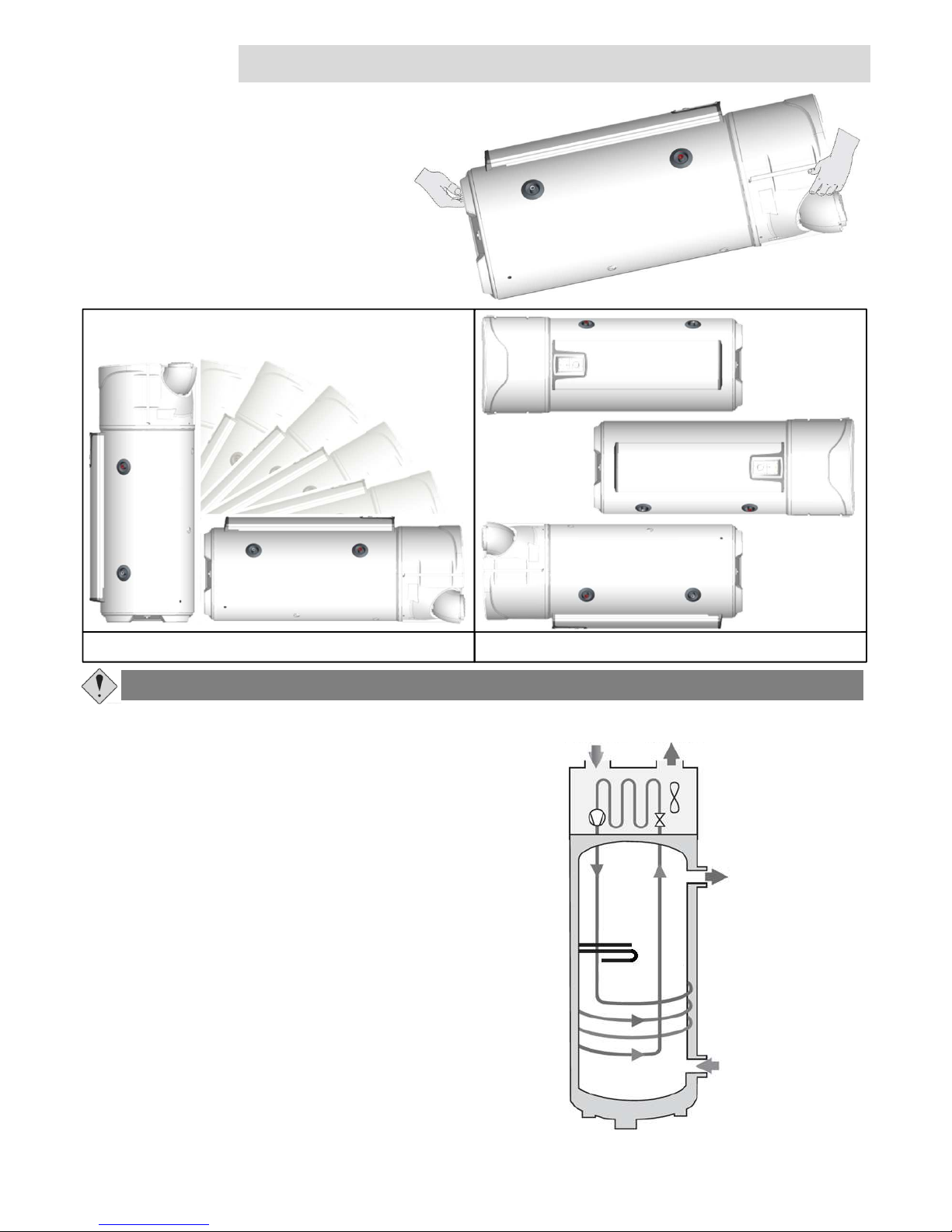
3. Transport
The product integrates several handles to
facilitate handling to the installation site.
To transport the boiler to the installation
site, always use the lower grips and top
handles as shown.
4. Working principles
The heat pump water heater uses unheated air to heat
domestic hot water.
The coolant in the heat pump sets up a thermodynamic
cycle which allows the energy from the unheated ambient
air or the outside air to be transferred to the water in the
cylinder.
The air is passed through the device by a fan, ventilating the
various components including the evaporator.
As it passes through the evaporator, the coolant evaporates
and conveys calories to the intake air.
The compressor compresses the coolant causing its
temperature to rise.
This heat is transmitted by the condenser to the domestic
water stored in the cylinder.
The coolant expands in the thermostatic expansion valve
and cools down. It is then once again ready to receive heat
in the evaporator.
The colder the air, the harder it is to withdraw calories from
it. Similarly, the higher the hot water setting, the harder it is
for the heat pump to return the calories withdrawn
Observe the recommendations and handling on the packaging of the water heater.
☺ Positions accepted Positions forbidden
Air flow
intake
Air flow
exhaust
Hot water
connection
Cold water
connection
5
Page 7
Overview Installation Operation Maintenance Warranty
5. Technical data
Model 200 liters 270 liters
Dimensions ( Height x Width x Depth) mm 1609 x 620 x 665 1949 x 620 x 665
Empty weight (model without coil) kg 85 93
Empty weight (model with coil) kg 100 108
Nominal capacity L 200 270
Hot and cold water connection ¾ ″ M
Coil’s connection 1″ M
Coil’s heating surface m² 1,2
Coil’s power at T
Primary
60°C and flow 1,5m3/h kW 16
Anticorrosion system ACI Hybrid
Rated water pressure Bar 8
Electrical connection (voltage/frequency) - 230V single phase 50 Hz
Maximal total power absorbed by the device W 2465
Maximal power absorbed by the heat pump W 665
Power absorbed by the auxiliary electrical unit W 1800
Heat pump water temperature setting range °C 50 to 62
Heat pump user temperature setting range (air temperature) °C -5 to +43
Duct diameter mm 160
Air flow (without duct) at low speed m3/h 300
Air flow (without duct) at high speed m3/h 390
Load losses acceptable on ventilation circuit, without affecting
performance
Pa 25
Sound power level dB(A) 50,3
Sound pressure level at 2m dB(A) 33,5
R134a refrigerant capacity kg 1,25 1,35
Hot water quantity at 40° : V40td in 8h(Off-peak) L 312 347
Hot water quantity at 40° : V40td in 14h (Off-peak+6h) L 579 607
Performance at 7°C air temperature (EN 16147)
Coefficient of performance (COP) - 2,8 2,9
Tapping cycle - L XL
Standby power input (Pes) W 27 30
Heating up time (th) h.min 7h54 10h41
Reference hot water temperature (T
ref
) °C 54 52,9
Flowrate (air) m
3
/h 305,7 287,6
This device is compliant with directives 2004/108/CEEon electromagnetic compatibility and 2006/95/CEE on low voltage.
6
Page 8

G
Overview Installation Operation Maintenance Warranty
6. Dimensions
Ind MODEL
200
STD
200
ECH
270
STD
270
ECH
A Condensate outlet 1221 1221 1562 1562
B Total height 1609 1609 1949 1949
C Cold water inlet 304 462 304 462
D Hot water outlet 961 961 1300 1300
E Total width 620 620 620 620
F Total depth 665 665 665 665
G
Distance between
air inlet and outlet
418 418 418 418
H Coil inlet - 581 - 581
B
A
D
C
E
F
60°
Dimensions in mm
H
104
7
Page 9
Overview Installation Operation Maintenance Warranty
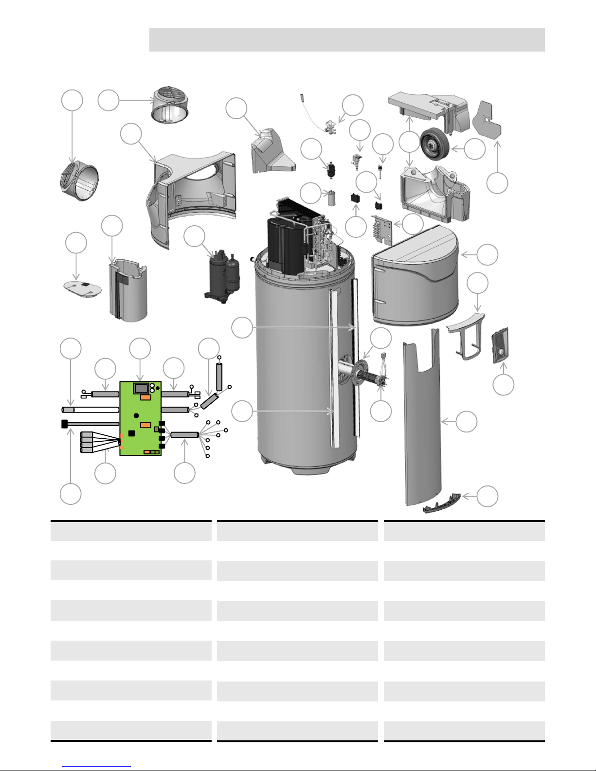
7. Parts list
1
2
3
5
4
6
7
8
9
10
11
12
13
14
15
16
33
18
1
19
18 20
21
22
23
24
1 Adjustable inlet and outlet
2 Rear cover
3 Spoiler
4 Filter
5 Capacitor 15µF
6 TX valve
7 Fan scroll casing
8 Hot gas valve assembly
9 Pressure switch
10 Fan
11 Fan plate support
23 Front column
24 Lower column plug
25 ACI wire
26 Regulation controller PCB
27 Compressor wire
28 Water sensor wire
29 Electrical backup wire
30 Heat pump sensors wire
31 Fan wire
32 Controller wire
33 Compressor jacket cover
12 Capacitor 1,5µF
13 Capacitor 4µF
14 Terminal connection block
15 Front cover
16 Compressor
17 Compressor jacket
18 Guide support rail
19 Hybrid heating sleeve
20 Electrical heating element
21 Controller desk
22 Controller
17
2625
28
30
32
29
27
31
8
Page 10

The device has to be installed on a flat and horizontal floor and
should not be in contact with a wall.
Overview Installation Operation Maintenance Warranty
Installation
Whatever installation configuration is selected the place of installation has to conform to the protection level
IP X1B, complying to the prescriptions of NFC 15-100 ( or local equivalent ).
The floor has to support a load of 400 kg minimum (surface below the water heater).
The non-respect of installation guidelines can cause poor performances of the system.
1. Product installation
The device has to fixed (according article 20 of EN 60335-1) on the ground with the supplied
dedicated metal strap.
It is mandatory to install a retention basin below the water heater if installed above a living area.
License plate placed
over the hot water pipe
has to be easily visible.
Before filling with water
the water heater has to
be levelled.
Fix the water heater
with the supplied
metal strap.
Minimum height from ground to ceiling to
tilt the device :
200L : 1681mm
270L : 2007mm
9
Page 11
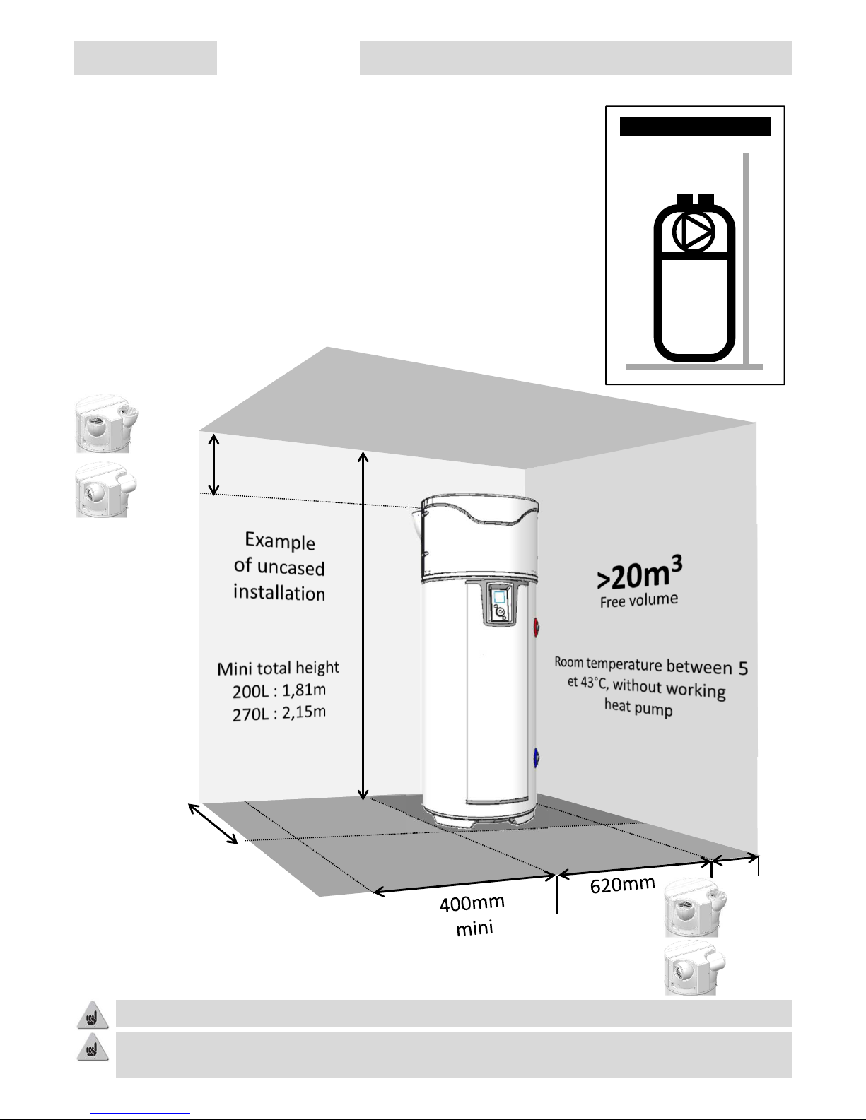
2. Installation uncased (Ambient air).
670mm
mini
Overview Installation Operation Maintenance Warranty
Unheated room with ambient temperature > 5° C and insulate the heated
rooms of the dwelling.
Parameter « Air pipes » to be set on « Inner/Inner »
Recommended room = underground or partially underground, room where
average yearly temperature is > 10° C°.
Keep a free space of 500 mm in front of electric compartment and 300 mm around hydraulic
connections to allow easy access for maintenance.
Examples :
• Garage : recovery of free calories from combustion engine or of domestic
devices.
• Washing room : reduce humidity of the room and recover lost calories of
washing machine and dryer.
It is mandatory to respect indicated distances to prevent air looping .
Inner/Inner
Mini
200mm
Mini
100mm
Mini
200mm
Mini
400mm
10
Page 12
Overview Installation Operation Maintenance Warranty
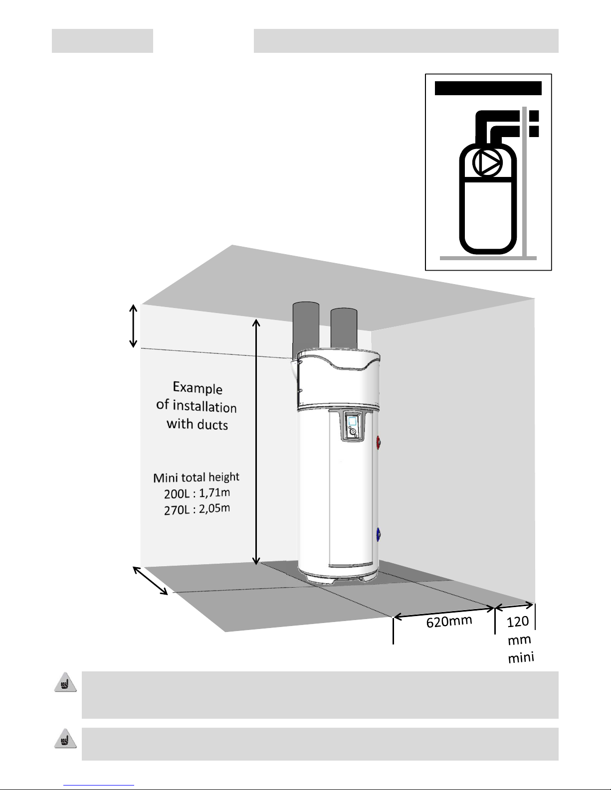
3. Installation cased (2 ducts).
Room at minimum frost free (T > 1°C).
Parameter « Air pipes» to be set « Outer/Outer »
Recommended room : living area (the heat loss of the water heater
remains in heated area), close to external walls. Avoid installation of water
heater and/or ducts near to sleeping rooms.
Examples :
• Washing room,
• Storage room,
• Cupboard in entry area.
670mm
mini
Keep a free space of 500 mm in front of electric compartment and 300 mm around hydraulic
connections to allow easy access for maintenance.
100mm
mini
Respect the maximum length of ducts. Use insulated rigid ducts.
Plan grids at air entry and exit to avoid intrusion of objects or animals.
Attention, entry or exit grids with manual closing device are forbidden.
Outer/Outer
11
Page 13

Overview Installation Operation Maintenance Warranty
4. Installation semi – cased (1 duct for air exit).
non heated room with ambient temperature > 5° C and insulated to the
heated rooms of the dwelling.
Parameter « Air pipes » to be set on « Inner/Outer ».
Recommended room = underground or partially underground, room where
average yearly temperature is > 10° C°.
The pressure reduction in the room generated by the air extraction causes fresh air entry through
doors and windows. Plan an air entry (Ø 160mm) from outside to avoid air sucking from heated
living area.
In winter time the renewed air can cool the room.
Keep a free space of 500 mm in front of electric compartment and 300 mm around hydraulic
connections to allow easy access for maintenance.
670mm
mini
Examples :
• Garage : recovery of free calories from combustion engine or of domestic
devices
• Washing room : reduce humidity of the room and recover lost calories of
washing machine and dryer.
Inner/Outer
12
Page 14

5. Prohibited configurations
Overview Installation Operation Maintenance Warranty
• Water heater extracting air from heated room.
• Connection to a heat recovery ventilation unit.
• Connection of the ducts to the attic.
• Duct on outside air and air exit indoor.
• Connection to an underground air duct.
• Water heater installed in a room together with a boiler connected to a chimney with natural draft and 1
duct to outside.
• Direct air connection to a cloth drying machine.
• Installation in dusty rooms.
• Intake of air with solvents or explosive materials.
• Direct air connection to cooking hoods with polluted and fatty air.
• Installation in a room where freezing temperature can occur.
• Objects stacked on the top of the device.
13
Page 15

6. Hydraulic connection
Overview Installation Operation Maintenance Warranty
Cold water inlet is marked with a blue collar and the hot water outlet has a red collar. Both have a thread gas
dia. 20/27 (3/4").
For regions with a lot of scale (Th>20°f), we recommend to treat the water. The hardness after softener has to
be higher than 15°f. The use of a softener does not influence the warranty if the softener is approved for the
country of installation and set to the rules of art, with regular checking and maintenance.
Local criteria of drinking water quality have to be respected.
The use of a circulation loop should be restrained. Such an installation may disturbs the stratification
inside the tank. This triggers more working cycles for the heat pump and the potential use of the
electric backup heater.
6.1. Cold water connection
Before connection check that the piping is clean without any particles from installation.
The installation has to include a new safety valve set to 7 bar ( 0,7 Mpa ), compliant to EN 1487 and
connected directly on the cold water inlet.
No hydraulic device (stop valve, pressure reduction, flexible...) is allowed between the safety valve
and the cold water inlet of the water heater.
As water can flow from the safety valve the drain
should be kept in open air. In any type of installation
there should be a cold water stop valve, before the
safety valve.
The overflow of the safety valve has to be connected
to the used water evacuation through a siphon.
Installation has to be in a frost-free environment. The
safety valve has to be operated regularly to check the
working condition (1 - 2 times per month).
The installation should be equipped with a pressure
reduction if the main water supply pressure is higher
than 5 bar (0,5 MPa). The pressure reducing device
has to be installed at the beginning of the distribution
network (before the safety valve). We recommend a
supply pressure of 3 - 4 bar (0,3 to 0,4 MPa.
☺ OK ☺ OK
KO
Pressure reduction
Water supply
Safety valve
Cold water
inlet
Siphon
14
Page 16

6.2. Hot water connection
Overview Installation Operation Maintenance Warranty
If the installation is made with synthetic pipes (e.g. : PER, multi-layer…), install mandatory a
thermostatic control valve at the connection pipes of the water heater. The setting should be done in
relation with the specification of the installed piping.
Do not connect copper tubes directly on the tank connection. You have to fit the supplied insulation
union (included in the supply).
In case that the tank connection is corroded without this protection the warranty will not apply.
The use of a siphon to connect to sew water is mandatory (the siphon must not be made with the
supplied tube).
6.5. Condensate evacuation
Depending on the degree of humidity in the air you can get
up to 0,25l/h of condensation. The evacuation of condensate
should not been made directly to sew water because of
possible corrosive gasses damaging the exchanger fins and
water heater parts.
The temperature drop of the air passing through the exchanger forms condensation from humidity
in the air. The condensed water is evacuated on the rear of the tank using the supplied plastic tube.
6.3. Connection of circulation loop
Do not connect copper tubes directly on the tank connection. You have to fit the supplied insulation
union (included in the supply).
In case that the tank connection is corroded without this protection the warranty will not apply.
If the circulation connection is not used install the plug and seal on this connection (included in the
supply).
6.4. Connection of primary circuit (for water heater with coil)
Protect the circuit against over pressure due to water expansion during heating with a safety valve 3
bar – 0,3MPa, or an expansion vessel open type (atmospheric pressure) or a closed expansion vessel.
The nominal circuit pressure should not exceed 3 bar – 0,3MPa, the temperature not higher than
85°C. If the coil is connected to solar panels use an adapted water glycol mix to protect against frost
and corrosion : e.g. « TYFOCOR L ». If the circuit is equipped with stop valves on the coil entry and
exit do never close both valves simultaneously to avoid the risk of over-pressure in the coil.
15
Page 17

7. Air connection
Overview Installation Operation Maintenance Warranty
If the volume of the installation room is not sufficient the water heater can be connected to ducts with a
diameter 160 mm. If the ducts are not insulated this could generate condensation in the ducts during
operation. The use of insulated ducts is mandatory.
If the water heater is ducted the parameter setting has to be adapted.
The total pressure drop of ducts and accessories for air intake and exit has to be less than 150 Pa.
The recommended length of ducts has to be respected.
Position of the air intake and exit.
❶ Unscrew the fixing
screws of the air
connection, then turn in
the required direction.
❸ Rotate again by
120°, position to the
opposite sides.
❷ Rotate by 120°,
position to the rear.
A poor duct installation (duct compressed, length or number of bends too high…) can reduce the
performance. Thus the use of flexible ducts is not recommended.
The ducts can be fitted
directly on the
positionable air in/outlets.
EXIT
Note : The positionable air connections allow to reduce or avoid the duct bends. For further information on the
positionable air connections, see the § « Positioning of the water heater ».
❹ Do not position the
air connection partially
face to face.
Position not allowed as
cold air will be recycled !
☺ ☺
Number of bends 90°
Total duct length with air intake and exit (ATL catalogue)
ALUMINIUM SEMI RIGID PEHD;;;;;;;;;;;;;;
0 8m 19m
1 7m 16m
2 5m 12m
16
Page 18

Overview Installation Operation Maintenance Warranty
8. Electric connection
Refer to the electric connections diagram below and on page 34.
Never supply power directly to the heating element.
The water heater must not be switched on before complete filling with water.
The water heater must be connected to electricity supply permanently.
The water heater has to be connected on single phase 230 V alternative current. Connect the water heater
with a cable with rigid conductors with section of 1,5 mm². The installation is composed of :
• A 16A omni-polar circuit breaker with contacts opening at minimum 3mm,
• A 30mA differential circuit breaker.
If the power cable is damaged, the manufacturer, the after-sales service or similarly qualified people must
replace it, to avoid danger.
The security thermostat fitted to the auxiliary electric heating element must not be repaired in other places
as our factory. Failure to respect this clause invalidates the warranty.
The device must be installed in accordance with the national electrical installation rules.
3x 1,5mm²
16A
Connection to earth is mandatory.
Electric connection diagram
17
Page 19

Overview Installation Operation Maintenance Warranty
9. Connection of optional equipment
Water heaters with a coil can be connected to a gas / fuel oil
boiler. In this configuration, the water heater commands the
heat generation to the boiler.
The connection of the boiler has to be made on the contacts C1
and C2 of the wiring board.
Always switch-off power before any operation.
9.1. Connection to a boiler.
A dedicated cable channel exists for the connections. Please use it.
To access the wiring board read the instructions to remove the front cover.
When associated with a photovoltaic system you can store the
excess energy produced in the water heater as hot water. Once
the photovaltaic panels produce enough energy, the inverter
sends a signal to the water heater which switchs into a special
mode ( PV ) activating the heat pump. If the inverter signal stops,
the water heater switches automatically back to the previous
operating mode. In this PV mode the set temperature is changed
to 62 ° C (no modification possible) and on the display appears
«PV».
The water heaters linked to a photovoltaic installations has to be
connected to the inverter module.
The connection to the inverter is done with B1 and B2 of the
wiring board.
9.2. Connection of a photovoltaic station.
Diagram potential 230V
Diagram dry contact
Electric power supply
Boiler connection
dry contact
A1
A2
B1
B2
C1
C2
Power supply
Photovoltaic connection
contact 230V~
A1
A2
B1
B2
C1
C2
Power supply
Photovoltaic
connection
dry contact
A1
A2
B1
B2
C1
C2
A1
A2
B1
B2
C1
C2
18
Page 20

Overview Installation Operation Maintenance Warranty
Photovoltaic connection: contact 230V
Photovoltaic connection: dry contact
Electricity supplier
Signal 230V~ - 50Hz
Power threshold (mini) = 700W
Inverter PV panels
Signal 230V~ - 50Hz
Available power
Connect
to
B1 B2
Junction
box
Electricity supplier
Signal 230V~ - 50Hz
Power threshold (mini) = 700W
Inverter
PV panels
Dry contact
Available power
Connect
to
B1 B2
Junction
box
19
Page 21

For thermal solar operation the water heater (models with
« solar» exchanger)has to be connected to the solar station. In
this configuration, the water heater receives the signal to operate
the electric backup from the solar station. All other functions are
not active. This connection should not be used for an automatic
multi-energy operation.
The connection to the solar station should be done on the
contacts B1 and B2 of the connection board.
9.3. Connection to a solar station.
Electric power supply
Solar contact 230V~
A1
A2
B1
B2
C1
C2
Overview Installation Operation Maintenance Warranty
9.4. Installation of the solar sensor
Take off the plastic cap and the
foam plug located near the
exchanger connections.
Push the sensor through the
plastic cap (the cap has dedicated
perforations).
Insert the sensor in the sensor
slot and make sure that it is in
correct position in the bottom of
the sensor slot.
Replace the foam plug and clip
the plastic cap.
❶
❷
❸
❹
❺
20
Page 22

Overview Installation Operation Maintenance Warranty
10. Commissioning
10.1. Filling of the tank
Open one or several hot water taps.
Open the cold water tap on the security group (make sure that the drain valve is closed).
When water starts flowing from the hot water taps close them. The tank is full.
Check the connections for possible leaks.
Check the correct function of valves and safety group by opening them several times in order to eliminate
possible particles.
❶
❷
❸
❹
❺
10.2. First operation
Switch on the power supply.
Check that no error message appears on the screen.
At the first switching on the setting instructions are shown on the display. Follow thoroughly the
instructions on the display to set the parameters (Date and time, Air ducts, Installation, circulation loop,
Photovoltaic system, operation range, Anti-legionella system).
When the parameters are set check the functions of the water heater (see § « Checking of operation »).
❶
❷
❸
❹
If the water heater has been tilted wait for minimum 1h before operation.
To return later to the settings, check the paragraphs « Setting of the installation » or « Parameters of
installation ».
Check the information
Follow the instructions
Access to settings
Lock the settings
Navigate - +
Reduce/Increase the values
Return to previous screen
Confirm
MENU
21
Page 23

Overview Installation Operation Maintenance Warranty
10.3. Settings of the installation.
• Date and time
Set the day and confirm. Proceed in the same way for the month, the year, the hour and the minutes.
• Operation time
This parameter defines the allowed working hours for the operation of the heat pump, the electric backup
and, if existing, the hydraulic backup depending on the need of DHW :
Start of the machine any time of the day,
Start of the machine during the programmed period only.
• Connectivity
The Water Heater can be paired with devices using and remotely controlled.
• Language
Setting possible in French, English, Flemish, Spanish, Portuguese, German, Italian et Polish.
• Additional electric backup
Allows to activate or not the use of the electric backup. If not activated, the water heater will never use the
electric backup; in case of low air temperature a lack of hot water is possible.
Access again to the various settings of the installation : +
Permanent 24h/24h
Programming
Settings
10.4. The parameters to set on installation.
(If not set during the first commissioning)
The parameters can be used in MODE INSTALLER
Press and hold the button MENU and rotate the knob a half turn to the
right.
To exit the installer mode, proceed in the same way or wait for
3 minutes.
Access to parameters
Settings
❷
rotate
1/2 turn
to the
right
❶ press and hold
• Air pipes (aeraulics operation) :
This parameter defines the type of aeraulics connection:
Air intake and exit are not connected to air ducts (ambient air)
Air intake and exit are connected to air ducts (fully ducted)
Air exit is connected to an air duct (semi ducted)
• Installation (for models with coil) :
The internal coil is not used
The internal coil is connected to a boiler managed by the water heater
The internal coil is connected to a solar system
In « Connected to boiler» mode , you have to define the degree of priority in the operation of the boiler and
the heat pump in 4 levels :
The backup operates at the end of heating up in case of low air temperature (<7°C)
The backup operates at the end of heating up and ± early depending on air °C
The heat pump works on the start of heating up and stops ± early depending on air °C
The heat pump works on the start of heating up and for air temperature > 10°C.
Thermodynamics only
Connected to boiler
Connected to solar sys.
Inner/Inner
Outer/Outer
Inner/Outer
HP prioritized
HP optimized
Boiler optimized
Boiler prioritized
22
Page 24

Overview Installation Operation Maintenance Warranty
• PV system (Photovoltaic)/Smart-grid :
This parameter activates the pairing of the water heater with a photovoltaic installation. This operating mode
allows the forced start of the heat pump when the photovoltaic inverter sends a signal to the water heater.
The regulation switches automatically to the previous operating mode 30mn after the loss of the photovoltaic
signal.
During the signal reception the set temperature is automatically raised to 62°C (can not be changed).
• Exhaust air :
Allows to activate the air extraction function (2 speed : 300 or 390m3/h). When the water heater does not
heat the tank, the ventilator turns to evacuate the ambient air to the outside (only possible to activate if the
aeraulics connection is set to Indoor/Outdoor).
• Anti-Legionella function :
Allows to activate the function of water disinfection several times per month.
The water temperaturereaches 62°C one to four times per month depending on the setting.
• EMERGENCY-mode :
When activated the water heater operates only on the electric backup heater.
• Circulation cycle:
This mode is mandatory when a circulation loop is installed.
The set temperature changes to 65°C and the operation of the heat pump is adapted to this use.
The heat pump is allowed to work permanently (programming is not available).
10.5. Functional check
Functional check is available in MODE INSTALLER
Press and hold the button MENU and turn the knob half a turn to the
right.
To exit the mode installer, proceed the same way or wait for
10 minutes.
Access to parameters
Test
❷
Rotate
1/2 turn
to the
right
❶ Press and hold
Actuator
Compressor
Start the ventilator then the compressor
Slow operation
Operate the ventilator at low speed
Fast operation
Operate the ventilator at high speed
Defrosting valve Open
Check the click noise of the motor
Compressor + defrosting.
Start the ventilator then the compressor and
click noise of the hot gas valve
Additional electric backup
Start the electric backup heater
Additional boiler
Close the dry contact commanding the
boiler
Temperature sensor
Display the temperatures : incoming air, top
evaporator, bottom evaporator, exit
compressor, hot water
Fan
The TEST menu allows to operate all components of the product.
23
Page 25

Mode MANUAL :
This mode allows to define the desired hot water quantity by selecting the set temperature. The set
temperature is also displayed as equivalence of showers : about 50 L of hot water).
When the mode ECO is not activated, the water heater favors the operation of the heat pump. However if the
air temperature is low or the water consumption high, the electric (or boiler) backup can be used at the end
of the heating cycle to reach the set temperature.
When the mode ECO is activated, the water heater works exclusively with the heat pump in the air
temperature range of -5 to +43°C. The electric backup heater is not used. This function maximizes the energy
savings but can cause a lack of hot water.
Whatever setting of ECO, the electric backup heater is used automatically if the air temperature is outside the
working range to assure a sufficient hot water volume.
Overview Installation Operation Maintenance Warranty
10.6. Choice of operating mode
Press the button to access the menu
Mode
Mode AUTO (only available on installations «heat pump only ») :
This operating mode manages automatically the choice of energy allowing to maximize economies while
supplying a sufficient hot water comfort level.
The water heater analyses the water consumption of the previous days to adapt the hot water production as
required. It reacts to unplanned events by launching working cycles during the day to assure enough hot
water. The set temperature varies automatically between 50 and 62°C according to the consumption profile.
The water heater chooses preferably the heat pump. The electric backup can automatically be added to
provide the correct hot water volume.
10.7. Locking of interface
Press for some seconds to lock/unlock the interface.
Mode MANUAL on installation « Solar backup »
This mode allows the work of the heat pump in combination with a solar backup. However the
simultaneous working of the heat pump and the solar backup can damage the product. The heat
pump must be used in periods when solar energy is not available (to do this use the programming
mode of the water heater)
This mode is not available on installations « boiler backup » and « solar backup »
The mode ECO activated/not activated can’t be changed on installations « Boiler backup »
The mode BOOST : this mode activates the heat pump and all other available energy sources (boiler backup if
set, electric backup) at the same time to reach the maximum set point of 62°C.
The mode ABSENCE : this mode maintains the hot water temperature above 15°C by using the heat pump.
The boiler and electric backup can be used if the heat pump is not available.
24
Page 26

Overview Installation Operation Maintenance Warranty
Operation
1. Interface.
Display the information
Follow the instructions
Access to settings
Lock the settings
Navigate - +
Reduce/Increase the values
Return to previous screen
Confirm
2. Description of pictograms.
Fast heating confirmed
Absence registered / in operation
Present hot water temperature
Waiting
Warning
Electric backup working
Heat pump working
Boiler backup working
Reception of signal on solar system
contact
Reception of signal on photovoltaic
/ Smart-grid contact
MENU
25
Page 27

Overview Installation Operation Maintenance Warranty
3. Main menu.
Access to
settings
Follow instructions
displayed on screen
Navigate in the MENU
Reduce the
values
OK
Confirm
Increase
the values
Increase the hot water production during the period :
Set the number of days BOOST should work (from 1 to 7).
At the end of the set period, the water heater resumes the initial operating mode.
BOOST can be stopped at any moment :
Stop BOOST
Choose the operating mode:
Select AUTO or MANUAL (see § « The operating modes »
Program absence period:
Allows to indicate the water heater
• a permanent absence starting from the present day.
• a programmed absence (set the starting date and the return date). The day before return
a anti-legionella heating cycle starts.
During the absence period, the water temperature remains above 15°C.
This function can be interrupted at any moment:
Stop absence
Display the energy savings :
Allows to display the working level of the heat pump and of the electric backup during the
last 7 days, the last 12 months, since commissioning.
Display the electric consumption :
Allows to display the energy consumption in kw/h, of the last days, the last months, the
last years.
Display the parameters :
Allows to display the registered settings.
Set the date and time :
Set the day and confirm. Set the month, the year, the hour and the minutes.
Set the periods of operation :
Allows to define periods when the water heater may start.
Connectivity :
The Water Heater can be paired with devices using and remotely controlled.
Set the language :
French, English, Dutch, Spanish, Portuguese, German, Italian and Polish.
Additional Electric backup heater :
Allows to deactivate the use of the electric backup heater.
26
Page 28

SMART Energy Function :
A heat pump uses the available energy in the air and
transfers this energy through an exchanger around
the tank to the water. The heat pump performance is
higher when the exchange parameters are more
favorable; i.e. air temperature higher or tank
temperature lower. Our regulation evaluates
permanently the air and water temperature and what
energy source is more economical. The function
SMART Energy can decide to start heating with the
heat pump and to finish heating up with the boiler
backup.
-5 0 5 10 15 20 25 30 35 40 43
62
T°water
T°air
Priority HPOptimize
HP
Optimize
boiler
Priority
boiler
Overview Installation Operation Maintenance Warranty
4. The operating modes.
AUTO: The set temperature varies automatically between 50 and 62°C according to the consumption profile.
The water heater chooses preferably the heat pump. The electric backup can automatically be added to
provide the correct hot water volume.
MANUAL – ECO Not activated: The set temperature is fixed by the user between 50 and 62°C. The water
heater chooses preferably the heat pump. The electric backup can automatically be added to provide the
correct hot water volume.
MANUAL – ECO Activated: The set temperature is fixed by the user between 50 and 62°C. The water heater
chooses preferably the heat pump to maximize the energy savings. The electric backup is allowed to work if
the air temperature is out of the operating range.
4.1 The installation mode « Heat pump only » :
MANUAL : The set temperature is fixed by the user between 50 and 62°C. The water heater chooses
preferably the heat pump. The boiler backup can be activated automatically to provide the correct hot water
volume. If the backup through the boiler is not available (e.g. boiler switched off), the electric backup will be
activated.
4.2 The installation mode « Boiler backup » :
The water heater works only during the period when the solar system does not supply energy (when the solar
system signal is off). During the periods of solar production, the hot water production is operated with the
internal coil, the heat pump and the electric backup are not working.
MANUAL – ECO Not activated : The set temperature is fixed by the user between 50 and 62°C. The water
heater chooses preferably the heat pump. The electric backup can automatically be added to provide the
correct hot water volume.
MANUAL – ECO Activated : The set temperature is fixed by the user between 50 and 62°C. The water heater
chooses preferably the heat pump to maximize the energy savings. The electric backup is allowed to work if
the air temperature is out of the operating range.
4.3 The installation mode « Solar backup » :
The electric backup will never work if the parameter « Electric backup » is deactivated.
The Smart Energy function can be set on 4 different management levels:
The backup operates at the end of heating up in case of low air temperature (<7°C)
The backup operates at the end of heating up and ± early depending on air °C
The heat pump works on the start of heating up and stops ± early depending on air °C
The heat pump works on the start of heating up and for air temperature > 10°C.
60
55
50
45
40
30
35
25
20
15
Heat
pump
Boiler
HP prioritized
HP optimized
Boiler optimized
Boiler prioritized
27
Page 29

Overview Installation Operation
Service, Maintenance and Repair
If the absence mode cannot be used it could be necessary to drain the water heater if the device is switched
off. Proceed as follows:
1. Advice to the user.
The device has to be disconnected from mains before opening the cover.
Maintenance Warranty
Switch off power supply.
Open a hot water tap.
Close the cold water inlet.
Open the drain valve on the
security group.
❶
❸
❷
❹
In order to maintain the performances of your water heater, we advice to service it regularly.
2. Service.
By the USER :
What When How
Security group 1 to 2 times per month Operate the safety valve.
Check that water evacuation is ok.
General 1 time per month Check external shape of your device : no Error code
displayed, no leakage on the connections...
By the INSTALLER :
What When How
Ducts 1 per year Check if the device is ducted.
Check if the ducts are well positioned and not
deformed.
Condensates evacuation 1 per year Check the cleanness of the condensates evacuation
tube.
Electric connections 1 per year Check that any internal and external cable connections
are not loose and that all connectors are plugged in.
Electric backup 1 per year Check the correct function of the electric backup by
measuring the power.
Scaling Every 2 years If the supply water is hard clean the deposited scale.
28
Page 30

To access to the heat pump
compartment :
Remove 4 screws on the front,
Tilt the hood to the front.
Overview Installation Operation Maintenance Warranty
Only a refrigeration engineer is permitted to have access to the expansion valve adjustment screw.
If the expansion valve is adjusted without approval from the constructor, the product warranty may
be invalidated.
it is not recommended to touch the expansion valve setting until all other repair solutions have been
exhausted.
What When How
Thermal exchange of the
heat pump
Every 2 years* Check the correct working of the heat pump.
Components of the heat
pump
Every 2 years* Check the ventilator operation on it’s 2 speeds and the
hot gas valve.
Evaporator Every 2 years* Clean the evaporator with a nylon brush and products
neither scratching nor corrosive.
Refrigerant Every 5 years* Check the refrigerant quantity.
By the REFRIGERATION ENGINEER :
3. Open the water heater for maintenance.
❶
❷
❶ ❷
* In case of dusty environment increase the maintenance frequency.
To access the regulation:
Remove the clipped bottom plug of the front column,
Unscrew the 2 screws on each side of the column,
Slide the column down for 10 centimeters to liberate the interface support,
Press the center of the column to open and remove from the guiding rails.
❶
❷
❸
❹
❶ ❸❷ ❹
29
Page 31

Overview Installation Operation Maintenance Warranty
If there is a problem, lack of heating or release of fumes from the water outlet, cut the power supply and
notify your installer.
4. Trouble shooting.
Displayed Code Reason Result Service action
Error 03
Water temperature
probe defect or out
of measuring range
Reading of water
temperature
impossible : no
heating up.
Check the connection (A1) of the probe
(immersion sleeve).
If required replace the probe.
Error 07
No water in the tank
or ACI connection
open
No heating up
Fill the tank with water.
Check the connection (AC) of the cables, the
water conductivity.
Error 09
Water temperature
too hot (T>80°C)
Risk to trigger the
mechanical security
thermostat : no
heating up
Check the real temperature at a tap (T>80°C).
Check the connection (A1) and the position of
the temperature probe (immersion sleeve).
Check that the electrical backup is not
working permanently. Reset the mechanical
security device if necessary.
Water too cold
Cold water
temperature too
cold(T<5°C)
HP stopped.
Heating with electric
backup.
Resetting automatically at T>10°C. Control the
situation of the installation room (frost-free).
Error 21
Air intake probe
defect or out of
measuring range
HP stopped.
Heating with electric
backup.
Check the connections (A4) and the position
of the air intake probe. If necessary replace
the probe cable harness.
Error 22
Evaporatortop
probe defect or out
of measurement
range (-20 to 110)
HP stopped.
Heating with electric
backup.
Check the connections (A4) and the correct
contact of the probe to the tube.
Check the operation of the ventilator and that
it turns easily without any stop.
Error 23
Evaporator bottom
probe defect or out
of measurement
range (-20 à 110)
HP stopped.
Heating with electric
backup.
Check the connections (A4) and the correct
contact of the probe to the tube.
Check the operation of the ventilator and that
it turns easily without any stop.
Error 25
Pressure switch open
or compressor
thermal safety
HP stopped.
Heating with electric
backup.
Check the compressor connections (R1),
pressure switch, starting capacitor (15mF) and
the hot gas valve (T2). Control the resistance
of compressor windings.
Repairs have to be done exclusively by a qualified installer.
4.1. Error codes.
The alarm can be paused or reset by pressing OK.
30
Page 32

Displayed Code Reason Result Service action
Error 27
Compressor
probe defect or
short circuit
HP stopped.
Heating with
electric backup.
Check the connections (A4) and the position of the
compressor probe. If necessary replace the probe
harness.
Error 28
Default on
defrosting
HP stopped.
Heating with
electric backup.
Check the cleanness of the evaporator.
Check the refrigerant R134a charge (defrosted).
Check the operation of the ventilator.
Check the correct evacuation of condensates.
Check the hot gas valve connections (T2) and it’s
function (TEST menu).
Error 29
Flow temperature
of the
compressor too
high
HP stopped.
Heating with
electric backup.
Control the resistance of compressor windings.
Check the cleanness of the evaporator.
Check the refrigerant R134a charge.
Check that the air circulates without any obstacles.
Error 30
HP operates
without stop
more than 24h or
lack of power.
HP stopped.
Heating with
electric backup.
Check the cleanness of the evaporator.
High consumption or circulation loop or leak on hot
water circuit.
Check the connections (A4) and the correct contact
of the probes to the tubes.
Check the charge, the overheat value (5 minimum),
the defrost operation…
Control the resistance of compressor windings.
Overview Installation Operation Maintenance Warranty
Default Possible reason Diagnosis and service
Water not hot enough. Power supply is not permanent.
Set temperature too low.
Mode ECO selected & air
temperature out of range.
Electric backup or supply cables
(partially) defect.
Check that the device receives
permanently electric current.
Check that no cold water flows into
the hot water circuit (mixing tap
defect).
Select a higher set temperature.
Select the mode AUTO. Check the
periods of programming.
Check the resistance of the heating
element on the plug, and the good
shape of the cables.
Check the security thermostat.
4.2. Other failures without error code display.
31
Page 33

Default Possible reason Diagnosis and service
No heating
No hot water
No power supply to the water
heater : fuse, cabling…
Check the voltage on the power
supply cable
Check the parameters of the
installation (see periods of
operating)
Hot water volume not sufficient Water heater layout too small
Operation in ECO mode
Check the programmed periods
and reception of Night / Low Tariff
signal.
Select AUTO mode
Low pressure on the tab. Filter of security group clogged.
Tank full of scale.
Clean the filter (see §
maintenance).
Remove the scale from the tank.
Water dripping out of the security
group when the water heater is not
heating
Security group damaged or
clogged.
Supply pressure too high
Replace the security group
Check that the supply pressure
after the water counter does not
exceed 5 bar (0,5 MPa), if it does
install a pressure reducer set to 3
bar (0,3 MPa) at the start of the
water network.
The electric backup heater does not
work.
Mechanical security thermostat
was triggered.
Thermostat defect
Backup heater defect.
Reset the security thermostat on
the heating element.
Replacer the thermostat
Replace the element
Condensate overflow. Condensates evacuation clogged Clean the evacuation
Bad smell No siphon installed on the security
group or on condensates
evacuation
No water in the siphon of the
security group
Install a siphon
Fill the siphon
Vapor on the hot water tap Electric backup works permanently Shut off the electricity supply and
call the installer.
Interface does not work or display
problems
No power supply
Interface defect
Control the power supply.
Replace interface.
Overview Installation Operation Maintenance Warranty
After maintenance or repair, check the correct operating of the water heater.
32
Page 34

Overview Installation Operation Maintenance Warranty
Warranty
The following faults are excluded from this warranty: :
• Abnormal environmental conditions::
• Various damage caused by impact or dropping during handling after leaving the factory..
• Placing the appliance in a place exposed to frost or bad weather (damp, aggressive or poorly
ventilated environments).
• Use of water with aggressiveness criteria as defined by DTU Plumbing 60 - 1 additive 4 hot water
(chlorine rate, sulfates, calcium, resistivity and total alkali level)..
• Water with Th < 15° f.
• Water pressure higher than 5 bar (0,5 MPa).
• Electrical power with significant voltage spikes (mains, lightning, etc.).
• Damage from undetectable problems caused by choice of location (places difficult to access) and
that could have been avoided if the appliance were repaired immediately.
• Installation does not comply with regulations, standards, professional rules, especially:
• Safety unit distant or rendered inoperative (pressure reducing valve, non return valve or valve, ...,
placed upstream of the safety group).
• Missing or incorrectly fitted new safety unit NF-D 36-401 or equivalent, modification of calibration,
etc. …
• Missing dielectric union (cast iron, steel or insulating) on hot water connection pipes, leading to
their corrosion.
• Faulty electrical connection ( NF C 15-100 or equivalent ): incorrect grounding, inadequate cable
section, connection of flexible cables without metal terminations, failure to respect connection
diagrams specified by the Manufacturer.
• Powering up the appliance without first filling it (dry heating).
• Placing the appliance without consideration of manual instructions.
• External corrosion caused by poor sealing on pipes.
• Installation of a circulation loop.
• Wrong parameter setting for a ducted installation.
• Duct configuration not compliant to our instructions.
• Faulty maintenance: :
• Abnormal scaling of heating elements or safety units.
• No maintenance of safety unit, leading to excess pressure.
• No cleaning of evaporator or condensate evacuation.
• Modification of original equipment, without notifying constructor, or use of spare parts not
recommended by manufacturer.
1. Scope of warranty application.
A device being allegedly the origin of a damage has to remain on the place of installation for an
expert visit, the person supporting the damage has to inform his insurance.
33
Page 35

2. Warranty conditions.
Overview Installation Operation Maintenance Warranty
The water heater must be installed by a person qualified to professional standards, in accordance with
standards in force and the conditions of our technical departments..
It will be used in the normal way, and regularly maintained by a specialist.
Under these conditions, our warranty is implemented by free exchange or supply to our distributor or installer
of parts acknowledged as faulty by our departments, or of the whole appliance if necessary, excluding labor
costs, transport charges and any compensation for warranty extension.
Our warranty takes effect from the date of purchase (according to invoice), and where there is no
documentary evidence, the date used will be that of manufacture as shown on the water heater information
plate, plus six months.
The warranty on the replacement part or water heater (under warranty) ends at the same time as the part or
water heater replaced.
N.B.: Costs or damages caused by a faulty installation (freezing, safety unit not connected to waste water
discharge, no holding tank, for instance) or problems with access cannot in any case be blamed on the
manufacturer.
The provisions of this warranty do not exclude the purchaser's enjoyment of the legal warranty against
defects and hidden faults, that apply in all cases under the terms of articles 1641 ff of the French Civil Code.
The supply of spare parts necessary for the use of our products will be assured for 7 years after the
production of the last unit.
APPLIANCE END OF LIFETIME:
• Before dismantling shut off power supply and drain the tank.
• The combustion of some components can liberate toxic gas, do not burn the appliance.
• At the end of lifetime the appliance has to be collected by a sorting center for electric and
electronic devices equipped for the refrigerant reclaiming. To learn more about existing recycling
centers, contact the local recycling organizations.
• The enclosed refrigerant must not be liberated into the atmosphere. Any degassing operation is
formally prohibited.
The GWP (Global Warming Potential) of R134a is 1430.
Failure of a component does not in any case justify replacement of the appliance. Replace the faulty
part.
WARRANTY :
Water heater : 5 years (tank tightness, electronic PCB, electric backup and probes).
Heat pump : 2 years (except probes : 5 years).
34
Page 36

1
2
3
4
5
6
7
8
910
11
12
13
14
15
16
17
18
19
20
21
22
1
Probe oulet pipe of compressor
2 Probe supply air
3 Probe evaporator top
4 Probe evaporator bottom
5 Evaporator
6 Ventilator
7 Capacitor ventilator start
8 Capacitor small speed ventilator
17 Controller
18 Regulation PCB
19 Customer wiring board
20
Permanent power supply cable
Not supplied :
21 Connection cable PV / Smart Grid / Solar
22 Connection cable boiler
9
Compressor connections
10 Compressor overheat protection
11 Pressostat
12 Capacitor compressor start
13 Hot gas valve motor
14 Electric backup heater
15 Immersion sleeve water probe
16 Security thermostat
ELECTRIC DIAGRAM
35
Page 37

Page 38

Page 39

Page 40

U05xxxxx_B – Mars 2016
 Loading...