

Page 1

1
GCS1642/GCS1644
PART NO. M1087-b / M1088-b
User Manual
2/4-Port Dual View Dual Link DVI KVMP Switch with Audio
GCS1642/GCS1644
PART NO. M1087-b / M1088-b
Page 2

2
Page 3

3
Table of Contents
Package Contents 4
System Requirements 5
GCS1642 Overview 6
GCS1644 Overview 8
Single Stage Installation 10
Quad View (DDC Mode) 15
LED Indication 17
Port Switching 18
Port Switching via Hotkeys 19
Auto Scanning 21
Hotkey Setting Mode (HSM) 22
Mac Keyboard Emulation 24
Sun Keyboard Emulation 25
Factory Default Hotkeys Settings 26
Firmware Upgrade 27
Upgrade Fail 32
Federal Communications Commission
(FCC) Statement
33
CE Statement 34
Limited Warranty 35
Contact 36
Page 4

4
Package Contents
– 1 x 2/4-Port Dual View Dual Link DVI KVMP Switch with Audio
– 2/4 x Dual Link DVI KVM Cables (2 for GCS1642 / 4 for GCS1644)
– 2/4 x Dual Link DVI Cables (2 for GCS1642 / 4 for GCS1644)
– 1 x USB to PS/2 Converter
– 1 x Power Adapter
– 1 x Installation Guide
– 1 x Warranty Card
Page 5

5
System Requirements
Console
– Two displays with DVI inputs
– A Keyboard and Mouse
Computer
– Computers with DVI outputs
– An open USB port
Optional Audio
– Analog audio connections for speakers and mic.
Page 6
GCS1642
Dual Link Dual View
DVI KVMP SWITCH
6
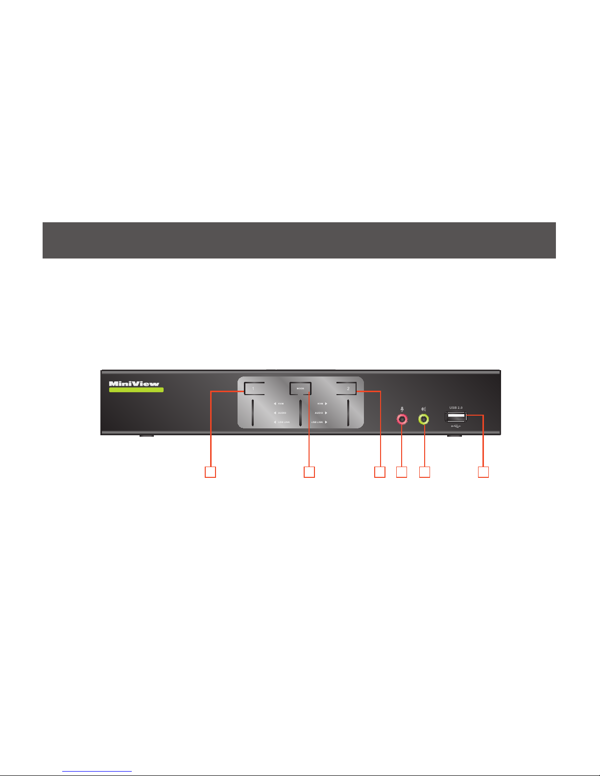
GCS1642 Overview
Front View
1. Port 1 Pushbutton
2. Mode Button
3. Port 2 Pushbutton
4. Front Panel Console Mic. Connection
5. Front Panel Console Audio connection
6. Front Panel USB 2.0 Peripheral Sharing Port
32 4 5
1
6
Page 7
7
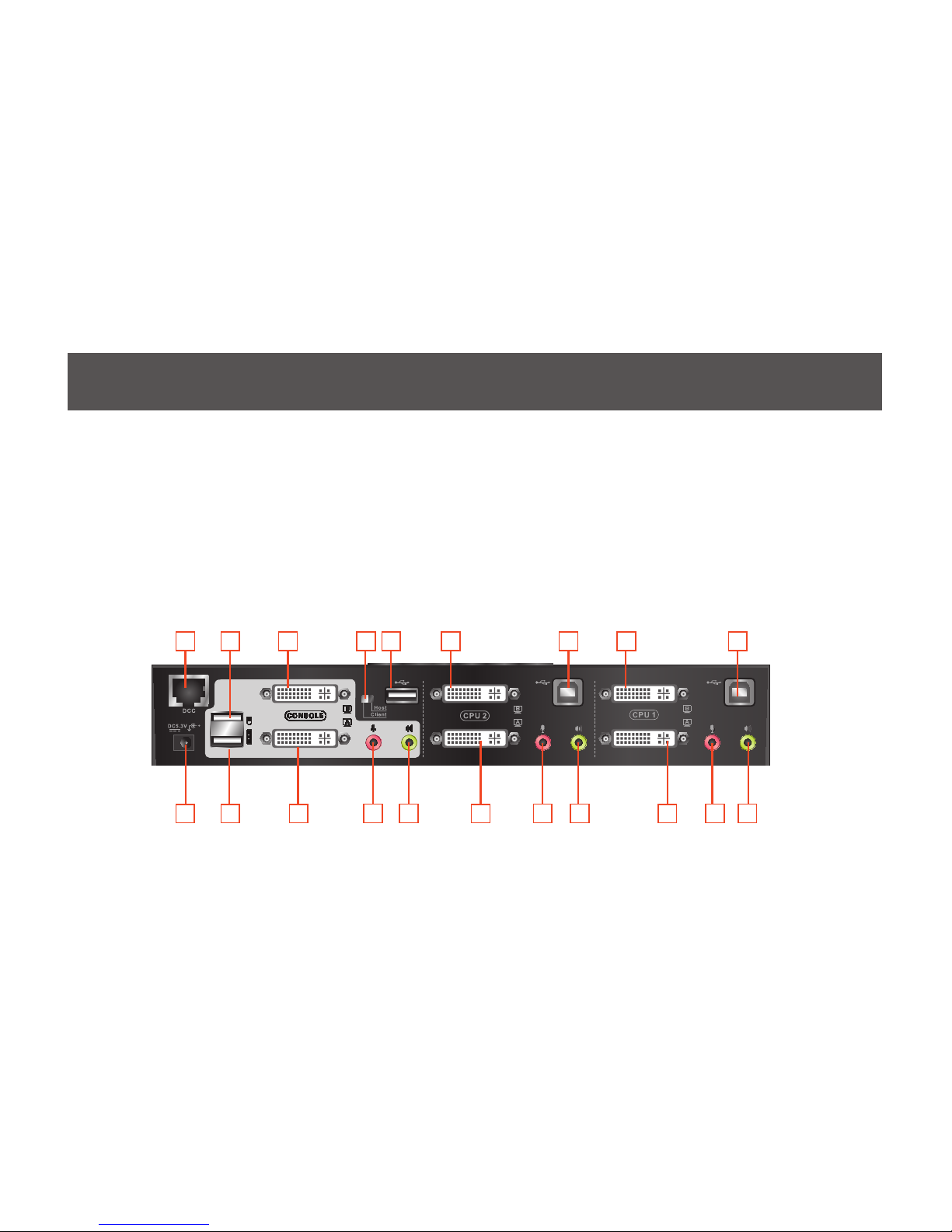
Rear View
14 19
10
15 20
6
9
4
12 17
2
31 5 7
1. DDC Port (Daisy Chain Port)
2. DC Power Jack
3. Console USB Mouse Port
4. Console USB Keyboard Port
5. Console DVI Video Port B
6. Console DVI Video Port A
7. DDC Switch (Host/Client)
8. USB 2.0 Peripheral Sharing Port
9. Console Mic. Connection
10. Console Audio Connection
11. CPU2 DVI Video Port 2B
12. CPU2 DVI Video Port 2A
13. CPU2 USB Connection
14. CPU2 Mic. Connection
15. CPU2 Audio Connection
16. CPU1 DVI Video Port 1B
17. CPU1 DVI Video Port 1A
18. CPU1 USB Connection
19. CPU1 Mic. Connection
20. CPU1 Audio Connection
8
11 16 1813
Page 8
GCS1644
Dual Link Dual View
DVI KVMP SWITCH
8
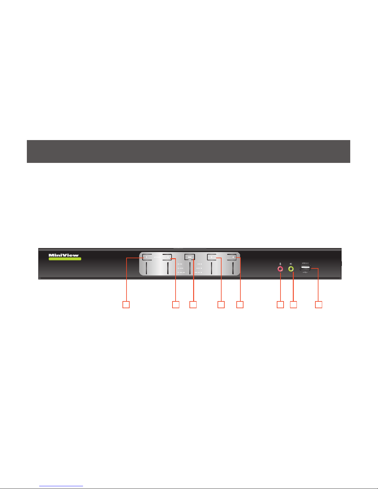
GCS1644 Overview
Front View
2 43 5 6 7
1
1. Port 1 Pushbutton
2. Port 2 Pushbutton
3. Mode Button
4. Port 3 Pushbutton
5. Port 4 Pushbutton
6. Front Panel Console Mic. Connection
7. Front Panel Console Audio connection
8. Front Panel USB 2.0 Peripheral Sharing Port
8
Page 9
9
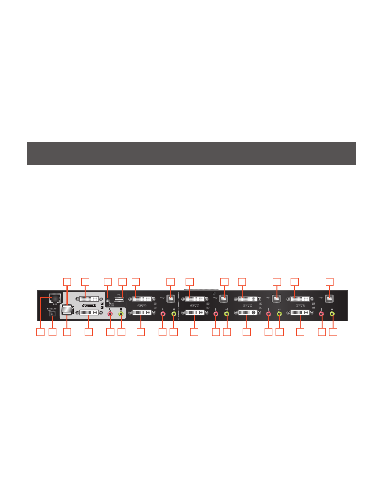
Rear View
1. DDC Port (Daisy Chain Port)
2. DC Power Jack
3. Console USB Mouse Port
4. Console USB Keyboard Port
5. Console DVI Video Port B
6. Console DVI Video Port A
7. DDC Switch (Host/Client)
8. USB 2.0 Peripheral Sharing Port
9. Console Mic. Connection
10. Console Audio Connection
11. CPU4 DVI Video Port 4B
12. CPU4 DVI Video Port 4A
13. CPU4 USB Connection
14. CPU4 Mic. Connection
15. CPU4 Audio Connection
16. CPU3 DVI Video Port 3B
17. CPU3 DVI Video Port 3A
18. CPU3 USB Connection
19. CPU3 Mic. Connection
20. CPU3 Audio Connection
21. CPU2 DVI Video Port 2B
22. CPU2 DVI Video Port 2A
23. CPU2 USB Connection
24. CPU2 Mic. Connection
25. CPU2 Audio Connection
26. CPU1 DVI Video Port 1B
27. CPU1 DVI Video Port 1A
28. CPU1 USB Connection
29. CPU1 Mic. Connection
30. CPU1 Audio Connection
1 2 4 6 12 17 22 279 14 19 24 2910 15 20 25 30
3 5 11 16 21 267 8 13 18 23 28
Page 10
10
Single Stage Installation
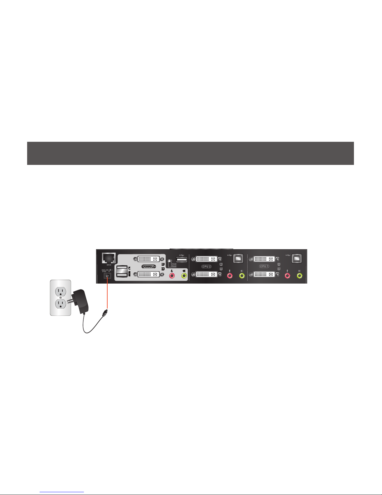
Step 1
Please make sure your source devices and display are powered off before you start.
Step 2
Plug the power adapter into the power outlet and connect it to the DC power jack from the KVM.
Page 11
11
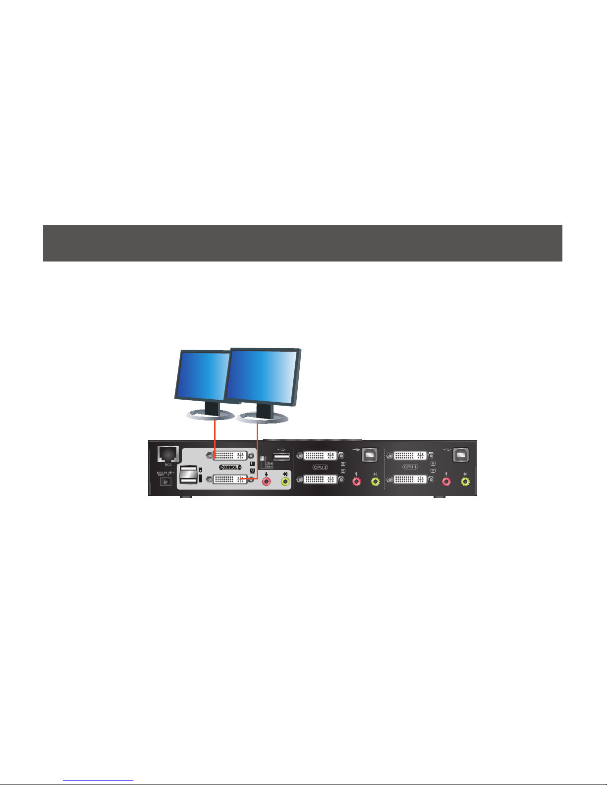
Step 3
Connect the DVI cables from your monitors to the console DVI port A and B. Port A will be your main
monitor and Port B will be your extended desktop monitor.
Page 12
12
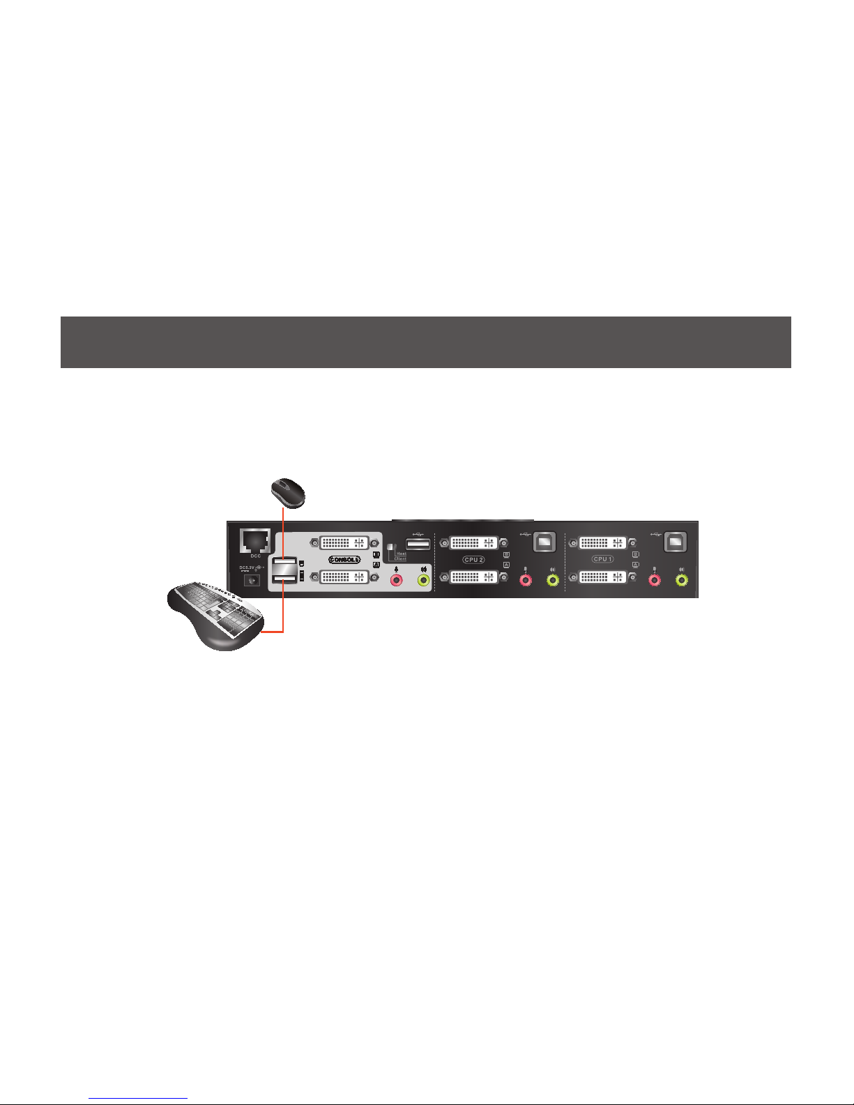
Step 4
Connect your USB keyboard and mouse to the console USB keyboard port and console USB mouse
port.
Note: If you are using PS/2 keyboard and mouse, please use the included PS/2 to USB converter. Simply
connect the PS/2 keyboard and mouse to the PS/2 keyboard and mouse port from the converter, then
connect the USB port to the console USB keyboard port.
Page 13

13
Step 5
Connect a set of your Dual Link DVI KVM cable from the KVM switch to each of your computers – DVI
connection from DVI Port A to the DVI output and USB connection to open USB port from your computer.
Connect the audio and mic. connectors to your audio output and mic. input.
Page 14

14
Step 6
Connect Dual Link DVI cables from DVI Port B of the KVM to your second DVI output of your computers.
Final Step
Turn on your source devices.
Page 15

To expand your installation from Dual View displays to Quad view displays, you can use the DDC Mode
port to connect two GCS1642 / GCS1644 units together. After doing so, you will be able to congure the
quad displays video settings on the computer in extended mode or Mirrored mode.
To set up DDC mode, power off all devices, refer to the installation diagram on the next page.
1. Connect all the computers to the Host as described in Hardware Setup, Cable Connection on page 18.
2. On the Client, using two custom DVI Dual Link cables, plug the DVI connectors into the DVI sockets A
and B in the same KVM port section of the switch.
3. At the other end of the two custom DVI Dual Link cables, plug the monitor cable into the respective
ports on the computer.
4. Repeat steps 2 and 3 for all computers.
5. On the rear of the second GCS1644, set the DCC switch to Client.*
6. On the rear of the primary GCS1644, set the DCC switch to Host.
7. Plug the console monitors into the DVI console ports located on the Host’s and Client’s rear panel.
8. Using an RJ-45 cable, connect the DCC port of the Host to the DCC port of the Client.
9. Power up the installation: plug in the power cord for the Host and Client, then power on both. After
both units are up, power on the computer/video source devices.
Note:
1. In DCC mode the Client’s front panel pushbuttons are disabled and it takes all commands directly from the Host.
2. Setting the DCC switch to Client will disable all front panel pushbuttons on that switch.
15
Quad View (DDC Mode)
Page 16

16
Page 17

17
LED Indication
LED Description
Mode Orange Shows the pushbutton mode that the KVM is in
Online / Selected Dim Green A device is connected to the KVMP switch but the port is
not on focus
Bright Green The specic port has focus on the KVM (Keyboard, video
and mouse)
Audio Green The specic port has focus on the audio
USB Link Green The specic port has focus on the USB peripheral sharing
ports
Page 18

Simply press the front panel Pushbutton from the multimedia KVMP switch or trigger hotkeys from your
keyboard.
Port Switching via Front Panel Pushbutton
Function Description
Switch all focus (KVM, audio and USB)
to a specic port
Press the correspond push button once for the desire port
that you wish to switch focus to.
Switch KVM focus to a specic port Press the Mode button once (Orange LED will show you
are in KVM Mode), then press the correspond push button
for the desire port that you wish to switch focus to.
Switch audio focus to a specic port Press the Mode button twice (Orange LED will show you
are in Audio Mode), then press the correspond push button
for the desire port that you wish to switch focus to.
Switch USB focus to a specic port Press the Mode button three times (Orange LED will show
you are in USB Mode), then press the correspond push
button for the desire port that you wish to switch focus to.
18
Port Switching
Page 19

Port Switching via Hotkeys
Hotkeys Description
[Scroll Lock] [Scroll Lock] [Enter] Switch all focus (KVM, audio and USB) to the next
port
[Scroll Lock] [Scroll Lock] [n] [Enter] Switch all focus (KVM, audio and USB) to port n*
[Scroll Lock] [Scroll Lock] [k] [Enter] Switch KVM focus to the next port
[Scroll Lock] [Scroll Lock] [n] [k] [Enter] Switch KVM focus to port n*
[Scroll Lock] [Scroll Lock] [s] [Enter] Switch audio focus to the next port
[Scroll Lock] [Scroll Lock] [n] [s] [Enter] Switch audio focus to port n*
[Scroll Lock] [Scroll Lock] [u] [Enter] Switch USB focus to the next port
[Scroll Lock] [Scroll Lock] [n] [u] [Enter] Switch USB focus to port n*
Continue next page
19
Port Switching via Hotkeys
Page 20

[Scroll Lock] [Scroll Lock] [n] [k] [u] [Enter] Switch KVM and USB focus to port n*
[Scroll Lock] [Scroll Lock] [n] [k] [s] [Enter] Switch KVM and audio focus to port n*
[Scroll Lock] [Scroll Lock] [n] [u] [s] [Enter] Switch USB and audio focus to port n*
Port Switching via Hotkeys
*Note: n is an interval that stands for the Port number
k stands for KVM focus
s stands for audio focus
u stands for USB focus
20
Page 21

*Note: Autoscan Mode from front panel push button will be scanning a port every 5 seconds by default. If you
wish to have the Autoscan Mode be scanning with different time interval, please refer to trigger Autoscan Mode
from hotkeys.
**Note: n is an interval between 1 and 99 that stands for the time (in second) desire for scanning each port.
You can either activate Autoscan Mode via front panel push button or hotkeys.
Function Description
Auto Scan
Front panel
pushbutton
Press and hold port 1 and port 2 Pushbutton simultaneously for 2
seconds to activate Autoscan Mode*
Hotkeys
[Scroll Lock] [Scroll Lock]
[a] [Enter]
Activate Autoscan mode. It will cycle from
port to port every 5 seconds (default)
[Scroll Lock] [Scroll Lock]
[a] [n] [Enter]
Activate Autoscan mode. It will cycle from
port to port every n seconds**
21
Auto Scanning
Page 22

Hotkey Description
1. Press and hold [Num Lock]
([Clear] key on Mac keyboard)
2. Press and release [-]
3. Release [Num Lock] ([Clear]
key on Mac keyboard)
Invoking hotkey setting mode
Invoke HSM, then press [h] Change the HSM invocation keys from [Num Lock] to [Ctrl] and
from [-] to [F12]
Invoke HSM, then press [t] Switch port switching hotkey sequence between [Scroll Lock]
[Scroll Lock] and [Ctrl] [Ctrl]
Invoke HSM, then press [F2] Enables Mac keyboard emulation
Invoke HSM, then press [F3] Enables Sun keyboard emulation
Invoke HSM, then press [F10] Auto-detect the keyboard operating platform (for PC compatible
systems). Activates Pass Through Keyboard Mode (keystrokes are
sent directly to the computer instead of through the Mac emulator).
Invoke HSM, then press [F4] Open a text editor such as notepad and the information will be
displayed after use the hotkey shown to the left.
22
Hotkey Setting Mode (HSM)
Page 23

Invoke HSM, then press [F5] USB Reset
Invoke HSM, then press [b] Toggle hotkey beepers on or off
Invoke HSM, then press [x] [Enter] Disable or enable port switching hotkey
Invoke HSM, then press [u] [p] [g]
[r] [a] [d] [e] [Enter]
Activate Firmware Upgrade Mode – Front panel KVM LED will ash
indicating Firmware Upgrade Mode is activated.
Invoke HSM, then press [r] [Enter] Restore default KVM settings
Invoke HSM, then press [d] Capture and store video information on specic port
Invoke HSM, then press [m] Enable or disable mouse emulation
Invoke HSM, then press [F1] Reset keyboard and mouse under some special OS’ that do not
support USB 2.0
Invoke HSM, then press [n] Toggles keyboard emulation on/off (default is on)
Invoke HSM, then press [w] Toggles mouse port switching on/off. To use this function, mouse
emulation must be enabled
Invoke HSM, then press [c] Changes front panel push buttons to a hotkey of your choice
(GCS1644 only)
*Note: To exit HSM manually, press Esc or spacebar
23
Page 24

24
Mac Keyboard Emulation
PC Keyboard Mac Keyboard
[Shift] Shift
[Crtl] Ctrl
[Ctrl] [1]
[Ctrl] [2]
[Ctrl] [3]
[Ctrl] [4]
[Alt] Alt
The PC compatible (101/104 key) keyboard can emulate the functions of the Mac keyboard. The
emulation mappings are listed in the table below.
*Note: When using key combinations, press and release the rst key (Ctrl), then press and release the
second key.
[Print Screen] F13
[Scroll Lock] F14
=
[Enter] Return
[Backspace] Delete
[Insert] Help
[Ctrl] F15
PC Keyboard Mac Keyboard
Page 25

25
Sun Keyboard Emulation
The PC compatible (101/104 key) keyboard can emulate the functions of the Sun keyboard. The emulation
mappings are listed in the table below
PC Keyboard Sun Keyboard
[Crtl] [t] Stop
[Crtl] [F2] Again
[Crtl] [F3] Props
[Crtl] [F4] Undo
[Crtl] [F5] Front
[Crtl] [F6] Copy
[Crtl] [F7] Open
[Crtl] [F8] Paste
[Ctrl] [F9] Find
PC Keyboard Sun Keyboard
[Crtl] [F10] Cut
[Crtl] [1]
[Crtl] [2]
[Crtl] [3]
[Crtl] [4]
[Crtl] [h] Help
Compose
*Note: When using key combinations, press and release the rst key (Ctrl), then press and release the
second key.
Page 26

26
Factory Default Hotkeys Settings
Function Default
Port Switching [Scroll Lock] [Scroll Lock]
Invoking HSM [Num Lock] [-]
Auto Scan Interval 5 Seconds
Beeper On
Keyboard Operating Platform PC Compatible
Port Switching Keys Enabled
Mouse Emulation On
Page 27

Note: In order to perform a rmware upgrade, you need to use a computer that’s not connected to the
KVM.
Step 1
Make sure that the power adapter is connected to the KVM. Shut down all other computers connected to
the GCS1642A / GCS1644A installation, except the computer connected to port 1.
Step 2
If you have a Quad View installation, remove the cable connected to the DCC port, which connects the
two GCS1642A / GCS1644A units, and set both DCC switches to Host.
Step 3
Invoke Firmware Upgrade Mode (see Firmware Upgrade Mode, page 23). The front panel LEDs ash
together to indicate Firmware Upgrade Mode is in effect.
Step 4
Remove keyboard and mouse from the KVM, then plug these into the computer connected to port 1.
Step 5
Choose the Firmware Upgrade Package you want to install you downloaded from the IOGEAR website for
the GCS1642A / GCS1644A.
27
Firmware Upgrade
Page 28

Step 6
Read the License Agreement and click “I
Agree” then click “Next” if you wish to continue
with the rmware upgrade. Otherwise, click
“Cancel” to exit.
28
Page 29

Step 7
Choose the correct KVM that you wish to
perform rmware upgrade from the “Device
List” and then click “Next” to continue. Then
the Firmware Upgrade Utility will verify if there
is a KVM connected to the computer by the
firmware upgrade cable. (Check Firmware
Version checkbox is optional)
29
Page 30
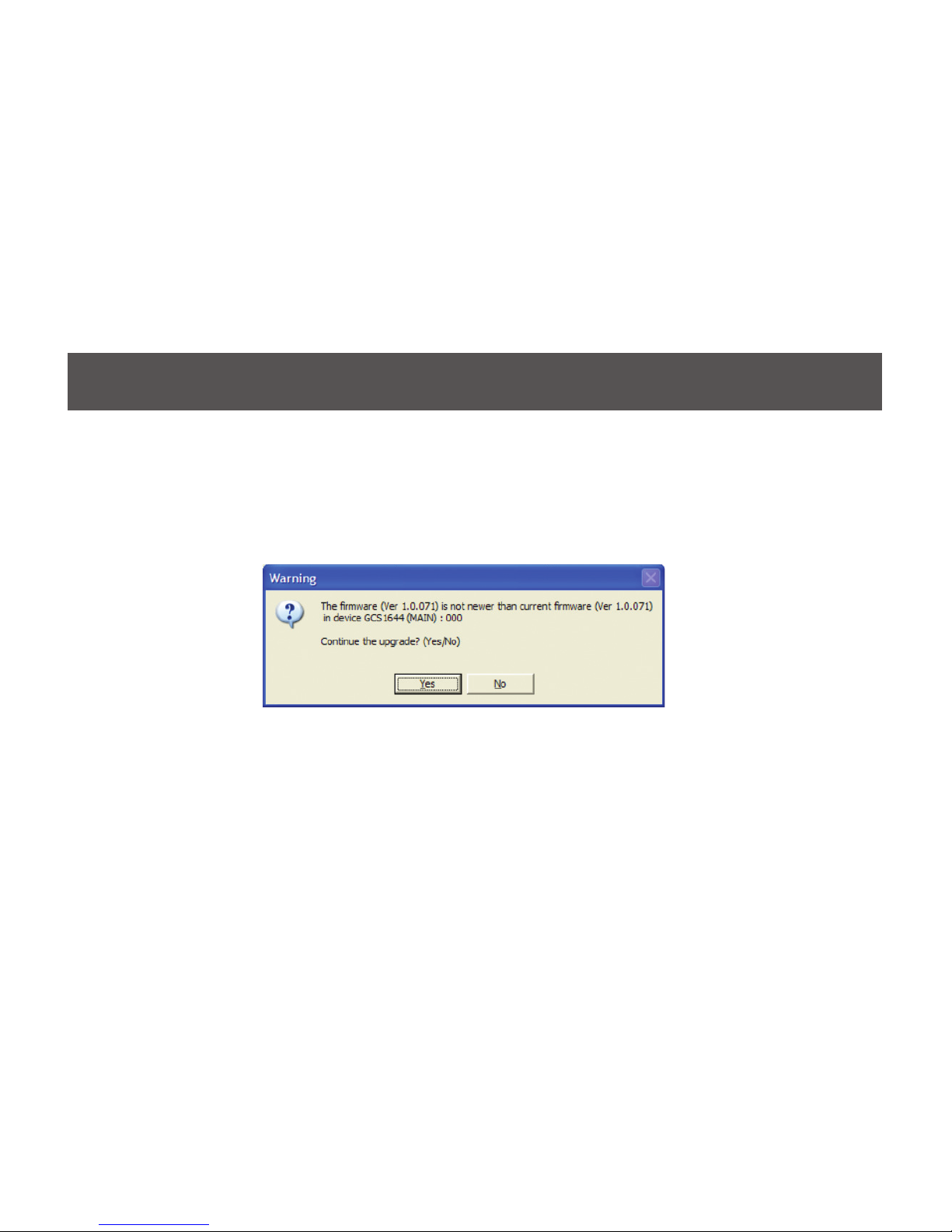
Step 8
If you have checked the “Check Firmware Version” checkbox, then the utility will check the current rmware
that is on your KVM. If the current rmware is newer than the rmware that you wish to upgrade to, a window
will popup and prompt you to ask if you wish to proceed. Simply click “Yes” to start the upgrade and “No”
to cancel the upgrade.
Note: If you did not check the “Check Firmware Version” checkbox, utility will perform the upgrade
automatically no matter what version of rmware you have in the KVM.
30
Page 31

Step 9
When the rmware upgrade is done, you will
see “Firmware upgrade OK” in the “Status
Messages” window. Then simply click “Finish”
to complete the whole firmware upgrade
process.
Final Step
Now the KVM will reset by itself and it will be
ready for usage after the rest.
31
Page 32

32
Upgrade Fail
If the Upgrade Succeeded screen doesn’t appear, it means that the upgrade failed to complete successfully.
In this case you should do the following:
Step 1
Power off the CS1642A / CS1644A by removing the power jack.
Step 2
Invoke Firmware Upgrade Mode by holding down the Mode Selection push button on the front panel
(see Mode Selection Push button, page 9) and power on the CS1642A / CS1644A. The orange LEDs
ash together.
Step 3
Go through the rmware upgrade procedure again.
Page 33

33
Federal Communications Commission (FCC) Statement
This equipment has been tested and found to comply with the limits for a Class B digital device, pursuant
to Part 15 of the FCC Rules. These limits are designed to provide reasonable protection against harmful
interference in a residential setting. This product generates, uses, and can radiate radio frequency energy
and, if not installed and used as directed, it may cause harmful interference to radio communications.
Although this product complies with the limits for a Class B digital device, there is no guarantee that
interference will not occur in a particular installation.
Page 34

34
This device has been tested and found to comply with the following European Union directives: Electromagnetic Capability (2004/108/EC), Low Voltage (2006/95/EC) and R&TTED (1999/5/EC).
CE Statement
Page 35

35
WE’RE HERE TO HELP YOU!
NEED ASSISTANCE SETTING UP THIS PRODUCT?
Make sure you:
1. Visit www.iogear.com for more product information
2. Visit www.iogear.com/support for live help and product support
Warranty Information
This product carries a 3 Year Limited Warranty. For the terms and conditions of this warranty, please go
to http://www.iogear.com/support/warranty
Register online at http://www.iogear.com/register
Important Product Information
Product Model
Serial Number
Limited Warranty
Page 36

36
IOGEAR
Toll Free 866-9-IOGEAR (USA)
Phone: 949-453-8782
19641 Da Vinci, Foothill Ranch, CA92610
www.iogear.com
support@iogear.com
Contact
©2013 IOGEAR. All Rights Reserved. PKG-M1087-b / M1088-b
IOGEAR, the IOGEAR logo, are trademarks or registered trademarks of IOGEAR. Microsoft and Windows are registered trademarks of Microsoft
Corporation. All other brand and product names are trademarks or registered trademarks of their respective holders. IOGEAR makes no warranty of
any kind with regards to the information presented in this document. All information furnished here is for informational purposes only and is subject to
change without notice. IOGEAR assumes no responsibility for any inaccuracies or errors that may appear in this document.
Page 37

37
Page 38

38
© 2013 IOGEAR
®
 Loading...