

Page 1

Wireless-G Notebook Network Card
User Manual (GWP512)
Page 2

Page 3

Welcome
Thank you for choosing IOGEAR® to serve your wireless needs. Soon, you will be sharing files or surfing
the Internet wirelessly. We hope you will have as much fun using your IOGEAR® Wireless-G Notebook
Network Card, as we had designing it.
Rest assured, your IOGEAR® Wireless-G Notebook Network Card is built rock-solid to ensure maximum uptime for you to stay up-and-running. If for any reason you have a problem, we stand behind our products
with an industry-leading 3 year factory warranty, so you can have peace-of-mind with your current and
future IOGEAR® purchases.
We want you to be happy with your purchase, so we have made every effort to ensure product quality,
reliability, and ease-of-use.
©2004 IOGEAR. All Rights Reserved. PKG-M0109
IOGEAR, the IOGEAR logo, is the trademark or registered trademarks of IOGEAR, Inc. Microsoft and Windows are registered trade-
marks of Microsoft Corporation. IBM is a registered trademark of International Business Machines, Inc. Macintosh, G3/G4 and iMac are
registered trademarks of Apple Computer, Inc. IOGEAR makes no warranty of any kind with regards to the information presented in this
document. All information furnished here is for informational purposes only and is subject to change without notice. IOGEAR, Inc. assumes
no responsibility for any inaccuracies or errors that may appear in this document.
Page 4

T able of Contents
Package Content
Overview
Features
Requirements
Introduction
Installation
Uninstallation
Configuration Utility
WinXP Zero Configuration Utility
WP A Configuration Utility
Specification
T echnical Support
○○○○○○○○○○○○○○○○○○○○○○○○○○○○○○○
○○○○○○○○○○○○○○○○○○○○○○○○○○○○○○○○○○○
○○○○○○○○○○○○○○○○○○○○○○○○○○○○○○○○○○○
○○○○○○○○○○○○○○○○○○○○○○○○○○○○○○○○○
○○○○○○○○○○○○○○○○○○○○○○○○○○○○○○○○○○
○○○○○○○○○○○○○○○○○○○○○○○○○○○○○○○○○○
○○○○○○○○○○○○○○○○○○○○○○○○○○○○○○○○○
○○○○○○○○○○○○○○○○○○○○○○○○○○○○○○○
○○○○○○○○○○○○○○○○○○○○○○○○○○
○○○○○○○○○○○○○○○○○○○○○○○○○○○○○
○○○○○○○○○○○○○○○○○○○○○○○○○○○○○○○○○
○○○○○○○○○○○○○○○○○○○○○○○○○○○○○○○○
Radio and TV Interference Statement
Limited Warranty
○○○○○○○○○○○○○○○○○○○○○○○○○○○○○○○○
Regulatory Compliance FCC Warning
○○○○○○○○○○○○○○○○○○○○○○○○
○○○○○○○○○○○○○○○○○○○○○○○○
2
3
4
5
6
10
31
34
56
67
74
75
76
77
78
Page 5

This package contains:
• IOGEAR
®
Wireless 802.11g PC Card
• CD ROM containing Driver, Configuration Utility, Odyssey Client f or Marvel
(client for WPA application) and User’s Manual
• Quick Start Guide
• Acrobat Reader 6.0
2
Package Contents
Page 6

Overview
IOGEAR®’s Wireless-G Notebook Network Card is a sleek and versatile device for both small and home
office users. With IOGEAR®, you can surf the Internet, share files, chat with your friends, and....Wirelessly!
Our simple, easy-to-use, setup wizard will have you up-and-running in minutes. Moreover, our turn-key
Firewall and Wireless Security packages keep you safe on the ‘net.
Remember, IOGEAR®’s Wireless-G Notebook Network Card gives you the wireless connectivity all in a small,
cost-effective, and reliable setup. Go with IOGEAR®, and go Wireless!
3
Page 7

Features
• 54 Mbps wireless connection speed - up to five times faster than previous 802.11b technology
• Sleek, compact antenna is designed for maximum agility
• Simple user setup & diagnostics utilities
• Odyssey security client (from Funk Software) included, for strong WLAN securities (supporting EAP-TTLS,
EAP-PEAP , EAP-TLS , and LEAP).
• Compliant with FCC Part 15.247 for US, EN 300-328 for Europe, and RCR STD-33A and ARIB
STD-T66 for Japan
• Backward compatible with 802.11b wireless networks, access points, hot spots and other devices
• Solid 3-year manufacturer warranty - built to last!
4
Page 8

System Requirements
• Pentium® class notebook computers with one available CardBus slot
• Microsoft® Windows® 98SE, ME, 2000, XP
• CD-ROM drive
• Using Odyssey Client for Marvell, your computer must be running Microsoft Internet Explorer 5.5 or later.
• Using WPA function, make sure there is a WPA-enabled Access Points in the network environment.
5
Page 9
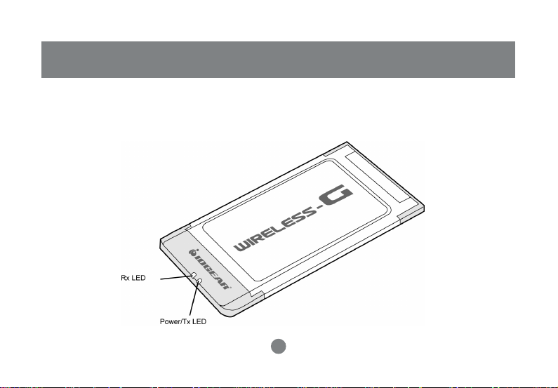
Introduction
When the adapter card is not associated with any wireless network devices, the Power/Tx LED will stay solid
green; Rx LED will be off. When both LEDs are blinking green, the adapter card is scanning/connecting to
an wireless network. When the adapter card is associated, Power/Tx LED indicates transmitting activity; Rx
LED indicates receiving activity.
6
Page 10
Introduction
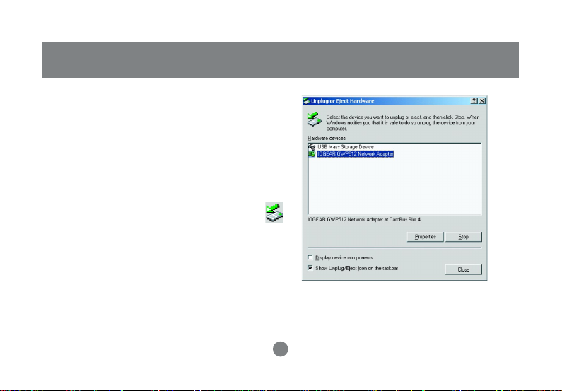
Ejecting the Network Adapter
Please always disable the network adapter prior
removing the adapter from the PCMCIA slot. The
network adapter supports hot-swappable feature so
you don’t have to power off the notebook to remove
the adapter.
1. Double click the Unplug or Eject Hardware Icon
resides on the Windows system tray and click Stop
from the Unplug or Eject Hardware dialog box.
7
Page 11
Introduction
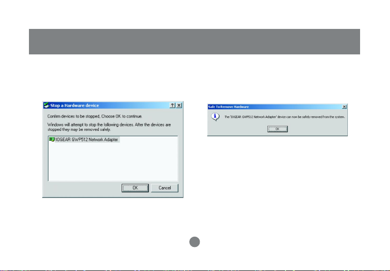
2. Click OK to confirm that you are going to stop the
adapter.
3. The following screen prompts that you can
remove the adapter. Click OK button to close
the dialog box.
8
Page 12

Introduction
4. Push the lever of your notebook PCMCIA slot to
eject the adapter now.
Note: Don’t eject the network adapter when data
transmission is taking place.
9
Page 13
Driver Installations
If you have connected the notebook adapter to your
computer, please remove it first.
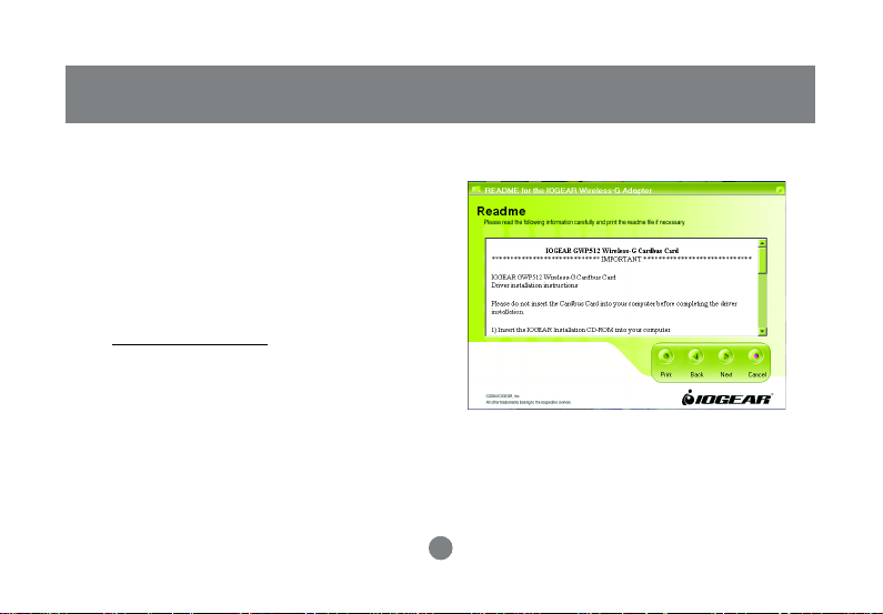
1. Insert the Driver and Utility CD into CD Drive.
2. A series of introduction screens will show up.
It runs on Macromedia Flash. If your computer
doesn’t have the Flash player installed, please
www.macromedia.com to download the plug-in
visit
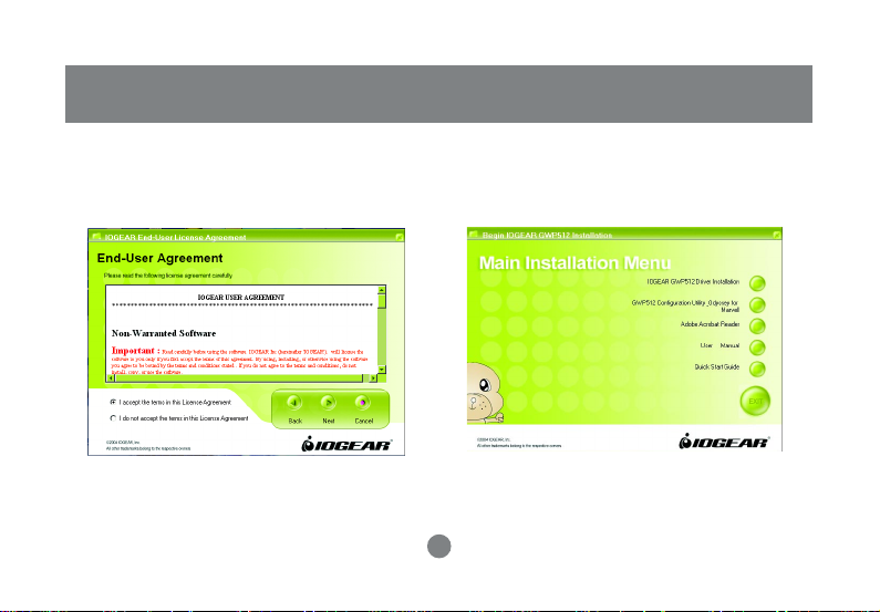
3. Next, a Read Me screen will be brought up.
Please read it through carefully, then click Next.
Installation
10
Page 14
Installation
4. Click the button of “I accept the terms in the
license agreement”. Click Next
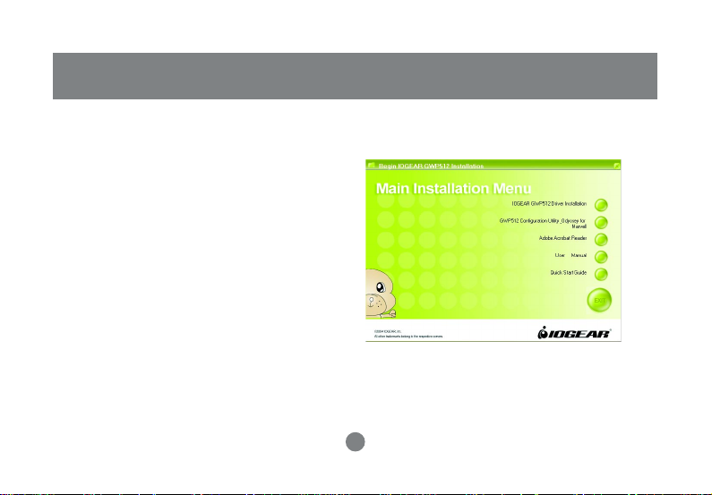
5. A Main Installation Menu will show.
Click the button of IOGEAR GWP512 Driver
Installation.
11
Page 15

6. When it completed, an information window
will pop up. Please click OK, then it will
return to main menu.
Note: The following procedures are operated in
Windows 2000.The steps and screen shots are
similar for the other supported OS (such as Win
98SE, ME and XP).
Installation
12
Page 16
Installation
Installing the Network Adapter Driver
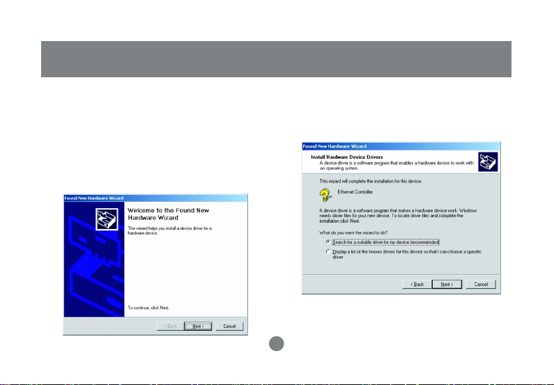
1. Insert the Network Adapter into the PC card slot.
Align the card properly.
2. When Windows 2000 recognizes the adapter, the
Found New Hardware Wizard dialog box appears.
Click Next.
3. Select the “Search for a suitable driver for my
device.” and click” Next”.
13
Page 17
Installation
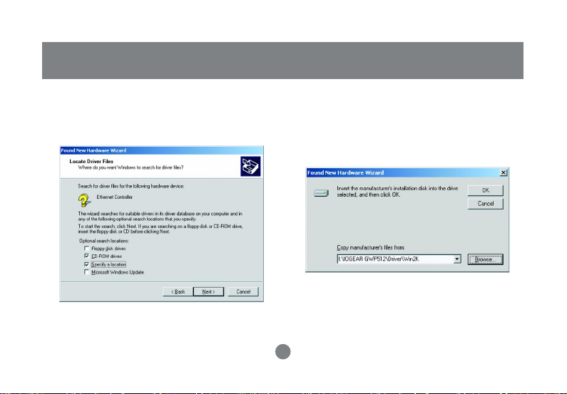
4. Select the “Specify a location” checkbox. Click
Next.
5. Click “Browse”, browse to the X:\IOGEAR
GWP512\Driver\Win2k directory and click OK.
Note: X is the drive letter for user’s CD-ROM
drive.
14
Page 18
Installation
Note:
Windows 98SE users, please specify to IOGEAR
GWP512\Driver\Win98 directory.
Windows ME users, please specify to IOGEAR
GWP512\Driver\WinME directory.
Windows XP users, please specify to IOGEAR
GWP512\Driver\WinXP directory.
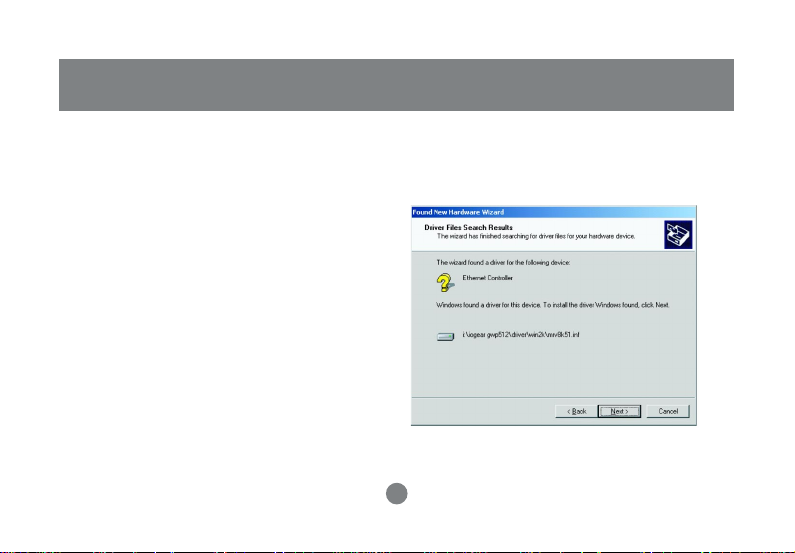
6. The wizard will display the location of the driver.
Click on the Next button.
15
Page 19
Installation
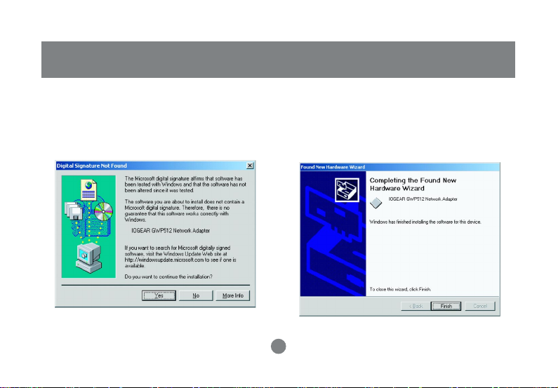
7. The Microsoft Digital Signature Not Found dialog
box could appear at this point. A Microsoft digital
signature is not required for the driver installation.
Click “Yes” to continue.
8. After a while, the wizard will report that the
hardware installation is complete. Click Finish.
16
Page 20
Installation
Configuration Utility and Odyssey for Marvell Utility Installations
The Odyssey For Marvell Utility will be installed after
the completion of Configuration Utility .
The Odyssey Client helps the user to configure the
WP A function. WPA is an implementation based on a
subset of the 802.11i standard and provides
enhanced security for wireless networks when used
with the Temporal K ey Integrity Protocol (TKIP) and
the Michael message integrity check (MIC)
algorithms. Be sure there is an access point
supports WPA in the network environment for using
the Odyssey for Marvell utility.
1. Click on the button of GWP512 Configuration
Utility and Odyssey Client for Mavell from Main
Installation Menu.
17
Page 21
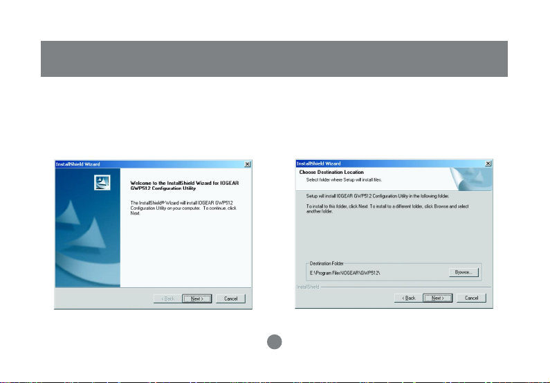
2. The InstallShield Wizard is preparing to install the
configuration utility. Click Next.
Installation
3. In the
Destination Folder
to confirm the
application software. If you would like, you may
change the destination folder to another location.
Click Next.
18
Destination Folder
screen, you are asked
for the
Page 22
Installation
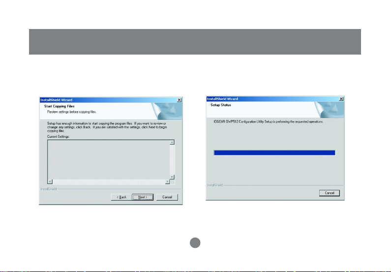
4. Select a program folder and click Next.
5. The InstallShield Wizard is installing utility.
19
Page 23
Installation
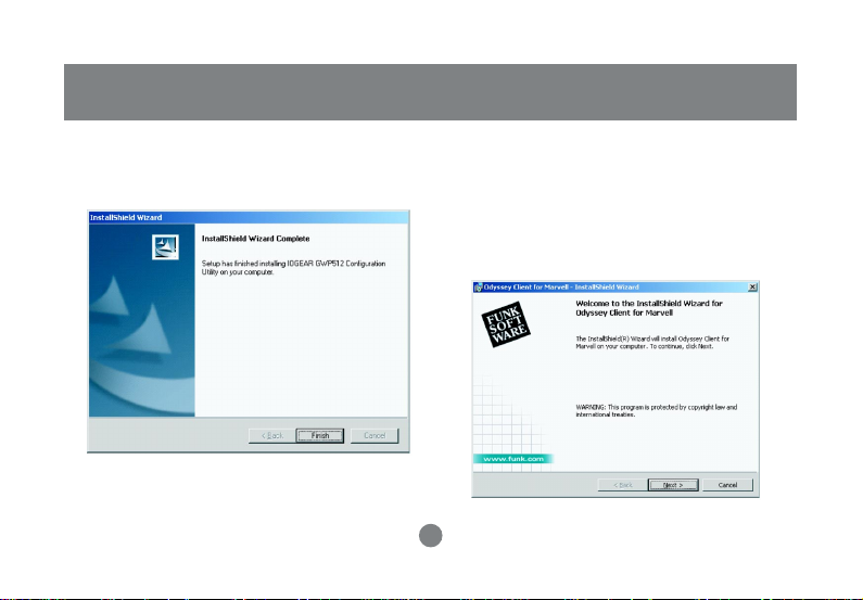
6. Click Finish to complete the Utility installation.
7. The InstallShield Wizard continues to install the
Odyssey Client Manager for Marvell. The
Odyssey Client Installation Wizard window
appears. Click Next. If you don’t want to install
the Odyssey for Marvell Utility, you can click
Cancel to close the installation.
20
Page 24
Installation
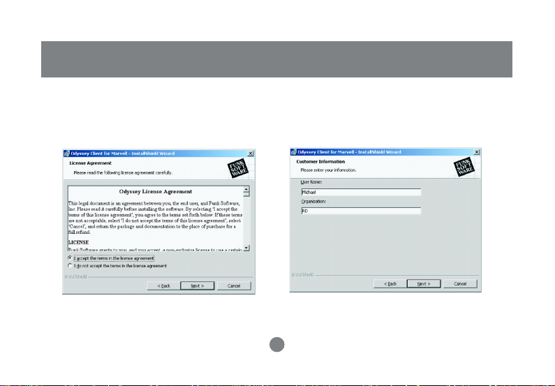
8. Select “I accept the terms in the
license agreement”. Click Next.
9. Enter a User Name and Organization in the
Customer Information window. Click Next.
21
Page 25
Installation
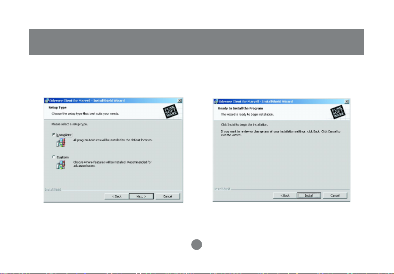
10. Select the button of Complete. Click Next 11. Click Install to install the program.
22
Page 26
Installation
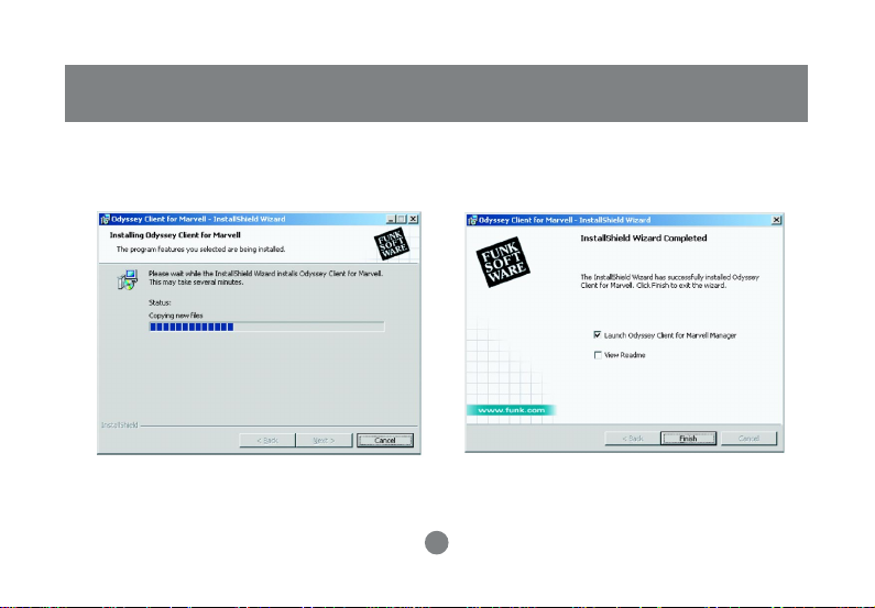
12. The InstallShield Wizard starts copying files to
your PC.
13. When the installation is completed, the Wizard
Completed window appears. Click Finish.
23
Page 27

Installation
14. The Configuration Wizard window appears. Click
Next.
15. Click Finish to complete the configuration Wizard.
24
Page 28

Installation
16. The Odyssey for Marvell Utility icon will appear in
the system tray automatically. If the network
adapter plugged and connected with a wireless
network, the Configuration Utility will launch
automatically , and showing green icon in the
system try. If it does not launch and you cannot
get wireless connection, please open the
Configuration Utility from Windows Start >
Programs > IOGEAR GWP512 > IOGEAR
GWP512 Configuration Utility.
Configuration Utility Icon
Odyssey for Marvell Utility Icon
Verifying Driver Installation
1. Right-click mouse button on the My Computer icon
on your Windows desktop, and select Properties
from the pop-up menu.
25
Page 29

Installation
2. The System Properties screen will pop-up.
Under Hardware tab , clic k Device Mana ger .
3. After clicking Device Manager, the following
screen will be shown.
Click on the + symbol in front of “Network
adapters” and see if an item labeled IOGEAR
GWP512 Network Adapter is visible. If you don’t
see the item below the network adapter icon but
a”?” or “!” symbol is displayed, it means that the
driver installation was unsuccessful. Highlight
“IOGEAR GWP512 Network Adapter”, right-click
mouse button and select “Properties”.
26
Page 30

Installation
4. Click the General tab, if the Device Status field
reports that “This device is working properly”, it
means that the driver has been installed
successfully.
TCP/IP Setup Procedure
After the network adapter driver and configuration
utility are installed, the TCP/IP address for the
network adapter must be set up in order to communicate with other wireless LAN access points and
clients, and to have Internet access.
1. Right-click on My Network Places and select
Properties from the pop-up menu.
27
Page 31

Installation
2. Find the “Local Area Connection” that is
associated with the Network Adapter. Right-click
on the connection and select Properties.
3. Select “Internet Protocol (TCP/IP)” and click
Properties.
28
Page 32

Installation
4. Select “Obtain an IP address automaticall y”,
if the network adapter will be linked to a Wireless
AP providing DHCP service. Or, please click “Use
the following IP address” and input an IP address
and subnet mask. IP configuration information
(DHCP or assigned IP address, Gateway and DNS
server IP addresses) is usually obtained from the
corporate IT staff.
Note: The IP Address you assign to all computers
must be in the same IP Address range, and the
Subnet Mask must be the same for all computers on
your network.
For example:
If the first computer is assigned an IP Address of
10.35.1.3 with a Subnet Mask of 255.255.255.0,
then the second computer can be assigned an IP
Address of 10.35.1.4 with a Subnet Mask of
255.255.255.0,.. etc.
29
Page 33

Installation
5. After completing IP configuration information, click
OK to both “Internet Protocol (TCP/IP) Properties”
and “Local Area Connection Properties” to
complete the IP configuration.
6. Choose Start > Programs > Accessories >
Command Prompt to open the DOS command
prompt window.
7. T ype “ipconfig” at the D:\> prompt to determine
if the TCP/IP configuration has taken effect.
30
Page 34

Uninstallation
Uninstalling the Network Adapter Driver
1. To remove the driver from the OS, go to
Start>Settings>Control Panel.
2. Double-click System.
31
Page 35

Uninstallation
3. Under Hardware tab, click Device Manager.
Double-click Network adapters. Right-click mouse
button on “IOGEAR GWP512 Network Adapter”,
and choose Uninstall. Click OK to uninstall the
device.
4. Click OK to confirm that you are going to uninstall
the driver.
32
Page 36

Uninstallation
Uninstalling the Network Adapter Configuration Utility
1. The user can uninstall the Configuration Utility from
Windows Start menu -> Programs -> IOGEAR
GWP512-> Uninstall to remove the configuration
utility.
33
Page 37

Configuration Utility
Network Adapter Configuration Utility
The Configuration Utility can be launched from
Windows Start -> Programs -> IOGEAR GWP512 ->
IOGEAR GWP512 Configuration Utility.
After launched, the utility icon will reside on the
Windows system tray and provides at-a-glance
feedback about the device’s status by changing
appearance.
Status 1:
The wireless network adapter is not plugged in.
Status 2:
The wireless network adapter is trying to associate
with other network devices in service range.
34
Page 38

Configuration Utility
Status 3:
The wireless network adapter is associated with a
network device.
Right-click mouse button on the icon, there will be a
shortcut menu.
• Restore: Select this option and the Utility Main
screen will appear on the top of all Windows
applications you have opened.
• Turn Radio off: Click the T urn Radio Off will power
off the network adapter.
• Exit: Close the utility and the icon will exit from the
system tray, too.
35
Page 39

Utility Main Windo w
Configuration Utility
The Configuration utility is separated into seven
categories:
• Network Status: Display the status of the
network you are connecting to.
• Profile Manager: Display the current profile and
allows you to create, modify and delete profiles.
• Site Survey: List all available network devices in
range.
• Statistics: You can view the information of
wireless receiving and transmitting data.
• Advanced: Allows you to perform advanced
configuration.
• Admin: Allows you to import or export profiles.
• About: Shows the firmware and utility versions
and MAC address of the network adapter.
36
Page 40

Configuration Utility
Configuration Utility – Network Status T ab
Select Profile
Displaying the name of the profile in use. Click
the down-arrow button to select profiles you
have created previously. You may modify,
create and delete profiles through the Profile
Manager tab.
37
Page 41

Configuration Utility
Link Information
Contains information of current connection.
• Status:
- Connected: Indicates the adapter is
connected with a wireless network.
- Card Unplugged: Card not plugged in, or
plugged in but not recognized.
- No Connection: Card plugged in but can’t find
a wireless network.
- No Radio: Card plugged in but the radio is
turned off.
• Network SSID: Indicates the SSID of the
connected wireless device.
• Network T ype: Indicating the current network
type the adapter uses. It could be Ad hoc or
Infrastructure.
• Network BSSID: Shows the associated device’s
MAC address in the form of hex digits.
• Security: Indicates whether the connected device
has the WEP function enabled or not.
- Security OFF: It means that the connected
device isn’t using enable WEP function.
- WEP: It means that the connected device uses the
WEP function.
• Link Speed: Current link speed.
38
Page 42

Configuration Utility
Internet Protocol
Display information of Internet protocol.
Signal Strenth
The green color bar indicates the signal is weak or
strong. The longer the color bar,the better connection.
39
Page 43

Configuration Utility
Channel
Display the channel in use and the dynamic diagram
shows the Transmit (TX) and Receiving (RX) rate
being monitored.
Radio Off
Click the checkbox and the adapter will be turned off.
40
Page 44

Configuration Utility
Configuration Utility – Profile Manager T ab
The profile manager tab allows you to modify, create
or delete profiles.
Profile List Window
List all available profiles.
If the Default box is checked, it means the profile
is used in auto-configuration mode when the
connection is lost. If unchecked, the profile will be
excluded in auto-configuration.
• Apply Profile: Apply the selected profile.
The buttons below are used to control the window .
- Move Up/Down: Move the selected profile up or
down.
- Delete: Delete a profile.
- Create: Create a new profile. Click the Create
button and follow on-screen description to create
a new profile.
- Save: Save changes you have made to a
selected profile.
41
Page 45

Profile Setting
The profile setting displays information of the
selected profile.
It is divided into three sub-tabs.
Network Info:
• Profile Name: name of the selected profile.
• Network SSID: the connected netw ork SSID.
You can type a specific Network SSID in this field
to limit the link to an access point or other
computer equipped with a wireless LAN adapter.
If you leave this field blank, the wireless LAN
adapter will try to build the link with any wireless
device that has better signal and link quality.
Configuration Utility
42
Page 46

Configuration Utility
• Network T ype: the type of network environment to
which you are connected. It could be infrastructure
or ad-hoc. Infrastructure – This type of network
connection needs an access point in range. All
communication is done through this access point.
Ad hoc – A peer-to-peer mode of operation. This
type of link is established from client to client
without any access point.
Security Tab:
The Security tab provides WEP (Wired Equivalent
Privacy) function to ensure a securer networking
communication and prevent unauthorized access to
your wireless network. The WEP keys configured for
your wireless device must be same as those
configured for the access point or wireless LAN
adapter it associates with.
• Encryption Method: Click the down-arrow button to
select Security Off or WEP.
• Authentication Mode: Click the down-arrow button to
select one. The authentication type should be same
among those connected devices.
- Open system: With this setting, any station in the
Wireless LAN can link with the Access Point.
43
Page 47

- Shared Key: only stations using a shared key
encryption identified by the Access Point are
allowed to associate.
• WP A – Wi-Fi Protected Access. Please Refer to
Page.67 for WPA function configuration.
• WEP Key Setting: The WEP key setting is
available only when the WEP is activated. Click
Configure WEP Keys button to configure the WEP
settings.
- Key Format: This utility supports both Hexadeci-
mal and ASCII key formats. Click the down-arrow
button to choose one format. Only digits 0-9 and
letters A-F are valid entries if you select
hexadecimal format.
- Key Size: Click the down-arrow button to select
40-bit or 104-bit key size.
Configuration Utility
44
Page 48

Configuration Utility
• Transmit Key 1-4: These four fields allow you to
set four different 40-bit or 104-bit keys for
encryption. This item is a very convenient and
useful function when you want to match the WEP
keys with different APs. After setting the WEP
keys for specific AP or wireless LAN card, instead
of entering the WEP key every time, you can just
click the button in front of WEP key to enable the
association.
Protocol:
• Do not change settings:
If the box is checked, then, all settings on this tab
can’t be change.
• Use below settings:
- Power Save Mode: This field provides two
options of power management: Continuous
Access and Max Power Save. Click the pull-down
menu to select the mode you desire.
- Preamble (802.11b): Select Auto or Long. The
default setting is Auto.
- Transmit Rate: This field provides options for
selecting data-transmitting rate of the wireless
LAN adapter. You can click the down-arrow button
to select one option. By default, the data rate is
set to Auto allowing Tx rate to the highest
possible rate. It’s recommended that you select
the Auto option.
45
Page 49

> Fragment Threshold: This field is to define the
maximum data frame size this wireless LAN
adapter will transmit and to improve the efficiency
of data transmitting.
> RTS/CTS Threshold: This field is to set the packet
size at which the AP issues a Request-To-Send (or
Clear-T o-Send) frame before sending the pack et.
Type the value in this field and the effective range
is from 0 to 2347.
> Rest Button: Click Reset button returns the
protocol settings to their default values.
Configuration Utility
46
Page 50

Configuration Utility
Site Survey T ab:
Click the Site Survey tab and the following screen will
be displayed.
Connected 802.11g
access point Icon
802.11b
Access point Icon
47
Page 51

Configuration Utility
From the Site Survey page, you can search all
access points and network adapters that are within
the service range of the network adapter. Click
Refresh button, and the network adapter will start to
search access points and WLAN adapters and show
the result on the list.
The list includes information about the Network SSID
and MAC address of the access point and WALN
adapter, the signal strength, the channel where the
access point and WLAN adapter operates, and
whether or not WEP encryption is used. You can
highlight the access point or WLAN adapter you want
to associate and click Associate or double click on
your choice to connect that device.
In the figure, you can see there are one 802.11b
access point and one 802.11g access point within the
service range of the network adapter. You may click
the Refresh button to update this list and use the
scroll bar to see more information.
Access Point Filter
This option lets you customize which sites will be
displayed in the site survey list.
Check the checkbox to enable individual wireless
mode.
48
Page 52

Configuration Utility
Advanced Filter
Click the Filter button and the Advanced Filter dialog
box will be brought up. It helps you take more control
of searching AP or network adapter in range.
Network SSID:
• Any SSID: If selected, any SSID will be used.
• Find network with this SSID: The utility will search
the specific SSID.
• Network BSSID:
• Any BSSID: If selected, any BSSID is used.
• Find network with this BSSID:
The utility will search the specific BSSID.
• Select Channel: You can check individual channel,
all channels or clear all channels.
49
Page 53

Statistics Tab:
Click the Statistics tab and the following screen will
be displayed.
Configuration Utility
The statistics window is divided into two parts –
transmit and receive. From the window, you can view
the instantaneous wireless receive and transmit data
information.
50
Page 54

Configuration Utility
Advanced T ab:
Click the Advanced tab and the following screen will
be displayed.
The tab provides more advanced protocol control of
the wireless network adapter
Wireless Card
Display the current network adapter.
51
Page 55

Configuration Utility
Protocol
• Power Save Mode: Click the down-arrow button to
select one option.
• Radio Preamble: Click the down-arrow button to
select Auto or long.
• T ransmit Antenna: Click the down-arrow b utton to
set the transmit antenna mode, either Antenna 1,
antenna2 or diversity.
• Receive Antenna: Click the down-arrow button to
set the receive antenna mode, either diversity On
or diversity Off.
• T ransmit Rate: the range of the data rate depends
on the type of AP the card is connected to.The
default value is Auto.
• Fragment Threshold: Set the fragmentation
threshold and the default value is 2346.
• RTS/CTS Threshold: Set the pac k et siz e at which
the AP issues a Request To Send (or Clear-To-Send)
frame before sending the packet.
Don’t forget to click Apply Changes to make your
configuration take effect.
52
Page 56

Configuration Utility
Link loss or no connection
Check the item, whenever a link loss or no
connection, the auto-configuration feature will try to
build a connection according to the checked profiles
in the Profile Manager.
Admin Tab:
Click the Admin tab and the following screen will be
displayed.
53
Page 57

You can import or export profiles through this tab.
T o import a profile:
• Click the Import Profiles button.
• Select the path and file name of the profile.
• Click Open.
Configuration Utility
To export a profile:
• Click the Export Profiles button.
• Select the path and file name of the profile.
• Click Save.
54
Page 58

Configuration Utility
About T ab:
Click the About tab and the following screen will be
displayed.
From the About tab, you can view the product
version including the driver version, utility version
and firmware version. The MAC address of the
wireless LAN adapter and the regulatory domain
are also shown on this page.
55
Page 59

WinXP Zero Configuration Utility
After you have properly installed the wireless network
adapter driver, you may...
1. Right-click mouse button on the network connection
icon residing on the system tray, and click “View
Available Wireless Networks”.
2. The following Connect to Wireless Netw ork dialog
box will be displayed. You can click Connect to
start the wireless connection or click Advanced
button to do further configuration.
56
Page 60

WinXP Zero Configuration Utility
3. Click the Advanced button and the Local Area
Connection Properties dialog box will be displayed.
Click the Wireless Networks tab from the Wireless
Network Connection Properties dialog box. Select
the box of “Use Windows to configure m y wireless
network settings” to enable automatic wireless
network configuration.
Note: If you want to use the configuration utility we
provide, you have to clear the check of “Use Windows
to configure my wireless network settings” item.
57
Page 61

Infrastructure Mode Setup Procedure
1. F rom the Wireless Network tab, clic k Refresh
button to update all the available network devices in
range.
2. Click the network name under the “Available
networks” and click Configure. The Wireless
Network Properties dialog box will be displayed.
WinXP Zero Configuration Utility
58
Page 62

WinXP Zero Configuration Utility
3. If the network you select requires WEP key,
then the “Data encryption (WEP enabled)”
check box is selected by default. Select the
“The key is provided for me automatically”
check box if the WEP key is automatically
provided for you. The driver will then use the
Default Encryption key. If not, you have to clear
the check and manually enter the network key.
In this example, you have to type the WEP
keys. After you enter the WEP keys, you can
click OK to close the Wireless Network
Properties dialog box and the system will take
you back to Wireless Network Connection
Properties dialog box.
4. Click OK to save your configuration and the
Wireless Network Connection Properties will be
closed.
5. When the network connection you have configured
is available, the following bubble message will be
shown on the system tray.
59
Page 63

6. Right-click on the network icon and
select “View Available Wireless Network”. Click
Advanced button from the Connect to Wireless
Network dialog box and you can find that there is a
blue circle on the ESSID: Winson you have
configured in Wireless Network Connection
Properties dialog box. It means that you have
successfully built the connection. You may refer to
the section of how to do TCP/IP setup to configure
your wireless LAN adapter. After the TCP/CP
configuration is done, you can access the Internet
through the wireless connection you have built.
WinXP Zero Configuration Utility
60
Page 64

WinXP Zero Configuration Utility
7. Furthermore, you can highlight a network
connection and click Move up or Move down to
change the order of the wireless networks in the
Preferred networks. For Windows XP, it will alw ays
choose the first one in the Preferred networks to
connect. To remove a wireless network from the list
of preferred networks, select the wireless network
that you want to remove, and then click Remove.
61
Page 65

Ad-hoc Mode Setup Procedure
1. Click Refresh button to update all available
devices in range from Wireless Network
Connection.
2. Select the ad hoc network name under “Available
networks” in the Wireless Networks tab, and
click Configure.
WinXP Zero Configuration Utility
62
Page 66

WinXP Zero Configuration Utility
3. In the Wireless Network Properties dialog box, the
“This is a computer-to-computer (ad hoc) network;
wireless access points are not used” check box is
selected by default.
4. If the network adapter you want to connect has
enabled the WEP function and then the “Data
encryption (WEP enabled)” check box is checked.
You can select the “The key is provided for me
automatically” check box if the WEP key is
automatically provided for you. The driver will then
use the Default Encryption key. If not, you have to
clear the check and manually enter the network
key. In this example, you have to type the WEP
keys. After you enter the WEP keys, you can
click OK to close the Wireless Network Properties
dialog box and will go back to Wireless Network
Connection Properties dialog box.
63
Page 67

5. Click OK to save your configuration and close the
Local Area Connection Properties dialog box. Rightclick mouse button on the network icon on the
system tray and open the Connect to Wireless
Network dialog box again. Click Advanced button,
and you can see that there is a blue circle on the
wireless network adapter icon.
WinXP Zero Configuration Utility
64
Page 68

WinXP Zero Configuration Utility
6. You may refer to the section of how to do TCP/IP
setup to configure your wireless LAN adapter in
Windows XP. After the TCP/CP configuration is
done, you can share data between these wireless
devices.
7. Open Windows Explorer and type the connected
wireless network adapter IP address in the
Address field. The folder that the associated
computer shares will be displayed. Now , you can
share data with it,
65
Page 69

Network Operating Mode Selection
1. Click “Advanced” button from the Local Area
Connection dialog box, and you can select
network operating mode you want to use.
WinXP Zero Configuration Utility
2. If you want to connect to an ad hoc network only,
you can click the button of “Computer-to-computer
(ad hoc) networks only”. Click the button of
“Access point (infrastructure) networks only”,
and only the available access points in range will
be displayed in the available networks box. You can
click the button of “Any available network (access
point preferred)”, and then both access points
and wireless network adapters will be displayed in
the available networks box.
66
Page 70

WP A Configuration
WP A Configuration
There are two configuration utilities to setup wireless
connectivity with an AP that supports WPA – Windows
XP: Zero Configuration Utility and Odyssey For
Marvell Utility .
For Windows XP operating system, use the Windows
built-in Zero Configuration Utility when associating with
a WPA-enabled AP. The user must ensure Service
Pack #2 and WPA Hotfix Q815485 is installed. (Please
see note.)
For Windows 2000, 98SE and ME operating system,
please use the Odyssey For Marvell utility when
associating with a WPA-enabled AP. The Odyssey For
Marvell Utility provides two ways of WPA operations:
- connect with a RASIUS server.
- connect with a WPA-pre-shared key (WPA_PSK)
configuration.
Note:
The WPA client for Windows XP can be found in the
Microsoft Knowledge Base Article 815485 (http://
support.microsoft.com/default.aspx?scid=kb;enus;815485) or downloaded directly from Microsoft
http://www.microsoft.com/downloads/
details.aspx?FamilyID=009d8425-ce2b-47a4-abec274845dc9e91&displaylang=en
After installed, the Windows W PA Client will update
the wireless network configuration dialog boxes to
support new WP A options.
67
Page 71

WP A Configuration
1. Click Connect To>Wireless Network
Connection to bring up the dialogue window
of Wireless Network Connection Status.
Click the Properties box to bring up next
dialogue window.
2. In the Wireless Network Connection
Properties window, under Wireless
Networks tab, please check the box of
“Use Windows to configure my
wireless network settings” to turn on
the Wireless Zero Configuration service.
Select the wireless access point you
want to associate to, then click Config-
ure box at the right side to bring up next
dialogue window.
68
Page 72

WP A Configuration
3. Set up your WPA configuration by selecting
the Network Authentication mode and
Data encryption, and input same Network
key as you input at the Wireless-G
Broadband Gateway. Then, you are served
by a more secured wireless network.
69
Page 73

Odyssey for Marvell Configuration Utility
The Odyssey for Marvell configuration utility can be
launched from the Windows Start menu > Programs
> Marvell > Odyssey Client for Marvell > Odyssey
Client Manager for Marvell. The main screen will
show up.
You can click the Help menu and select Help Topics
to browse more information regarding the operation
of the Odyssey for Marvell Utility. The following
section describes how to configure the WPA through
RADIUS server and WPA-PSK.
70
WP A Configuration
1. Uncheck the Connect to network box.
2. Click Scan.
3. Select an AP to be associated with in the Network
Connection Properties box.
4. Configure the WPA in the Network Properties box.
Page 74

WP A Configuration
WPA-PSK
To connect with an AP using the Pre-shared key
configuration (WPA-PSK), uncheck items in
Authentication box. In the Passphrase box, enter
the configuration key. The key should match the
one set in AP.
WPA
To connect with an AP through RADIUS server, click
the items in Authentication box.
71
Page 75

WP A Configuration
1. Click OK.
2. RADIUS Server Client Manager, click the Profile
box.
3. Click Properties. In the Edit Properties screen.
Click the User Info tab. Uncheck the Permit login
using password box. Check Permit login using my
certificate.
72
Page 76

WP A Configuration
4. Click the Authentication tab. Uncheck the box of
Validate server certificate. Choose authentication
protocol from inside the box.
5. Click Add and choose EAP/TLS from the list. Click
OK.
6. In the Client Manager main screen, choose
Connection.
7. Check the Connect to network box.
8. The network adapter now connects to the WPAenabled AP through the RDAIUS server.
73
Page 77

Specification
74
Page 78

Tec hnical Support
If you need technical support, please check out our IOGEAR Tech Info Library (T.I.L.) at
www.iogear.com/support for the latest tips, tricks, and troubleshooting. The IOGEAR T.I.L. was
designed to provide you with the latest technical information about our products. Most of the answers to
your questions can be found here, so please try it out before contacting technical support.
Technical support is available Monday through Friday from 7:30 am to 5:30 pm PST and can be reached
at (949) 453-8782 or by email support@iogear.com.
75
Page 79

Radio & TV Interference Statement
WARNING!!! This equipment generates, uses and can radiate radio frequency energy and, if not installed and
used in accordance with the instruction manual, may cause interference to radio communications. This
equipment has been tested and found to comply with the limits for a Class B computing device pursuant to
Subpart J of Part 15 of FCC Rules, which are designed to provide reasonable protection against such
interference when operated in a commercial environment. Operation of this equipment in a residential area is
likely to cause interference, in which case the user at his own expense will be required to take whatever
measures may be required to correct the interference.
76
Page 80

Limited Warranty
IN NO EVENT SHALL THE DIRECT VENDOR’S LIABILITY FOR DIRECT , INDIRECT, SPECIAL, INCIDENTAL
OR CONSEQUENTIAL DAMAGES RESUL TING FR OM THE USE OF THE PRODUCT, DISK OR ITS DOCUMENT A TION EXCEED THE PRICE P AID FOR THE PRODUCT .
The direct vendor makes no warranty or representation, expressed, implied, or statutory with respect to the
contents or use of this documentation, and especially disclaims its quality, performance, merchantability, or
fitness for any particular purpose.
The direct vendor also reserves the right to revise or update the device or documentation without obligation
to notify any individual or entity of such revisions, or updates. For further inquires please contact your
direct vendor.
77
Page 81

Regulatory Compliance FCC Warning
This device complies with Part 15 of the FCC Rules.
Operation is subject to the following two conditions: (1) this device may not cause harmful interference, and (2)
this device must accept any interference received, including interference that may cause undesired operation.
This equipment has been tested and found to comply with the limits for a Class B digital device, pursuant to
part 15 of the FCC Rules. These limits are designed to provide reasonable protection against harmful
interference in a residential installation.
This equipment generates, uses and can radiate radio frequency energy and, if not installed and used in
accordance with the instructions, may cause harmful interference to radio communications. However, there is
no guarantee that interference will not occur in a particular installation. If this equipment does cause harmful
interference to radio or television reception, which can be determined by turning the equipment off and on, the
user is encouraged to try to correct the interference by one or more of the following measures:
• Reorient or relocate the receiving antenna.
• Increase the separation between the equipment and receiver.
• Connect the equipment into an outlet on a circuit different from that to which the receiver is connected.
• Consult the dealer or an experienced radio/TV technician for help.
Changes or modifications not expressly approved by the party responsible for compliance could void
your authority to operate the equipment.
1) To comply with FCC RF exposure compliance requirements, a separation distance of at least 20 cm must
be maintained between the antenna of this device and all persons.
2) This transmitter must not be co-located or operating in conjunction with any other antenna or transmitter.
78
Page 82

Page 83

Page 84

Contact info.
23 Hubble • Irvine, CA 92618 • (P)949.453.8782 • (F)949.453.8785 • www.iogear.com
 Loading...