

Page 1

Wireless-G Broadband Router
User Manual (GWA504)
®
®
Page 2

Welcome
Thank you for choosing IOGEAR® to serve your wireless needs. Soon, you will be sharing files
or surfing the Internet wirelessly. We hope you will have as much fun using your IOGEAR
®
Wireless-G Broadband Router, as we had designing it.
Rest assured, your IOGEAR® Wireless-G Broadband Router is built rock-solid to ensure
maximum up-time for you to stay up-and-running. If for any reason you have a problem, we
stand behind our products with an industry-leading 3 year factory warranty, so you can have
peace-of-mind with your current and future IOGEAR® purchases.
We want you to be happy with your purchase, so we have made every effort to ensure product
quality, reliability, and ease-of-use.
©2005 IOGEAR. All Rights Reserved. PKG-M0152
IOGEAR, the IOGEAR logo, MiniView, VSE are trademarks or registered trademarks of IOGEAR, Inc. Microsoft and Windows
are registered trademarks of Microsoft Corporation. IOGEAR makes no warranty of any kind with regards to the information
presented in this document. All information furnished here is for informational purposes only and is subject to change without
notice. IOGEAR, Inc. assumes no responsibility for any inaccuracies or errors that may appear in this document.
Page 3

Table of Contents
Package Contents
Introduction
Features
Requirements
○○○○○○○○○○○○○○○○○○○○○○○○○○○○○○○
○○○○○○○○○○○○○○○○○○○○○○○○○○○○○○○○
○○○○○○○○○○○○○○○○○○○○○○○○○○○○○○
Pictorial Introduction
Installation
○○○○○○○○○○○○○○○○○○○○○○○○○○○○○○○○
Quick Installation
Configuration Utility
- System Page
- LAN Page
- Wireless Page
- Internet Page
- Security Page
○○○○○○○○○○○○○○○○○○○○○○○○○○○○○
○○○○○○○○○○○○○○○○○○○○○○○○○○○○○○○
○○○○○○○○○○○○○○○○○○○○○○○○○○○○○
○○○ ○○○○○○○○○○○○○○○○○○○○○○○○○○○
○○○○○○○○○○○○○○○○○○○○○○○○○○○○○
○○○○○○○○○○○○○○○○○○○○○○○○○○○○
○○○ ○○○○○○○○○○○○○○○○○○○○○○○○
○○○○○○○○○○○○○○○○○○○○○○○○○○○○
○○○○○○○○○○○○○○○○○○○○○○○○○○○○
03
04
05
06
07
10
14
23
23
29
35
47
54
Page 4

Table of Contents
- NAT Page
- Summary Page
Specification
Technical Support
○○○○○○○○○○○○○○○○○○○○○○○○○○○○○○○
○○○○○○○○○○○○○○○○○○○○○○○○○○○○○
○○○○○○○○○○○○○○○○○○○○○○○○○○○○○○○
○○○○○○○○○○○○○○○○○○○○○○○○○○○○○
Radio and TV Interference Statement
Limited Warranty
○○○ ○○○○○○○○○○○○○○○○○○○○○○○○○○
Regulatory Compliance FCC Warning
○○○○○○○○○○○○○○○○○○○○
○○○○○○○○○○○○○○○○○○○○
62
73
76
78
79
80
81
Page 5

Package Contents
This package contains:
• IOGEAR Wireless-G Broadband Router
• Category-5 Ethernet Patch Cable
• AC Power Adapter
• Quick Start Guide
• User Manual CD
• Warranty & Registration Card
2
Page 6

Introduction
IOGEAR’s Ultra-Fast Wireless-G Broadband Router is an all-in-one wireless access point, router, and 4-port
Ethernet switch for both small and home office users. With IOGEAR, you can surf the Internet, share files, and
chat with your friends....Wirelessly!
Our simple, easy-to-use, web-based setup wizard will have you up-and-running in minutes.
Moreover, our turn-key Firewall and Wireless Security packages keep you safe on the Internet.
Remember, IOGEAR’s Wireless Broadband Router gives you the same connectivity and security that big
companies use...all in a small, cost-effective, reliable setup. Go with IOGEAR, and go Wireless!
3
Page 7

Features
Features
• Built-in…
- 4-port 10/100 Base T Ethernet Switch
- Internet Router
- Wireless Access Point
• 802.11g and 802.11b Compliant
• Advanced Wireless Security Package
- Wireless Protected Access (WAP)
- Wired Equivalent Privacy (WEP)
- MAC and IP Address Filtering
• NAT and SPI FireWall
• Solid Three Year Limited Warranty
4
Page 8

System Requirements
• PC system
- 200MHz or faster CPU
- Internet browser
- Microsoft Windows 98/ME/2000/XP
- Ethernet interface card or WLAN client card installed
• Mac system
- G3 Power Mac or higher
- Mac OS 9.2 and above
- Open Ethernet Prot or Airport card installed
Requirements
5
Page 9
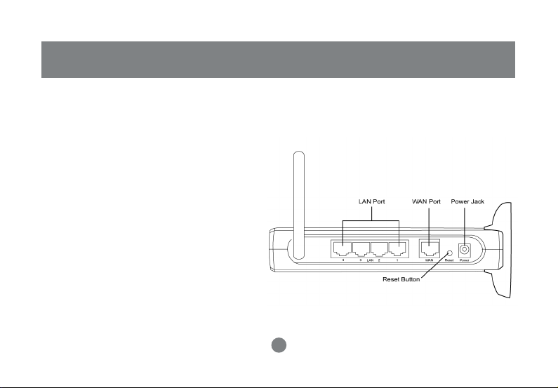
Pictorial Introduction
Back View
1. LAN ports: Ethernet Ports. Allows
connections of up to four computers or daisychain out to more hubs and switches.
2. WAN port: The WAN port is where you
connect your Cable or DSL modem through
an ethernet cable. It’s the only port that
connects to the Internet.
3. Reset button: The reset button can reboot the
router or set back to factory default setting.
Pess about 2 seconds to reboot the router;
press over 5 seconds to go back to factory
setting.
4. Power Jack: Power cable connection for 12V
adapter.
1
3
6
24
Page 10
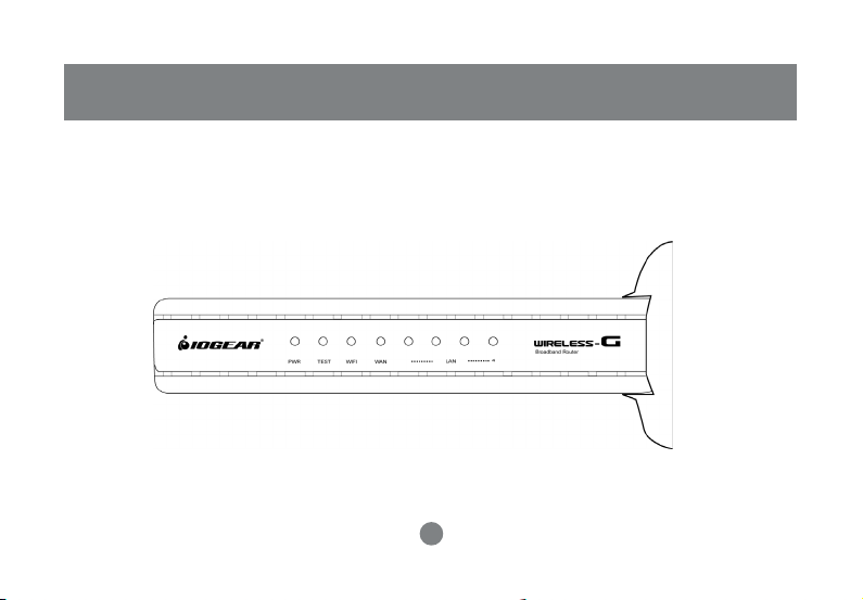
Front View
Pictorial Introduction
7
Page 11
Pictorial Introduction
8
Page 12
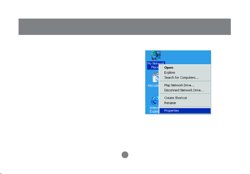
Configuring your PC
The instructions in this section will help you configure
each of your computers to be able to communicate
with the Wireless-G Broadband Router.
Note: The following screenshots are taken in
Windows 2000. For other OS, the configuration
procedure will be exactly the same but the
screenshots will vary.
1. Right-click mouse button on the My Network Place
icon on your Windows desktop and select
Properties from the short-cut menu.
Installation
9
Page 13
Installation
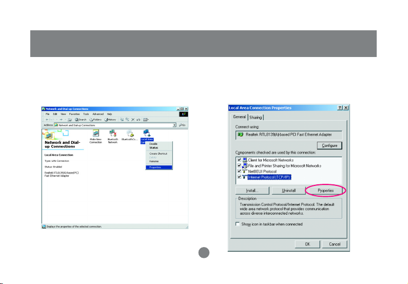
2. Right-click the Local Area Connection for the
Ethernet Adapter equipped on your computer and
select Properties from the shortcut menu.
3. Click the General tab of the Location Area
Connection dialog box, select Internet Protocol
(TCP/IP) and click Properties.
10
Page 14
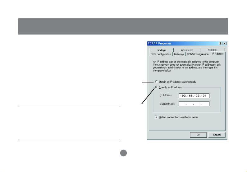
4. In the General tab, you can choose either obtain
an IP address automatically or Use the following IP
address.
• Enable DHCP: Click the button of Obtain an IP
address automatically.
• Use static IP address: Click the button of Use the
following IP address. For example, in the IP
address field, enter in the following IP address:
192.168.123.101.
Note: The default IP address of the router is
192.168.123. 254 so the IP address for the Ethernet
Adapter must follow the 192.168.123.x IP address
format and the IP should not be the same IP address
assigned to any other devices in the network.
11
Enable
DHCP
Function
Obtain
a Static ID
Installation
Page 15

Installation
5. Under Subnet mask, input the following IP address: 255.255.255.0.
6. Click OK to save your settings and close the dialog box.
12
Page 16
Quick Installation
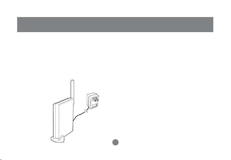
1. Take your IOGEAR® Wireless-G Broadband Router
out of box. Simply plug-in the included AC Adapter
to the wall outlet, then to the Broadband Router.
Make sure the power LED illuminates; otherwise,
try another AC Wall Outlet.
Note: If Antenna is detached, please make sure to
attach it properly to the back panel.
2. For initial setup, plug your desktop or notebook
computer directly into the LAN Port #1 with the
included CAT5 patch cable. Please make sure that
your computer LAN setting is DHCP or
192.168.123.x. Submask: 255.255.255.0
13
Page 17
Quick Installation
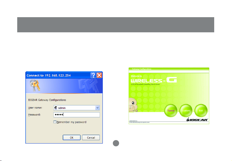
3. Open your Internet Browser (Internet Explorer,
Netscape, or Safari), and type in the following URL
in your browser’s address bar: 192.168.123.254.
You will be brought to Enter Network Password
prompt window. The default User Name is admin;
Password is admin.
4. To proceed to the basic setup options, click
on the Typical button.
14
Page 18
Quick Installation
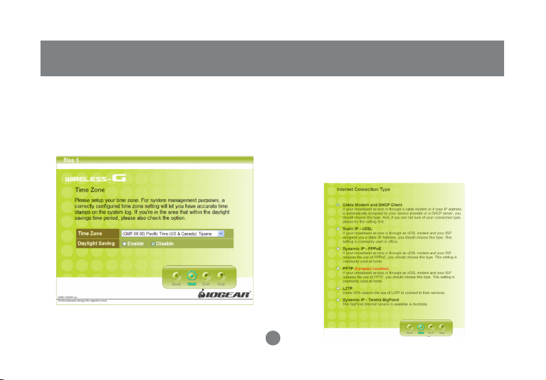
5. You will now be asked for the Time Zone you
are in. Select your Time Zone, and select
whether you wish to enable Daylight Savings
Time. Click Next to continue.
6. You will now be asked for which Inter net Connection
Type you are using. When you select the connection
type, you will be asked for your ISP’s configuration
settings. Cable Modem and DHCP Client is the most
common connection type, these instructions will be
based on this connection type. If you have a different
connection type, follow the instructions of your ISP
to configure its settings accordingly.
15
Page 19

Quick Installation
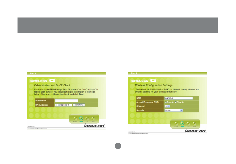
Cable Modem and DHCP Client
If your broadband access is through a cable
modem or if your IP address is automatically
assigned by your service provider or a DHCP
server, you should choose this type. And, if you are
not sure of your connection type, please try this
setting first.
Static IP - xDSL
If your broadband access is through an xDSL
modem and your ISP assigned you a static IP
Address, you should choose this type. This setting
is commonly used in office.
Dynamic IP - PPPoE
If your broadband access is through an xDSL
modem and your ISP requires the use of PPPoE,
you should choose this type. This setting is
commonly used at home.
PPTP (European Countries)
If your broadband access is through an xDSL modem
and your ISP requires the use of PPTP, you should
choose this type. This setting is commonly used at
home.
L2TP
Some ISPs require the use of L2TP to connect to their
services.
Dynamic IP - Telstra BigPond
The BigPond Internet service is available in Australia
16
Page 20
Quick Installation
After you have entered your ISP’s configuration
settings, click Next.
7. After you have entered your ISP’s configuration
settings, click Next.
8. You will now see the Wireless Configuration
Settings. You can set the SSID, channel, and
wireless security for your wireless gateway here.
Click Next when you are done. (For more
information on SSID, channel, and wireless
security, click on the Help button.)
17
Page 21
Quick Installation
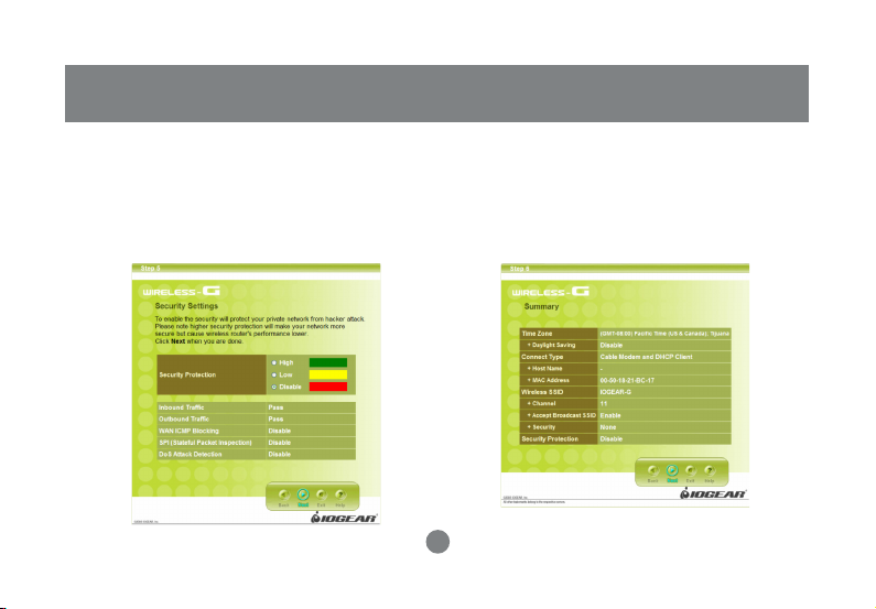
9. You will now see the Firewall settings. IOGEAR®
offers you an easy set-up package to configure a
Firewall. Please note high Firewall protection will
make your network securer, but may cause
wireless gateway’s performance to be lower. Click
Next when you are done.
10. This is the summary page showing all
configurations you’ve set. Click Next when you
are done.
18
Page 22

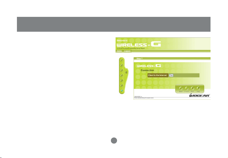
11. Click Finish when you are done. When you have
finished the configuration, you will be brought to
the main window.
Quick Installation
19
Page 23
Quick Installation
12. At this point your GWA504 router should be
working successfully and the router should be
giving access to the Internet to all the client
computers. To check the status of the router you
can click the Test button to see whether your
Internet connection is functioning.
Please make sure your WAN por t has been
connected (to a xDSL, Cable modem, or Ethernet).
Click Finish when you are done. When you have
finished the configuration, you will be brought to
the main window.
Note: The next steps show you Advanced Features
to enhance the configuration of your IOGEAR
GWA504 router
20
Page 24
Advanced Setup
Advanced Setup
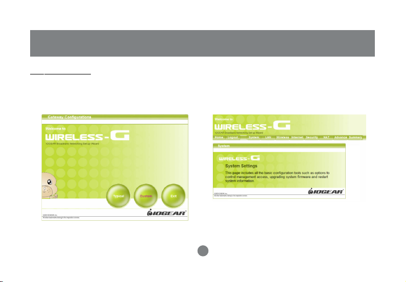
Step 1.
After you logged in as shown in Quick Installation
step 3, click on the Custom button.
Step 2.
The Customized Configuration menu is separated
into eight categories.
21
Page 25

Advanced Setup
System
It includes all the basic configuration tools, such
as options to control management access,
upgrading system firmware and restart system.
LAN
The router must have an IP address for the local
network. You can also enable DHCP service for
dynamic IP address allocation to your clients, or
configure filtering functions based on specific
clients or protocols.
Wireless
In this section, you can configure all wireless
related settings for your wireless access point.
Internet
In Internet settings, you can configure the way
your router connects to you ISP.
Security
Your Wireless-G Broadband Router features
powerful and flexible Firewall protection to keep your
network secure. You can configure the strength of
Firewall protection to a high or low level. If you are an
advanced user, you can configure Firewall policies to
meet on your needs.
NAT
Network Address Translation allows multiple users at
your local site to access the internet over a single
user account. It can also prevent hacker attacks by
mapping local addresses to public addresses for key
services such as Web or FTP.
Advance
Here you can set your log setting, SNMP, Routing,
Schedule Rule and Miscellaneous tasks.
Summary
In this section, you can check all system status,
network statistics and Event Log.
22
Page 26
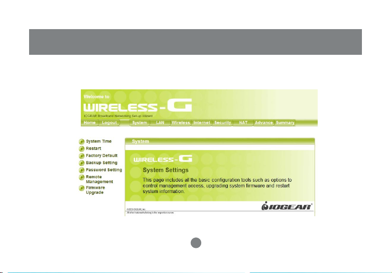
System Page
Configuration Utility
23
Page 27

Configuration Utility
System Time
For system management purposes, a correctly
configured time zone setting will let you have
accurate time stamps on the system log. If
you’re in an area that is within the daylight
savings time period, please also check the
option. You can also set device time manually or
consult network time from NTP server.
24
Page 28

Configuration Utility
Restart
In some special cases, you may restart your
Wireless-G Broadband Router manually without
unplugging the power cable. Please note that
restarting the Wireless-G Broadband Router you
will not lose your current configuration. Click
Restart button to restart the router.
Factory Default
Click the Reset to default button to set your
configuration back to factory settings.
25
Page 29

Configuration Utility
Backup Setting
Save the settings of your router to a file. Once you
want to restore these setting, click Firmware
upgrade and use the file you saved.
Password Setting
This is where you can change your administration
password for the Wireless-G Broadband Router. For
better security, you should give a new password
because password setting is disabled by default.
Don’t forget to Click Apply button to make your
configuration take effect.
26
Page 30

Remote Management
This setting allows you to manage your Wireless-G
Broadband Router through a WAN connection
(Internet). Click the button to enable or disable this
function. If you enable this function you can use the
specified port on your PC to remotely control the
router. The default port is 8080. You can also set
“Administration Time-out.” It is the amount of
inactivity before the device automatically close the
administration section. You can set “Administration
Time-out” to zero to disable it.
Configuration Utility
27
Page 31

Configuration Utility
Firmware Update
From time to time, a new and updated firmware will
be released, which has either feature improvements
or bug fixes. Once you download the new firmware
patch, you can update the firmware of your WirelessG Broadband Router from here.
• Upgrade Steps:
To update the firmware by web page, click the
Browse button first to select the file that had been
saved in your laptop or PC. Then click the Upgrade
button to update the firmware. Please do not power
off the router while upgrading and there will be a
sequence of screen descriptions to inform you the
status of the upgrade process. If the upgrade
process is successful, the utility will go back to
homepage.
28
Page 32

LAN Page
Configuration Utility
29
Page 33

Configuration Utility
IP Setting
You can setup IP address information for your
wireless router.
30
Page 34

DHCP Server
Your wireless router can act as a DHCP server, and
assign IP addresses to your clients automatically. This
function is enabled by default. The assigned IP
addressed will be within the range of IP pool that you
specify. It is a good security practice to set just enough
range of IP pool for the devices you want to connect to
this wireless network. This can block other unintended
devices to enter your network.
• IP Pool Starting Address: Enter a value for the
DHCP server to start with when issuing IP
addresses. The default value is 100.
• IP Pool Ending Address: The maximum number of
PCs that you want the DHCP server to assign IP
addresses to. This number cannot be greater than
253.
Configuration Utility
31
Page 35

Configuration Utility
DHCP Client
The DHCP client list shows clients assigned by the
DHCP server. Click Refresh button to refresh the list.
Wake-on-LAN is a technology that enables you to
power up a networked device remotely. In order to
enjoy this feature, the target device must be Wake-onLAN enabled. Click on the “Wake-up” button will
make the router to send the wake-up feature to the
target device immediately.
32
Page 36

Configuration Utility
MAC Filter
MAC Address Control allows you to assign different
access right for different users and to assign a
specific IP address to a certain MAC address.
MAC Address Control Check “Enable” to enable
the “MAC Address Control”. All of the settings in this
page will take effect only when “Enable” is checked.
Connection control Check “Connection control” to
enable the controlling of which wired andwireless
clients can connect to this device. If a client is
denied to connect to this device, it means the client
can’t access to the Internet either. Choose “allow” or
“deny” to allow or deny the clients, whose MAC
addresses are not in the “Control table” (please see
below), to connect to this device.
Association control Check “Association control” to
enable the controlling of which wireless client
canassociate to the wireless LAN. If a client is
denied to associate to the wireless LAN, it means
the client can’t send or receive any data via this
device. Choose “allow” or “deny” to allow or deny the
clients, whose MAC addresses are not in the
“Control table”, to associate to the wireless LAN.
“Control table” is the table at the bottom of the “MAC
Address Control” page. Each row of this table
indicates the MAC address and the expected IP
address mapping of a client. There are four columns
in this table:
MAC Address MAC address indicates a specific
client.
IP Address Expected IP address of the
corresponding client. Keep it empty if you don’t care
its IP address.
33
Page 37

Configuration Utility
C When “Connection control” is checked, check
“C” will allow the corresponding client to connect
to this device.
A When “Association control” is checked, check
“A” will allow the corresponding client to
associate to the wireless LAN. In this page, we
provide the following Combobox and button to
help you to input the MAC address.
You can select a specific client in the “DHCP
clients” Combobox, and then click on the “Copy
to” button to copy the MAC address of the client
you select to the ID selected in the “ID”
Combobox.
Previous page and Next Page To make this
setup page simple and clear, we have divided the
“Control table” into several pages. You can use
these buttons to navigate to different pages.
34
Page 38

Wireless Page
Configuration Utility
35
Page 39

Configuration Utility
SSID & Channel
Here is where you may modify the SSID and
Channel of your Wireless-G Broadband Router.
• SSID (Service Set ID, or Network Name):
Enter the name you wish to give your Wireless-G
Broadband Router (ex. “JOHN” or “IOGEAR”).
Every Wireless Clients (PC card, USB and PCI
adaptors) in your network must be configured to
accept with the same SSID.
• Channel
It can be left as Default, unless you plan on using
multiple access points. When multiple Wireless
Networks presenting, please ensure they are not
using the same channel, preferably at least 5
channels apart to each other.
36
Page 40

Configuration Utility
Authentication & Encryption
Select the data privacy algorithm you want. Enabling
the security can protect your data while it is
transferred from one station to another.
Disable : Disable the encryption feature.
WEP : Accept WEP clients only. WEP key must be
entered manually. You must input 10 Hexadecimal
digits for WEP 64 bit, or 26 Hexadecimal digits for
WEP 128 bit
• WEP Key 1, 2, 3 & 4
When you enable the 128 or 64 bit WEP key
security, please select one WEP key to be used
and input 26 or 10 hexadecimal (0, 1, 2...8, 9, A,
B...F) digits.
37
Page 41

Configuration Utility
802.1X : Accept normal clients and work
simultaneously with RADIUS Server. The
encryption key is got from RADIUS Server
dynamically.
• Encryption Key Length
You can select either 64 bits or 128 bits.
• RADIUS Server IP
The 802.1X server’s IP address.
• RADIUS port
The 802.1X server’s service port.
• RADIUS Shared Key
Key value shared by the RADIUS server and
this router. This key value is consistent with the
key value in the RADIUS server.
38
Page 42

WPA-PSK : Accept WPA clients only and Pre-share
key (encryption key) must be entered manually. You
can input either 8 to 63 ASCII characters or 64
Hexadecimal digits as Pre-share key.
• Pre-share Key Mode
Either ASCII or HEX can be selected.
• Pre-share Key
Please input either 8 to 63 ASCII characters
or 64 Hexadecimal digits as Pre-share key.
Configuration Utility
39
Page 43

Configuration Utility
WPA : Accept WPA clients only and work
simultaneously with RADIUS Server. The
encryption key is got from RADIUS Server
dynamically.
• RADIUS Server IP
The 802.1X server’s IP address.
• RADIUS port
The 802.1X server’s service port.
• RADIUS Shared Key
Key value shared by the RADIUS server and
this router. This key value is consistent with
the key value in the RADIUS server.
Note: If you enable 802.1X or WPA feature, you
must also have a RADIUS Server ready.
40
Page 44

Configuration Utility
Description:
• WEP Encryption: The WEP encr ypts frames
transmitted through wireless module using preentered WEP key. You can configure 4 key sets,
and select one of them to apply.
• WPA Encryption: Wi-Fi protected Access is
designed to improve Data protection and
implement access control for Wireless LAN
system. It encrypts frames transmitted through
wireless module using Pre-share key (PSK) or
the key got dynamically from RADIUS Server.
• 802.1X: When the 802.1X function is enabled, the
Wireless user must authenticate to this router first
to use the Network service. The most common
method of implementing 802.1X is by having a
RADIUS Server on your LAN containing an
authentication database, so the router can work
simultaneously with the server and get the user’s
authentication profile for comparison.
Note:
To complete the WPA operation, you also need to enable
the WPA client at the wireless client site (the computer
running wireless client’s devices, such as the GWP514
Cardbus card GWP514 Cardbus Card or GWU523 USB
adaptor).
Microsoft provides a free WPA upgrade for Windows XP
Service Pack 1 (SP1) and later or Windows Server 2003.
For any OS other than Win XP, there is client software
available from third-party suppliers such as Funk
Software’s Odyssey (www.funk.com).
The WPA client for Windows XP can be found in the
Microsoft Knowledge Base Article 815485
(http://support.microsoft.com/default.aspx?scid=kb;enus;815485) or downloaded directly from Microsoft
http://www.microsoft.com/downloads/
details.aspx?FamilyID=009d8425-ce2b-47a4-abec274845dc9e91&displaylang=en
41
Page 45

Configuration Utility
After installed, the Windows WPA Client will update
the wireless network configuration dialog boxes to
support new WPA options.
1. Click Connect To>Wireless Network Connection
to bring up the dialogue window of Wireless
Network Connection Status. Click the
Properties box to bring up next dialogue window.
2. In the Wireless Network Connection Properties
window, under Wireless Networks tab, please
check the box of “Use Windows to configure my
wireless network settings” to turn on the
Wireless Zero Configuration service. Select the
wireless access point you want to associate to,
then click Configure box at the right side to bring
up next dialogue window.
42
Page 46

Configuration Utility
3. Set up your WPA configuration by selecting the
Network Authentication mode and Data
encryption, and input same Network key as you
input at the Wireless-G Broadband Gateway.
Then, you are served by a more secured wireless
network
43
Page 47

Configuration Utility
Enhanced Setting
Authentication Type
If Shared Key is selected, the Access Point will not
be seen on the wireless network except to the
wireless clients which share the same WEP key as
the Access Point. If Open System is chosen, the
Access Point will be visible to all clients on the
network, but.only the wireless clients with the same
WEP key can to communicate on the wireless
network.
SSID broadcast
If the option is enabled, the SSID of the AP could be
seen in the site survey of wireless client’s utility. If
the option is disabled, the SSID of the AP will not be
seen in the wireless client’s utility.
Wireless Mode
11g only: The AP could let the 11g wireless clients
to connect only.
11b only: The AP could let the 11b and 11g wireless
clients to connect, but the 11g wireless clients will
connect the AP in 11b mode.
Mixed: The AP could let both 11b and 11g wireless
clients to connect
44
Page 48

Configuration Utility
WDS Setting
The Wireless Distribution System (WDS) provides
wireless point-to-point bridging, and point-tomultipoint bridging for deployment over large area.
With the WDS feature, the WLAN coverage range
can be easily extended.
Wireless Bridging
The wireless bridging feature can be enabled by
setting the mode to Enable. The default setting is
Disable, only access point function is available.
Once the Wireless Bridging is enabled, both
wireless bridging and wireless access point
functions are simutaneously available.
Remote AP MAC
Please enter the MAC Address of WDS-enabled AP.
Only autherized AP can access this router through
WDS feature to extend the WLAN coverage range.
Up to 3 AP’s MAC are allowed.
45
Page 49

Configuration Utility
Associated Client List
It displays information of stations that are
currently associated to your wireless router. You
can check who are linking to your network, for
security and activity monitoring purposes. Click
Refresh button to update the list.
46
Page 50

Configuration Utility
Internet Page
In Internet Settings, you can configure the way your Wireless-G Broadband Router uses to connect to your ISP.
47
Page 51

Configuration Utility
Connection Type
It allows you to configure the way you connect to your
ISP. This Wireless Broadband Router can be
connected to your ISP in any of the following ways:
DHCP Client, PPPoE, Static IP, L2TP and Dynamic IP.
• DHCP Client: Enter the Host Name if your
ISP provides it; otherwise, just leave it blank.
48
Page 52

Configuration Utility
• Dynamic IP - PPPoE: Complete User name,
password, confirm password fields.
• Static IP: Complete the IP address, subnet mask,
ISP gateway and primary DNS fields.
49
Page 53

Configuration Utility
• Dynamic IP - PPTP: Complete fields on this screen.
Those information can get from your ISP.
50
Page 54

MAC Clone
If your ISP restricts connections to pre-registered
computers only, use the MAC Clone feature to copy
your computer’s Media Access Control (MAC) address
to your wireless broadband router. This procedure will
cause the Wireless-G Broadband Router to appear as
a single computer.
To do MAC Clone: click Clone MAC.
Configuration Utility
51
Page 55

Configuration Utility
Virtual Computers
Virtual Computer enables you to use the original
NAT feature, and allows you to setup the one-toone mapping of multiple global IP address and local
IP address.
•
Global IP:
by your ISP.
•
Local IP
PC corresponding to the global IP address.
•
Enable
Computer feature
Enter the global IP address assigned
: Enter the local IP address of your LAN
: Check this item to enable the Virtual
52
Page 56

Dynamic DNS
This feature enables you to run your domain (ex.
www.mywebsite.com) over a changing IP. Before you
can use this feature, you need to sign up for DDNS
service from one of the Dynamic DNS providers that
this Wireless-G Broadband Router supports and fill
in related fields to make it work. You may follow the
following steps to enable this function.
• Sign up for DDNS service and write down the host
name, user name and password.
• Click the radio button of Enable to enable the
dynamic DNS function.
• Complete the host name, user name and password
fields.
• Click Save button to update the information. Click
the radio button of Disable to disable this function.
Configuration Utility
53
Page 57

Configuration Utility
Security
Your IOGEAR Wireless-G Broadband Router features powerful and flexible firewall protection to keep your
computer and/or network secure.
If you are an advanced user, you can configure firewall policies depending on your needs.
54
Page 58

Packet Filter
Packet Filter enables you to control what packets
are allowed to pass the router.
Outbound filter applies on all outbound packets.
However, Inbound filter applies on packets that
destined to Virtual Servers or DMZ host only.
You can select one of the two filtering policies:
1. Allow all to pass except those match the specified
rules
2. Deny all to pass except those match the specified
rules
Configuration Utility
55
Page 59

Configuration Utility
You can specify 8 rules for each directions: inbound
or outbound.
For each rule, you can define the following:
• Source IP address
• Source port address
• Destination IP address
• Destination port address
• Protocol: TCP or UDP or both.
For source or destination IP address, you can define
a single IP address (4.3.2.1) or a range of IP
addresses (4.3.2.1-4.3.2.254). An empty implies all
IP addresses.
For source or destination port, you can define a
single port (80) or a range of ports (1000-1999). Add
prefix “T” or “U” to specify TCP or UDP protocol. For
example, T80, U53, U2000-2999. No prefix indicates
both TCP and UDP are defined. An empty implies all
port addresses.
Each rule can be enabled or disabled individually.
Use Rule#
Choose the schedule when you want to make this
service take effect, and select the ID you want to use
with the schedule rule. Then click “Copy to” botton to
copy it into the “Use rule #” box to use the schedule.
When choosing rule 0 for always, it is the same as
not using schedule.
56
Page 60

Schedule example
Assume that there is a rule setting
in Rule 1 which is Everyday
17:30~24:00, and there is a FTP
server which IP is 192.168.123.5
and listening port 21. The Virtual
Server’s setting is as below:
Description:
It means the WAN users can’t
access this FTP server only at
17:30~24:00 everyday. If the time
exceeds this range, the WAN users
can access the LAN FTP server.
Configuration Utility
57
Page 61

Configuration Utility
Domain Filter
Domain Filter let you prevent users under this device
from accessing specific URLs.
Domain Filter Enable
Check
if you want to enable Domain Filter.
Log DNS Query
Check
if you want to log the action when someone
accesses the specific URLs.
Privilege IP Addresses Range
Setting a group of hosts and privilege these hosts to
access network without restriction.
Domain Suffix
A suffix of URL to be restricted. For example, “.com”,
“xxx.com”.
Action
When someone is accessing the URL met the
domain-suffix, what kind of action you want.
Check
drop to block the access.
these access.
Enable
Select “Enable” to enable each rule.
Check
log to log
58
Page 62

URL Blocking
URL Blocking will block Lan computers to connect to
pre-defined Websites.
URL Blocking Enable
Check
if you want to enable URL Blocking.
URL
If any part of the Website’s URL matches the predefined word, the connection will be blocked.
For example, you can use pre-defined word “sex” to
block all websites if their URLs contain pre-defined
word “sex”.
Enable
Select “Enable” to enable each rule.
Configuration Utility
59
Page 63

Configuration Utility
DMZ
DMZ (DeMilitarized Zone) Host is a host without the
protection of firewall. It allows a computer to be
exposed to unrestricted 2-way communication for
Internet games, Video conferencing, Internet
telephony and other special applications.
Note: This feature should be used only when needed
.
60
Page 64

Miscellaneous
WAN ICMP Blocking
When this feature is enabled, any host on the WAN
cannot ping this product.
SPI Mode
When this feature is enabled, the router will record
the packet information pass through the router like
IP address, port address, ACK, SEQ number and so
on. And the router will check every incoming packet
to detect if this packet is valid.
DoS Attack Detection
When this feature is enabled, the router will detect
and log the DoS attack comes from the Internet.
Currently, the router can detect the following DoS
attack: SYN Attack, WinNuke, Port Scan, Ping of
Death, Land Attack etc.
Configuration Utility
61
Page 65

Configuration Utility
NAT Page
Network Address Translation allows multiple computers on your network to access the Internet over a single
user account. NAT can also prevent hacker attacks by mapping local addresses to public addresses for key
services such as Web or FTP.
62
Page 66

Configuration Utility
Virtual Server
You can configure the Wireless-G Broadband Router
as a virtual server so that remote users can access
services such as Web or FTP at your local site via
public IP addresses.
Virtual Server enables WWW, FTP and other
services on your LAN to be accessible to Internet
users. Refer
Example
Comment
The above example provides 4 type of ser vices: FTP
Server (port 21), Web Server (port 80), PPTP VPN
Server (port 1723, PPTP) and a user defined server
(ports 2000-2999).
63
Internet Services for well known ports.
Page 67

Configuration Utility
Use rule #
Choose the schedule when you want to make this
service take effect, and select the ID you want to
use with the schedule rule. Then click “Copy to”
botton to copy it into the “Use rule #” box to use the
schedule. When choosing r ule 0 for always, it is the
same as not using schedule.
Schedule example
Assume that there is a rule setting in Rule 1 which
is Everyday 8:30~17:30, and there is a FTP server
which IP is 192.168.123.15 listening port 21. The
Virtual Server’s setting is as below:
Description:
It means the WAN users can access this FTP
server only at 08:30~17:30 everyday. If the time
exceeds this range, the WAN users can’t access
the LAN FTP server.
64
Page 68

Special Applications
Some applications require multiple connections, like
Internet games, Video conferencing, Internet
telephony and so on. Due to the firewall function,
these applications can not work with pure NAT
Configuration Utility
router.
Special Applications
applications to work with NAT router. The settings
are:
This product provides some predefined settings.
Select your application and click
predefined setting to your list. If the mechanism of
Special Applications
work, try DMZ host instead.
NOTE: At any time, only one PC can use each
Special Application
65
makes some of these
Copy to
fails to make an application to
.
to add the
Page 69

Configuration Utility
Log Setting
This page support two methods to export system
logs to specific destination by means of
syslog(UDP) and SMTP(TCP). The items you have
to setup including:
IP Address for Syslogd
Host IP of destination where syslogs will be sent to.
Check
Enable to enable this function.
E-mail Alert Enable
Check if you want to enable Email alert(send syslog
via email).
SMTP Server IP and Port
Input the SMTP server IP and port, which are
concated with ‘:’. If you do not specify port number,
the default value is 25.
For example,”192.168.1.100:26".
66
Page 70

Send E-mail alert to
The recipients who will receive these logs. You can
assign more than 1 recipient, using ‘;’ or ‘,’ to
separate these email addresses.
E-mail Subject
The subject of email alert. This setting is optional.
Username and Password
To fill some SMTP ser ver’s authentication
requirement, you may need to input Username and
Password that offered by your ISP.
Configuration Utility
67
Page 71

Configuration Utility
SNMP
Enable SNMP
You must check either Local or Remote or both to
enable SNMP function. If
device will response request from LAN. If
checked, this device will response request from
WAN.
Get Community
Setting the community of GetRequest your device
will response.
Set Community
Setting the community of SetRequest your device
will accept.
Local
is checked, this
Remote
is
68
Page 72

Routing
Routing Table settings are used to setup the
functions of static routing.
Static Routing
For static routing, you can specify up to 8 routing
rules. You can enter the destination IP address,
subnet mask, gateway, hop for each routing rule, and
then enable or disable the rule by checking or
unchecking the Enable checkbox.
Configuration Utility
69
Page 73

Configuration Utility
Schedule Rule
Select
if you want to Enable the Scheduler.
Edit
To edit the schedule rule.
Delete
To delete the schedule rule, and the rule# of the
rules behind the deleted one will decrease one
automatically.
Add New Rule
Click “Add New Rule” to enter “Schedule Rule
Setting” page to increase a new schedule rule.
70
Page 74

UNP Setting
UPnP is short for Universal Plug and Play which is
designed to simplify device and network service
installation and management.If you enable this
function,the router will work with UPnP devices/
softwares.
Configuration Utility
71
Page 75

Configuration Utility
Miscellaneous
Non-standard FTP port
You have to configure this item if you want to access
an FTP server whose port number is not 21.
setting will be lost after rebooting.
MAC Address for Wake-on-LAN
Wake-on-LAN is a technology that enables you to
power up a networked device remotely. In order to
enjoy this feature, the target device must be Wakeon-LAN enabled and you have to know the MAC
address of this device, say 00-11-22-33-44-55.
Clicking “Wake up” button will make the router to
send the wake-up frame to the target device
immediately.
Ping Test
Allow you to configure an IP address or a Domain
Name, and ping the device. You can ping a secific IP
to test whether it is alive.
This
72
Page 76

Summary Page
This page includes all the basic configuration of the Broadband Router.
73
Configuration Utility
Page 77

Configuration Utility
System Status Statistic
You can view the status of your Wireless-G
Broadband Router from this window. The system
status of the router is divided into four sections:
General information, Internet Settings, LAN Settings
and Wireless Settings. Click Refresh button to update
all information.
List the data transmission status of the router. Click
Refresh button to update statistics.
74
Page 78

Event Log
You can view any/all system events
sent through your network from this
window. Click Refresh button to
update the list.
Configuration Utility
75
Page 79

Specification
76
Page 80

Specification
77
Page 81

Technical Support
If you need technical support, please check out our IOGEAR Tech Info Library (T.I.L.) at
www.iogear.com/support for the latest tips, tricks, and troubleshooting. The IOGEAR T.I.L.
was designed to provide you with the latest technical information about our products. Most of
the answers to your questions can be found here, so please try it out before contacting
technical support.
Technical suppor t is available Monday through Friday from 8:00 am to 5:00 pm PST and can
be reached at 866-946-4327 or by email support@iogear.com.
78
Page 82

Radio & TV Interference Statement
WARNING!!! This equipment generates, uses and can radiate radio frequency energy and, if
not installed and used in accordance with the instruction manual, may cause interference to
radio communications. This equipment has been tested and found to comply with the limits for
a Class B computing device pursuant to Subpart J of Part 15 of FCC Rules, which are
designed to provide reasonable protection against such interference when operated in a
commercial environment. Operation of this equipment in a residential area is likely to cause
interference, in which case the user at his own expense will be required to take whatever
measures may be required to correct the interference.
79
Page 83

Limited Warranty
IN NO EVENT SHALL THE DIRECT VENDOR’S LIABILITY FOR DIRECT, INDIRECT,
SPECIAL, INCIDENTAL OR CONSEQUENTIAL DAMAGES RESULTING FROM THE USE OF
THE PRODUCT, DISK OR ITS DOCUMENTATION EXCEED THE PRICE PAID FOR THE
PRODUCT.
The direct vendor makes no warranty or representation, expressed, implied, or statutory with
respect to the contents or use of this documentation, and especially disclaims its quality,
performance, merchantability, or fitness for any particular purpose.
The direct vendor also reserves the right to revise or update the device or documentation
without obligation to notify any individual or entity of such revisions, or updates. For further
inquires please contact your direct vendor.
80
Page 84

Regulatory Compliance FCC Warning
This device complies with Part 15 of the FCC Rules.
Operation is subject to the following two conditions: (1) this device may not cause harmful interference, and (2)
this device must accept any interference received, including interference that may cause undesired operation.
This equipment has been tested and found to comply with the limits for a Class B digital device, pursuant to
part 15 of the FCC Rules. These limits are designed to provide reasonable protection against harmful
interference in a residential installation.
This equipment generates, uses and can radiate radio frequency energy and, if not installed and used in
accordance with the instructions, may cause harmful interference to radio communications. However, there is
no guarantee that interference will not occur in a particular installation. If this equipment does cause harmful
interference to radio or television reception, which can be determined by turning the equipment off and on, the
user is encouraged to try to correct the interference by one or more of the following measures:
• Reorient or relocate the receiving antenna.
• Increase the separation between the equipment and receiver.
• Connect the equipment into an outlet on a circuit different from that to which the receiver is connected.
• Consult the dealer or an experienced radio/TV technician for help.
Changes or modifications not expressly approved by the party responsible for compliance could void your
authority to operate the equipment.
1) To comply with FCC RF exposure compliance requirements, a separation distance of at least 20 cm must
be maintained between the antenna of this device and all persons.
2) This transmitter must not be co-located or operating in conjunction with any other antenna or transmitter.
81
Page 85

®
Contact info.
23 Hubble • Irvine, CA 92618 • (P) 949.453.8782 • (F) 949.453.8785 • www.iogear.com
 Loading...