

Page 1

Wireless-G Broadband Router
User Manual (GWA502)
®
®
Page 2

Page 3

Welcome
Thank you for choosing IOGEAR® to serve your wireless needs. Soon, you will be sharing files
or surfing the Internet wirelessly. We hope you will have as much fun using your IOGEAR
®
Wireless-G Broadband Router, as we had designing it.
Rest assured, your IOGEAR® Wireless-G Broadband Router is built rock-solid to ensure
maximum up-time for you to stay up-and-running. If for any reason you have a problem, we
stand behind our products with an industry-leading 3 year factory warranty, so you can have
peace-of-mind with your current and future IOGEAR® purchases.
We want you to be happy with your purchase, so we have made every effort to ensure product
quality, reliability, and ease-of-use.
©2004 IOGEAR. All Rights Reserved. PKG-M0108
IOGEAR®, the IOGEAR® logo, are trademarks or registered trademarks of IOGEAR®, Inc. Microsoft and Windows are
registered trademarks of Microsoft® Corporation. IBM is a registered trademark of International Business Machines, Inc.
Macintosh, G3/G4 and iMac are registered trademarks of Apple Computer, Inc. IOGEAR® makes no warranty of any kind with
regards to the information presented in this document. All information furnished here is for informational purposes only and is
subject to change without notice. IOGEAR®, Inc. assumes no responsibility for any inaccuracies or errors that may appear in
this document.
Page 4

Table of Contents
Package Contents
Introduction
Features
Requirements
○○○○○○○○○○○○○○○○○○○○○○○○○○○○○○○○
○○○○○○○○○○○○○○○○○○○○○○○○○○○○○○○○○
○○○○○○○○○○○○○○○○○○○○○○○○○○○○○○○
Pictorial Introduction
Installation
○○○○○○○○○○○○○○○○○○○○○○○○○○○○○○○○
Quick Installation
Configuration Utility
- System Page
- LAN Page
- Wireless Page
- Internet Page
- Firewall Page
○○○○○○○○○○○○○○○○○○○○○○○○○○○○○○
○○○○○○○○○○○○○○○○○○○○○○○○○○○○○○○○
○○○○○○○○○○○○○○○○○○○○○○○○○○○○○○
○○○○○○○○○○○○○○○○○○○○○○○○○○○○○○○
○○○○○○○○○○○○○○○○○○○○○○○○○○○○○○
○○○○○○○○○○○○○○○○○○○○○○○○○○○○○
○○○○○○○○○○○○○○○○○○○○○○○○○○○○
○○○○○○○○○○○○○○○○○○○○○○○○○○○○○
○○○○○○○○○○○○○○○○○○○○○○○○○○○○
03
04
05
06
07
10
14
22
23
28
33
46
52
Page 5

Table of Contents
- NAT Page
- Summary Page
Specification
Technical Support
○○○○○○○○○○○○○○○○○○○○○○○○○○○○○○○○○
○○○○○○○○○○○○○○○○○○○○○○○○○○○○○○
○○○○○○○○○○○○○○○○○○○○○○○○○○○○○○○○
○○○○○○○○○○○○○○○○○○○○○○○○○○○○○
Radio and TV Interference Statement
Limited Warranty
○○○○○○○○○○○○○○○○○○○○○○○○○○○○○
Regulatory Compliance FCC Warning
○○○○○○○○○○○○○○○○○○○○○
○○○○○○○○○○○○○○○○○○○○
2
57
59
62
64
65
66
67
Page 6

Package Contents
This package contains:
• IOGEAR Wireless-G Broadband Router
• Category-5 Ethernet Patch Cable
• AC Po wer Adapter
• Quick Start Guide
• User Manual CD
• Warranty & Registration Card
3
Page 7

Introduction
IOGEAR’s Ultra-F ast Wireless-G Broadband Router is an all-in-one wireless access point, router , and 4-port
Ethernet switch for both small and home office users. With IOGEAR, you can surf the Internet, share files, and
chat with your friends....Wirelessly!
Our simple, easy-to-use, web-based setup wizard will have you up-and-running in minutes.
Moreover, our turn-ke y Firew all and Wireless Security packages keep y ou saf e on the Internet.
Remember, IOGEAR’ s Wireless Broadband Router giv es y ou the same connectivity and security that big
companies use...all in a small, cost-effective, reliable setup . Go with IOGEAR, and go Wireless!
4
Page 8

Features
Features
• Built-in…
- 4-port 10/100 Base T Ethernet Switch
- Internet Router
- Wireless Access Point
• 802.11g and 802.11b Compliant
• Advanced Wireless Security P ac kage
- Wireless Protected Access (W AP)
- Wired Equivalent Privacy (WEP)
- MAC and IP Address Filtering
• Built-in High-Gain Directional Antenna —— Super signal transceiving
• NAT and SPI FireWall
• Solid Three Y ear Limited Warranty
5
Page 9

System Requirements
• PC system
- 200MHz or faster CPU
- Internet browser
- Microsoft Windows 98/ME/2000/XP
- Ethernet interface card or WLAN client card installed
• Mac system
- G3 Power Mac or higher
- Mac OS 9.2 and above
- Open Ethernet Prot or Airport card installed
Requirements
6
Page 10
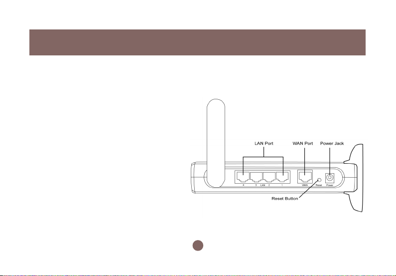
Pictorial Introduction
Back View
1. LAN ports: Ethernet P orts. Allows
connections of up to four computers or daisychain out to more hubs and switches.
2. W AN port: The WAN port is where you
connect your Cable or DSL modem through
an ethernet cable. It’s the only port that
connects to the Internet.
3. Reset button: The reset b utton can reboot the
router or set back to factory default setting.
Pess about 2 seconds to reboot the router;
press over 5 seconds to go back to factory
setting.
4. Po wer Jack: Po wer cable connection for 12V
adapter.
1
3
7
24
Page 11
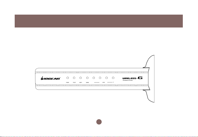
Front View
Pictorial Introduction
8
Page 12
Pictorial Introduction
Front View
9
Page 13
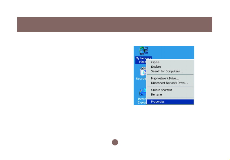
Configuring your PC
The instructions in this section will help you configure
each of your computers to be able to communicate
with the Wireless-G Broadband Router.
Note: The follo wing screenshots are taken in
Windows 2000. F or other OS, the configuration
procedure will be exactly the same but the
screenshots will vary.
1. Right-click mouse b utton on the My Netw ork Place
icon on your Windows desktop and select
Properties from the short-cut menu.
Installation
10
Page 14
Installation
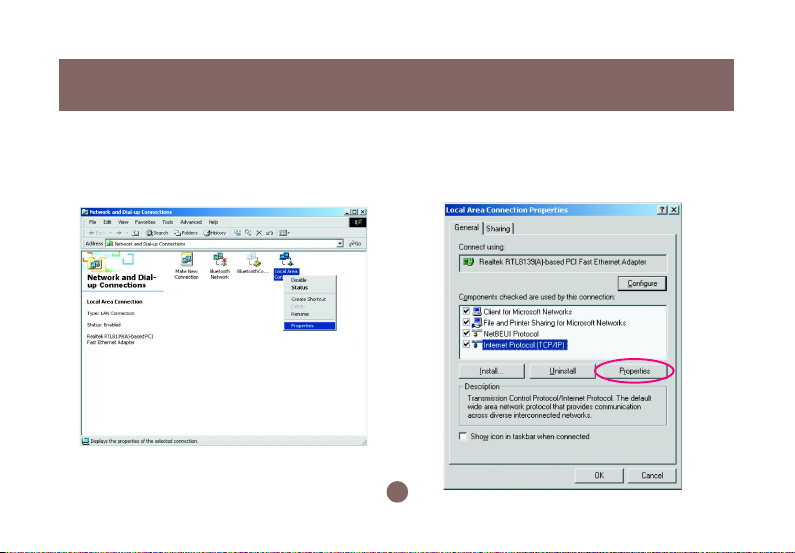
2. Right-click the Local Area Connection for the
Ethernet Adapter equipped on your computer and
select Properties from the shortcut menu.
3. Click the General tab of the Location Area
Connection dialog box, select Internet Protocol
(TCP/IP) and click Properties.
11
Page 15
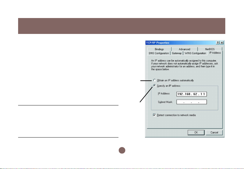
4. In the General tab, you can choose either obtain
an IP address automatically or Use the following IP
address.
• Enable DHCP: Click the b utton of Obtain an IP
address automatically.
• Use static IP address: Clic k the b utton of Use the
following IP address. F or e xample, in the IP
address field, enter in the following IP address:
192.168.62.11.
Note: The def ault IP address of the router is
192.168.62.10 so the IP address for the Ethernet
Adapter must follow the 192.168.62.x IP address
format and the IP should not be the same IP address
assigned to any other devices in the network.
12
Enable
DHCP
Function
Obtain
a Static
ID
Installation
Page 16

Installation
5. Under Subnet mask, input the follo wing IP address: 255.255.255.0.
6. Click OK to save your settings and close the dialog box.
13
Page 17
Quick Installation
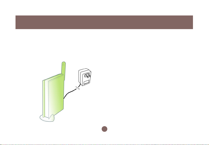
1. Tak e your IOGEAR® Wireless-G Broadband Router
out of box. Simply plug-in the included AC Adapter
to the wall outlet, then to the Broadband Router.
Make sure the power LED illuminates; otherwise ,
try another AC Wall Outlet.
2. F or initial setup , plug your desktop or notebook
computer directly into the LAN Port #1 with the
included CA T5 patch cab le. Please mak e sure
that your computer LAN setting is DHCP or
192.168.62.x. Submask: 255.255.255.0.
14
Page 18
Quick Installation
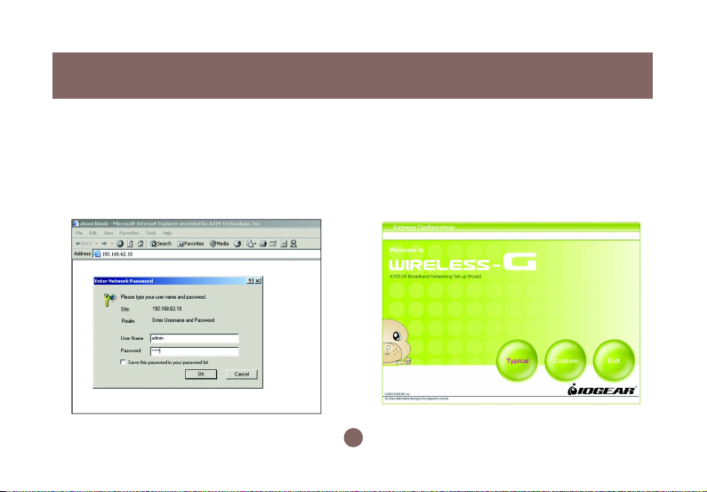
3. Open your Internet Browser (Internet Explorer,
Netscape, or Safari), and type in the following URL
in your browser’s address bar: 192.168.62.10. You
will be brought to Enter Network Password
prompt window. The default User Name is admin;
Password is admin .
4. To proceed to the basic setup options, clic k
on the Typical button.
15
Page 19
Quick Installation
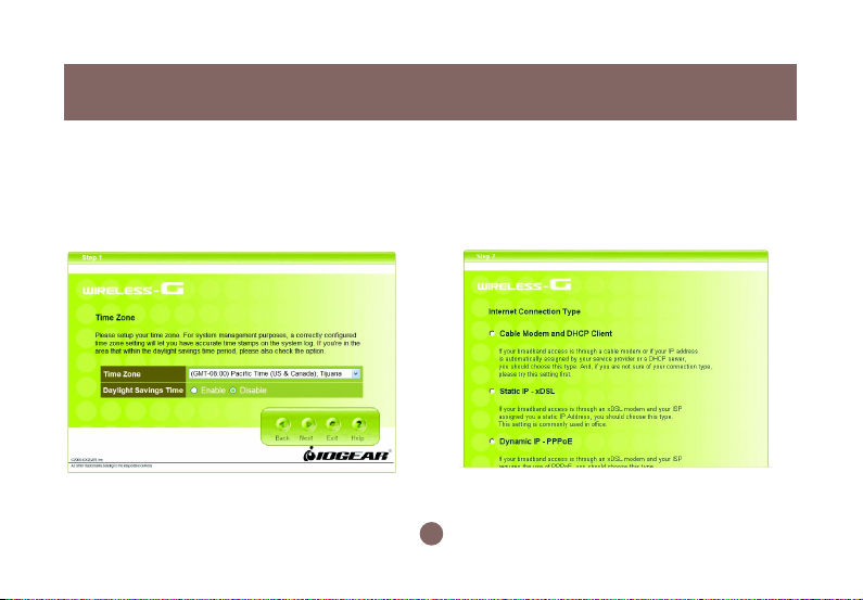
5. You will now be ask ed f or the Time Zone you
are in. Select your Time Zone, and select
whether you wish to enable Daylight Savings
Time. Clic k Next to continue.
6. You will now be asked f or which Internet
Connection Type you are using. When you
select the connection type, you will be asked for
your ISP’s configuration settings (if applicable).
16
Page 20

Quick Installation
a. Cable Modem and DHCP Client - If y our broadband
access is through a cable modem, or if your IP
address is automatically assigned by your service
provider or a DHCP server, you should choose this
type.
• If your ISP gave you a Host Name or a MAC
address, you can enter them on the following
page.
b. Static IP - xDSL - If your broadband access is
through an xDSL modem and your ISP assigned
you a static IP Address, you should choose this type.
• Please enter the necessary information such as
the IP Address, Subnet Mask, Default Gatewa y
and DNS server that your ISP provided in the
following page.
c. Dynamic IP - If your broadband access is through
an xDSL modem and your ISP did not assign you a
static IP Address, you should choose this type.
• Please enter the necessary information such as
username and password your ISP provided in the
following page. If your ISP gave you a service
name, you should enter it in the following page.
d . Dynamic IP (Eur opean countries) - If your
broadband access is through an xDSL modem and
your ISP did not assign you a static IP Address,
you should choose this type.
• If your Internet Service Provider requires the use
of PPTP, enter the information. (PPTP is generally
more popular in Europe.)
After you have entered your ISP’s configuration
settings, click Next.
17
Page 21
Quick Installation
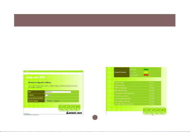
7. You will now see the Wireless Configuration
Settings. You can set the SSID, channel, and
wireless security for your wireless gatewa y here .
Click Next when you are done.
(For more information on SSID , channel, and
wireless security, y ou can mo ve the mouse cursor
over the highlighted feature and an explanation will
appear.)
8. You will now see the Firew all settings. IOGEAR®
offers you an easy set-up package to configure a
Firewall. Please note high Firew all protection will
make your network securer, but ma y cause
wireless gateway’ s performance to be lower . Click
Next when you are done.
18
Page 22
Quick Installation
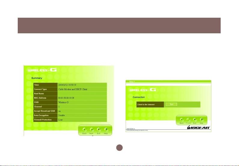
This is the summary page showing all
9.
configurations you’ve set. Clic k Next
when you are done.
10. You can click the test button to see whether
your Internet connection is functioning. Please
make sure your WAN port has been connected
(to a xDSL, Cable modem, or Ethernet). Click
Finish when you are done. When you have
finished the configuration, you will be brought to
the main window.
19
Page 23

Advanced Setup
After going through all the steps in Typical Configuration, your wireless router is ready to connect to your
ISP and allow internal clients to access to the Internet.
If you want to customize your wireless router for
specific purposes, you may perform the configuration
in this section.
1. Log-in to your Wireless Broadband Router
(Default as http://192.168.62.10)
2. You will now be asked for User Name and
Password. Unless you hav e changed them, they
should be default as admin (user name); admin
(Password).
Quick Installation
20
Page 24

Quick Installation
3. After you have logged in, click on the Custom
button.
4. The Customized Configuration menu is separated
into seven categories.
21
Page 25

Configuration Utility
System
LAN
Wireless
Internet
Firewall
NA T
Summary
It includes all the basic configuration tools, such as options to control management access,
upgrading system firmware and restart system.
The router must have an IP address for the local network. You can also enable DHCP service for
dynamic IP address allocation to your clients, or configure filtering functions based on specific
clients or protocols.
In this section, you can configure all wireless related settings for your wireless access point.
In Internet settings, you can configure the way your router connects to you ISP.
Y our Wireless-G Broadband Router f eatures po werful and flexib le Firew all protection to keep your
network secure. You can configure the strength of Firew all protection to a high or lo w lev el. If you
are an advanced user, y ou can configure Firewall policies to meet on y our needs .
Network Address Translation allows multiple users at your local site to access the internet over a
single user account. It can also prevent hac k er attac ks by mapping local addresses to pub lic
addresses for key services such as W eb or FTP.
In this section, you can check all system status, network statistics and Event Log.
22
Page 26

Configuration Utility
System Page
23
Page 27

Configuration Utility
Time Zone
For system management purposes, a correctly
configured time zone setting will let you have accurate
time stamps on the system log. If you’ re in an area that
is within the daylight savings time period, please also
check the option.
Restart
In some special cases, you may restart your
Wireless-G Broadband Router manually without
unplugging the power cable. Please note that
restarting the Wireless-G Broadband Router you
will not lose your current configuration. Click
Restart button to restart the router.
24
Page 28

Configuration Utility
Click the Restore button to set your configuration
back to factory settings.
Password SettingFactory Default
This is where you can change your administration
password for the Wireless-G Broadband Router . For
better security, y ou should giv e a new pass word
because password setting is disabled by def ault.
Don’t forget to Click Apply button to make y our
configuration take effect.
25
Page 29

Remote Management
This setting allows you to manage your Wireless-G
Broadband Router through a WAN connection
(Internet). Click the button to enable or disab le this
function. If you enable this function y ou can use the
specified port on your PC to remotely control the
router. The def ault port is 8080.
Configuration Utility
26
Page 30

Configuration Utility
Firmware Update
From time to time, a new and updated firmware will
be released, which has either feature improvements
or bug fixes. Once y ou download the new firmware
patch, you can update the firmware of your WirelessG Broadband Router from here.
• Upgrade Steps:
T o update the firmware by web page, clic k the
Browse button first to select the file that had been
saved in your laptop or PC . Then click the Upgrade
button to update the firmware. Please do not power
off the router while upgrading and there will be a
sequence of screen descriptions to inform you the
status of the upgrade process. If the upg rade
process is successful, the utility will go back to
homepage.
27
Page 31

LAN Page
Configuration Utility
28
Page 32

Configuration Utility
IP Setting
You can setup IP address information for the LAN
ports of your wireless router.
DHCP Server
Your wireless router can act as a DHCP server , and
assign IP addresses to your clients automatically . This
function is enabled by default. The assigned IP
addressed will be within the range of IP pool that you
specify . It is a good security practice to set just enough
range of IP pool for the devices y ou want to connect to
this wireless network. This can bloc k other unintended
devices to enter your network.
• IP Pool Starting Address: Enter a v alue for the
DHCP server to start with when issuing IP
addresses. The default v alue is 192.168.62.12.
• IP P ool Ending Address: The maximum number of
PCs that you want the DHCP server to assign IP
addresses to. This number cannot be greater than
253.
29
Page 33

• Lease Time: Setting Lease Time f or shorter period,
such as one day or several hours , can free up IP
addresses frequently . How ev er , you ma y
experience brief network performance drag down or
stall when DHCP reassigning IP addresses to
clients. It also causes a computer’ s IP address
changed over time. If y ou will use some adv anced
router features, such as DMZ or client IP filters, you
may select longer time to avoid frequent re-set, or
you can use Static Host setting described below.
Configuration Utility
30
Page 34

Configuration Utility
DHCP IP MAC Mapping
This setting will permanently associate the MAC
address of a LAN client to an IP address. The client
is assigned the same IP address every time.
Changes to a currently assigned LAN client IP will
take effect only after expiration of current lease. T o
create a new association, enter the information on
the field and click Add button. To delete an
association, press Delete button on the list.
DHCP Client
The DHCP client list shows clients assigned by the
DHCP server. Click Refresh button to refresh the list.
31
Page 35

Configuration Utility
MAC Filter
You can control which PCs can connect to the
Internet. If you enable this f eature, only computers
with a MAC address located in MAC List can connect
to the Internet.
T o add a MA C address , enter the MA C address in the
MAC address field, specify Allow or Deny and click
Add button. Clic k Delete button will delete a MA C
Address.
IP Filter
You can control which PCs can connect to the
Internet. If you enable this f eature, only computers
with an IP address located in IP List can connect to
the Internet. To add an IP address, click the radio
button of Allow, type the IP address and click Add.
The allowed IP address will be added. To delete an IP
address, click Delete button on the list.
32
Page 36

Configuration Utility
Wireless Page
33
Page 37

SSID & Channel
Here is where you may modify the SSID and
Channel of your Wireless-G Broadband Router .
• SSID (Service Set ID, or Network Name):
Enter the name you wish to give your Wireless-G
Broadband Router (ex. “JOHN” or “IOGEAR”).
Every Wireless Clients (PC card, USB and PCI
adaptors) in your network must be configured to
accept with the same SSID.
• Channel
It can be left as Default, unless you plan on using
multiple access points. When multiple Wireless
Networks presenting, please ensure they are not
using the same channel, preferably at least 5
channels apart to each other.
Configuration Utility
• Accept Broadcast SSID
By broadcasting SSID, all wireless de vices at
surrounding area can see your wireless router and
easy to associate with it. How ev er, it is a good
security practice not to broadcast SSID, just
configure SSID info to those client devices you w ant
them to access you network.
34
Page 38

Configuration Utility
Authentication & Encryption
It allows you to configure the setting of network
authentication and data encryption.
• Network A uthentication:
Y ou can specify the authentication type .
- “Both” allows wireless client de vices access
your router no matter with shared key or not.
- “Share Key” only allows devices with same
WEP (Wired Equivalent Privacy) key to
access your wireless router.
- “802.1X” and “WPA” require you to type in
Radius server IP and server key. Please
check with your Network Administrator for
related information.
- “WPA-PSK” needs a pre-shared key to be set
on your wireless router and all wireless client
devices.
35
Page 39

• Encryption:
- WEP Configuration
Configuration Utility
Click the drop-down menu to select WEP to enab le
the WEP function and select 64 bits or 128 bits. The
128 bits gives a higher level of security. The
selection must be the same between all connected
network devices. F or 64-bit WEP key, it should be
five ASCII characters (a-z and 0-9, for example:
gear56) or ten hexadecimal digits in length (a
through f, and 0 through 9, for example:
2af30bc9d5); for 128 bit WEP k e y, the length will be
13 characters for ASCII or 26 digits for Hexadecimal.
WEP keys 1-4 enable you to create an encryption
scheme for wireless LAN transmissions.
36
Page 40

Configuration Utility
WP A and WP A-PSK configuration
Wi-Fi Protected Access (WPA) is a sub-set of the
forthcoming IEEE 802.11i security standard. WPA
addresses those known weakness of WEP and
provides stronger security to wireless network.
IOGEAR Wireless-G Broadband Router supports
three authentication modes:
• 802.11x (need RADIUS server to authenticate
the clients, using WEP keying)
• WPA (same 802.1x, but with TKIP keying
support); WPA-PSK (Pre-Shared Key , no
RADIUS server needed)
- WP A-PSK
37
Page 41

Configuration Utility
There are two ways to configure W PA Pre-Shared Key:
1. PassPhrase Mode: Input a phrase into the field.
The Wireless-G Broadband Router will automatically generate a Pre-Shared Key based on the
phrase you enter. The phrase can be within 8 to 63
characters (we recommend at least 12 characters
to achieve a sufficient lev el of security).
2. Hex mode: Input 64 he xadecimal digits. Please
write down the key you enter. You will need to enter
same key to your wireless client side.
WP A Group Rekey Interv al
This router could change the group key periodically .
Enter the period you want into the WPA Group Rekey
Interval field.
Encryption Type
The current version only supports TKIP encryption.
AES encryption will be available soon.
- WPA
38
Page 42

Configuration Utility
RADIUS Server IP
Please enter the IP address of RADIUS server
RADIUS Server Port
This field specifies the port on which RADIUS server
is listening.
RADIUS Server Key
This field carries the shared secret for RADIUS
authentication. Some information need to be
encrypted in a RADIUS packet, this key is used to
encrypt and decrypt this information (such as
password).
Reconfirm RADIUS Server Key
Make sure RADIUS Server Key is correct.
WP A Group Rekey Interv al
It is the same as WPA-PSK configuration
Encryption Type
It is the same WPA-PSK configuration
Note:
To complete the WPA operation, you also need to enable the
WPA client at the wireless client site (the computer running
wireless client’s devices, such as the GWP511 Cardbus card
GWP512 Cardbus Card or GWU513 USB adaptor).
Microsoft provides a free WPA upgrade for Windows XP
Service Pack 1 (SP1) and later or Windows Server 2003. For
any OS other than Win XP, there is client software available
from third-party suppliers such as Funk Software’s Odyssey
(www.funk.com). IOGEAR’s GWP512 Wireless-G Network PC
Card has it built-in.
The WPA client for Windows XP can be found in the Microsoft
Knowledge Base Article 815485 (http://support.microsoft.com/
default.aspx?scid=kb;en-us;815485) or downloaded directly
from Microsoft http://www.microsoft.com/downloads/
details.aspx?FamilyID=009d8425-ce2b-47a4-abec274845dc9e91&displaylang=en
39
Page 43

After installed, the Windows WPA Client will update the
wireless network configuration dialog boxes to support new
WP A options.
1. Click Connect T o>Wireless Network Connection
to bring up the dialogue window of Wireless
Network Connection Status. Clic k the
Properties box to bring up next dialogue window .
2. In the Wireless Network Connection Properties
window, under Wireless Networks tab , please
check the box of “Use Windows to configure my
wireless network settings” to turn on the
Wireless Zero Configuration service. Select the
wireless access point you want to associate to,
then click Configure box at the right side to bring
up next dialogue window .
Configuration Utility
40
Page 44

Configuration Utility
3. Set up your WPA configuration by selecting the
Network Authentication mode and Data
encryption, and input same Network key as you
input at the Wireless-G Broadband Gatewa y .
Then, you are served by a more secured wireless
network
41
Page 45

Configuration Utility
Radio Setting
Here you can configure Wireless radio settings .
Please note that these settings are for advanced users
or network administrators. If you are unf amiliar with
how to configure these parameters, we recommend
that you keep them at their default value .
• Mode: The Wireless-G Broadband Router can be set
at three wireless modes: A uto , 802.11g only and
802.11b only . If both 802.11g and 802.11b clients
presenting at your network, please select “Auto”
mode (This is default mode). “802.11g only” mode
only supports 802.11g clients, and gives better
performance to whole network. Howe ver , all 802.11b
clients will not be able to use your network at this
mode setting. In some situation, 802.11b clients with
old drivers cannot work with Auto mode; “802.11b
only” mode can accommodate this problem, but
decrease the performance of 802.11g devices.
42
Page 46

Configuration Utility
• Beacon Period: Beacons are pack ets sent b y the
router to synchronize a wireless network. The v alue
of beacon interval is depending on the environment
where the router is operating. Specify a Beacon
interval value between 1 and 1000(units: ms). The
default value is set to 100 milliseconds, i.e., ten
beacons per second.
• RTS Threshold: The R TS threshold is the pac k et size
at which packet transmission is gov erned by the
RTS/CTS transaction. Each station can ha v e a
different RTS threshold. If you encounter inconsistent
data flow, only minor modifications are recommended. The default v alue f or RTS Threshold is set
to 2347.
• Fragment Threshold: This v alue should remain at its
default setting of 2346. If you e xperience a high
packet error rate, you ma y modify slightly y our
“Fragmentation” v alue within the value r ange of 800
to 2346. Setting the F ragmentation v alue too low ma y
result in poor performance.
• DTIM Period: Enter a v alue between 1 and 255 f or
the Delivery Traffic Indication Message (DTIM). A
DTIM is a countdown informing clients of the next
window for listening to broadcast and multicast
messages. When the router has b uffered broadcast
or multicast messages for associated clients, it
sends the next DTIM with a DTIM Interval value. Its
clients hear the beacons and awaken to receive
the broadcast and multicast messages. The def ault
value for DTIM interval is set to 1.
43
Page 47

Association Control
This page allows you to control which computers
can connect to the Wireless-G Broadband Router.
If you enable this feature, only computers with a
MAC address listed located in Association
Control List can connect to the wireless LAN.
Configuration Utility
To add an association, enter the MAC address in the
address field, specify Allow or Deny attribute and click
Add button.
T o delete an association, clic k Delete b utton from the
Association Client List.
44
Page 48

Configuration Utility
Associated Client List
It displays information of stations that are
currently associated to your wireless router. Y ou
can check who are linking to your network, for
security and activity monitoring purposes. Click
Refresh button to update the list.
45
Page 49

Configuration Utility
Internet Page
In Internet Settings, you can configure the way your Wireless-G Broadband Router uses to connect to your ISP.
46
Page 50

Configuration Utility
Connection Type
It allows you to configure the way y ou connect to your
ISP. This Wireless Broadband Router can be
connected to your ISP in any of the following w a ys:
DHCP Client, PPPoE, Static IP and PPTP
• DHCP Client: Enter the Host Name if your
ISP provides it; otherwise , just leav e it b lank.
47
Page 51

Configuration Utility
• Dynamic IP - PPPoE: Complete User name,
password, confirm password fields.
• Static IP: Complete the IP address, subnet mask,
ISP gateway and primary DNS fields.
48
Page 52

Configuration Utility
• Dynamic IP - PPTP: Complete fields on this screen.
Those information can get from your ISP.
49
Page 53

MAC Clone
If your ISP restricts connections to pre-registered
computers only , use the MA C Clone f eature to copy
your computer’s Media Access Control (MA C) address
to your wireless broadband router. This procedure will
cause the Wireless-G Broadband Router to appear as
a single computer.
T o do MAC Clone: clic k Clone MAC A utomatically.
Configuration Utility
50
Page 54

Configuration Utility
Dynamic DNS
This feature enables you to run your domain (ex .
www.mywebsite.com) o ver a changing IP. Bef ore y ou
can use this feature, you need to sign up f or DDNS
service from one of the Dynamic DNS providers that
this Wireless-G Broadband Router supports and fill in
related fields to make it work. Y ou may follow the
following steps to enable this function.
• Sign up for DDNS service and write down the host
name, user name and password.
• Click the radio button of Enable to enable the
dynamic DNS function.
• Complete the host name, user name and password
fields.
• Click Update Now button to update the information.
Click the radio button of Disable to disable this
function.
51
Page 55

Configuration Utility
Firewall Page
Your IOGEAR Wireless-G Broadband Router features powerful and flexible fire wall protection to k eep your
computer and/or network secure.
You can configure the strength of firewall protection at a high or low level. If y ou are an adv anced user, you
can configure firewall policies depending on your needs.
52
Page 56

Configuration Utility
Basic Setting
Configure the basic settings to enable the firewall to
protect your network from hacker attack s. Choose
High, Low or Disable button will enable its
corresponding settings.
Please be careful on these configurations. Any
incorrect settings might cause the firewall to block all
traffic or make your network vulnerable to outside
hacker attacks.
53
Page 57

Service Filter
Configuration Utility
You can add custom service filters not listed in the
services tables. Select any added custom service
filters in the Policies section to enable adv anced
firewall settings.
Name field: Enter the name you wish to give to any
application.
Protocol: Click the drop-down menu to select TCP or
UDP protocol.
Port range: Check the application’ s documentation
and enter the port range.
Descriptions: Describe the application.
54
Page 58

Configuration Utility
Some of the popular applications and protocol/port numbers settings are defined below:
55
Page 59

Configuration Utility
Policies
Policies are rules that you define for y our firewall
settings. You ma y define rules, f or e xample, for
inbound and outbound traffic.
Virtual DMZ
If you have a local client computer that cannot run
an Internet application properly from behind the
NA T firewall, you can open the client up to
unrestricted two-way Internet access by defining
a Virtual DMZ.
56
Page 60

Configuration Utility
NAT Page
Network Address Translation allows multiple computers on your network to access the Internet over a single
user account. NAT can also prevent hacker attac ks by mapping local addresses to pub lic addresses f or k ey
services such as Web or FTP.
57
Page 61

Virtual Server Virtual Server
You can configure the Wireless-G Broadband Router
as a virtual server so that remote users can access
services such as Web or FTP at your local site via
public IP addresses.
For example: a FTP server (public port 21) will be
translated into a local site (private 192.168.1.25)
through private port 1502.
Special Applications such as Internet gaming, video
conferencing, and Internet telephony software usually
require multiple connections. The Special Applications
feature allows these applications to work properly .
58
Configuration Utility
Page 62

Configuration Utility
Summary Page
This page includes all the basic configuration of the Broadband Router.
59
Page 63

System Status Statistic
You can view the status of your Wireless-G
Broadband Router from this window. The system
status of the router is divided into four sections:
General information, Internet Settings, LAN Settings
and Wireless Settings. Click Refresh button to update
all information.
List the data transmission status of the router. Click
Refresh button to update statistics.
60
Configuration Utility
Page 64

Configuration Utility
Event Log
You can view any/all system events
sent through your network from this
window. Clic k Refresh button to
update the list.
61
Page 65

Specification
62
Page 66

Specification
63
Page 67

Technical Support
If you need technical support, please check out our IOGEAR Tech Info Library (T.I.L.) at
www.iogear.com/support for the latest tips, tricks, and troubleshooting. The IOGEAR T.I.L.
was designed to provide you with the latest technical information about our products. Most of
the answers to your questions can be found here, so please try it out before contacting technical
support.
Technical support is available Monday through Friday from 8:00 am to 5:00 pm PST and can be
reached at (949) 453-8782 or by email support@iogear.com.
64
Page 68

Radio & TV Interference Statement
WARNING!!! This equipment generates, uses and can radiate radio frequency energy and, if
not installed and used in accordance with the instruction manual, may cause interference to
radio communications. This equipment has been tested and found to comply with the limits for
a Class B computing device pursuant to Subpart J of Part 15 of FCC Rules, which are designed
to provide reasonable protection against such interference when operated in a commercial
environment. Operation of this equipment in a residential area is likely to cause interference, in
which case the user at his own expense will be required to take whatever measures may be
required to correct the interference.
65
Page 69

Limited Warranty
IN NO EVENT SHALL THE DIRECT VENDOR’S LIABILITY FOR DIRECT, INDIRECT,
SPECIAL, INCIDENTAL OR CONSEQUENTIAL DAMAGES RESULTING FROM THE USE OF
THE PRODUCT, DISK OR ITS DOCUMENTATION EXCEED THE PRICE PAID FOR THE
PRODUCT.
The direct vendor makes no warranty or representation, expressed, implied, or statutory with
respect to the contents or use of this documentation, and especially disclaims its quality,
performance, merchantability, or fitness for any particular purpose.
The direct vendor also reserves the right to revise or update the device or documentation
without obligation to notify any individual or entity of such revisions, or updates. For further
inquires please contact your direct vendor.
66
Page 70

Regulatory Compliance FCC Warning
This device complies with Part 15 of the FCC Rules.
Operation is subject to the following two conditions: (1) this de vice ma y not cause harmful interference, and (2)
this device must accept any interference receiv ed, including interference that ma y cause undesired operation.
This equipment has been tested and found to comply with the limits for a Class B digital de vice, pursuant to
part 15 of the FCC Rules. These limits are designed to pro vide reasonable protection against harmful
interference in a residential installation.
This equipment generates, uses and can radiate radio frequency energy and, if not installed and used in
accordance with the instructions, may cause harmful interference to radio communications. Howe v er , there is
no guarantee that interference will not occur in a particular installation. If this equipment does cause harmful
interference to radio or television reception, which can be determined by turning the equipment off and on, the
user is encouraged to try to correct the interference by one or more of the following measures:
• Reorient or relocate the receiving antenna.
• Increase the separation between the equipment and receiver.
• Connect the equipment into an outlet on a circuit different from that to which the receiver is connected.
• Consult the dealer or an experienced radio/TV technician for help.
Changes or modifications not expressly approved by the party responsible for compliance could v oid y our
authority to operate the equipment.
1) To comply with FCC RF exposure compliance requirements, a separation distance of at least 20 cm must
be maintained between the antenna of this device and all persons.
2) This transmitter must not be co-located or operating in conjunction with any other antenna or transmitter.
67
Page 71

Page 72

®
Contact info.
23 Hubble • Irvine, CA 92618 • (P) 949.453.8782 • (F) 949.453.8785 • www.iogear.com
 Loading...