

Page 1

Quick Start Guide
HD A / V Cat 5e/6 Extender
PART NO. Q1185
GVE320
Page 2

Package Contents
2 x HDMI Extender (1 Sender & 1 Receiver)
2 x Power Adapter
2 x Wall Mount Kit
1 x Quick Start Guide
1 x Warranty Card
Requirements
Media Source
• 1 HDMI output
Display
• 1 HDMI input
Cables
• 2 Identical solid Cat 5e/6 cables
• 2 HDMI cables
Specifications
Device Connections 1 N/A
Connectors
Switches EQ Adjustment N/A 1 x 8-position switch
LEDs
HDMI Resolution
Power Consumption DC5V,1.22W DC5V,0.95W
Environment
Physical
Properties
* The specifications and pictures are subject to change without notice.
Function Sender Receiver
Display HDMI Out N/A
Device HDMI In
Unit to Unit 2 x RJ-45 Female 2 x RJ-45 Female
Power Jack 1 x DC Jack 1 x DC Jack
Power Orange Orange
On Line N/A Green
Operation Temp. 32-122°F
Storage Temp. -4°-140°F
Humidity 0-80% RH, Non-condensing
Housing Metal
Weight 0.35 lb
Dimensions 3.54 x 2.17 x 0.94 in
1 x HDMI Type A 19-pin
Female
HDTV resolutions: 480p, 720p, 1080i. 1080p
(1920 x 1080); PC resolutions: VGA, SVGA,
XGA, SXGA, UXGA, WUXGA (1920 x 1200)
Up to 130ft. for 1080p; 200ft. for 1080i
1 x HDMI Type A 19-pin
Female
N/A
Page 3
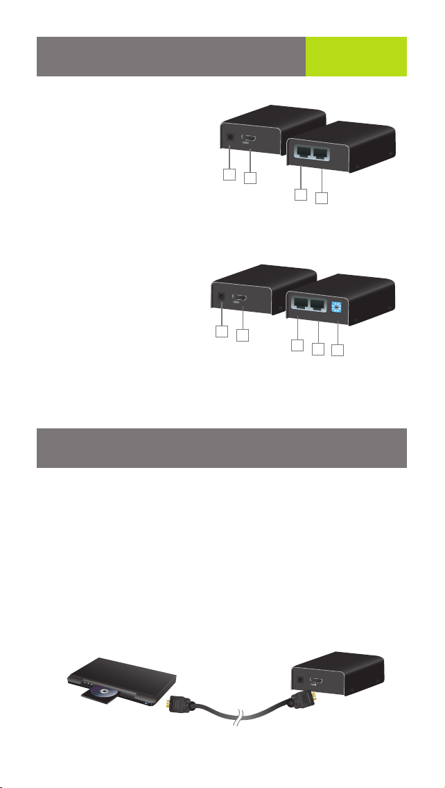
Overview
Start Here!
Sender unit
1. Power Jack
2. HDMI In
3. TMDS* Port
4. DDC** Port
Front
1
Back
IN
TMDS DDC
2
3
4
Receiver unit
1. Power Jack
2. HDMI Out
3. TMDS* Port
4. DDC** Port
5. Equalization (EQ)
Adjustment Switch
Front
1
Back
OUT
2
TMDS DDC
3
EQ
4
5
* Transition Minimized Differential Signaling (TMDS)
**Display Data Channel (DDC)
Installation
Preparation
Before you connect the extender kit, please connect your media source and
display unit directly with a HDMI cable and adjust the proper resolution
settings accordingly. Refer to your devices’ user manuals for more details.
Please power off both units before you start the extender installation.
STEP 1
Connect one end of the HDMI cable to your media source’s output and
connect the other end to the HDMI In port of the sender unit of the HDMI
Extender.
Media Source
Sender unit
IN
Page 4

STEP 2
Connect one end of the HDMI cable to your display unit’s input and connect
the other end to the HDMI Out port of the receiver unit of the HDMI Extender.
Display
Receiver unit
OUT
STEP 3
Plug in one of the Cat 5e/6 cables to DDC of both sender and receiver unit
of the HDMI Extenders. Make sure the connection is not loose.
Sender unit
TMDS DDC
TMDS DDC
Receiver unit
EQ
STEP 4
Plug in the second Cat 5e/6 cable to TMDS of both sender and receiver
unit of the HDMI Extenders. Make sure the connection is not loose.
Receiver unitSender unit
TMDS DDC
TMDS DDC
EQ
Page 5

STEP 5
Plug the power adapter between the wall outlet and the sender unit. Then
plug the other power between the wall outlet and the receiver unit.
Sender unit
IN
Receiver unit
OUT
FINAL STEP
Turn on your media source and display. If you don't see any audio/video or the
quality is not good, follow the steps below to adjust the EQ setting, or lower
the resolution settings as indicated in the Preparation section.
*Note: Extension range may vary with different devices and Cat 5e/6 cables
Equalization (EQ) Adjustment Switch
The EQ switch allows you to fine tune the video quality of your setup to
avoid any video flickering or blinking. You may start with EQ level 0 and
increase until you see the optimized video. Wait for couple seconds
between each setting for proper adjustment.
LED Indication
LED Local Unit Remote Unit
Power Orange Orange
Online N/A Green
Description
The unit is powered
The TMDS signal is sending from
the sender unit and received by
the receiver unit properly
Page 6

Rack Mount (Optional)
1. Screw the rack mount ears onto the bottom of the unit with the provided
screws.
2. Then screw the unit onto the rack by using
M4 x 6 Philips head screws (not included).
HDMI IN
Page 7

FCC Statement
This product has been tested and found to comply with the limits for a
Class A digital device, pursuant to Part 15 of the FCC Rules. These limits
are designed to provide reasonable protection against harmful radio
frequency interference when operated in a commercial environment. See
User Manual for additional information.
CE Compliance
This device has been tested and found to comply with the following
European Union directives: Electromagnetic Capability (89/336/EMC), Low
Voltage (73/23/EEC) and R&TTED (1999/5/EC).
Limited Warranty
WE’RE HERE TO HELP YOU!
NEED ASSISTANCE SETTING UP THIS PRODUCT?
Make sure you:
1. Use the live chat at www.iogear.com to try and solve any issues you may be
having with the product
2. Visit the Tech Info Library/FAQ on www.iogear.com (under the Support tab)
3. Call the tech support line at 1-866-946-4327 (U.S. only) or 1-949-453-8782
Warranty Information
This product carries a 3 Year Limited Warranty. For the terms and conditions of
this warranty, please go to http://www.iogear.com/support/warranty or
call 1-866-946-4327
Register online at http://www.iogear.com/register
Important Product Information
Product Model
Serial Number
Contact
IOGEAR
Address: 19641 Da Vinci, Foothill Ranch, CA 92618 USA
Toll Free: 866-9-IOGEAR
Phone: 949-453-8782
Web site: www.iogear.com
Email: support@iogear.com
Page 8

About UsAbout Us
FUN
IOGEAR offers connectivity solutions that are innovative, fun, and
stylish, helping people enjoy daily life using our high technology
products.
GREEN
IOGEAR is an environmentally conscious company that emphasizes the importance of conserving natural resources. The use of
our technology solutions helps reduce electronic waste.
© 2011 IOGEAR
®
 Loading...