

Page 1

User Manual
4Kx2K 4-Port HD Switch
GHSW8241
PART NO. M1293-a
www.iogear.com
Page 2

Page 3

Table of Contents
Introduction 4
Package Contents 5
Requirements 5
Overview 6
Installation 7
Port Switching 8
Serial Port (RS-232) Conguration 9
Serial Port (RS-232) Conguration List 10
Powering Off and Restarting 16
Specication 17
Compliance Information 18
Limited Warranty 19
Contact 19
3
Page 4

Introduction
IOGEAR’s 4Kx2K 4-Port HD Switch allows users to connect up to four HD
source devices to one HD display and supports Ultra HD 4Kx2K, the latest
digital format for high-denition displays at a distance of up to 50ft. For easy
access and convenience, this switch has one HD port on the front panel
that can be used to connect your portable devices, such as laptops, tablets
or digital cameras, while the other three HD ports on the back provide
permanent connections for your Blu-ray players, set-top boxes, game
consoles and more.
Switching between source devices can be done via the front panel push-
buttons, RS-232 bi-directional control or IR remote control with front panel
LEDs indicators for each source device. The built-in bi-directional RS-232
serial port allows you to control the switch through a high-end controller, PC
and / or home automation / home theater software system.
4
Page 5

Package Contents
1 x GHSW8241 4Kx2K 4-Port HD Switch
1 x HD Cable
1 x IR Remote Control
Requirements
Source Devices
• HD output
Display
• HDTV or HD Projector with an HD input
Cables
• 4 HD Cables*
• RS-232 Cable (optional)*
• IR extension Cable (optional)*
*Cable not included
1 x Power Adapter
1 x Quick Start Guide
1 x Warranty Card
5
Page 6
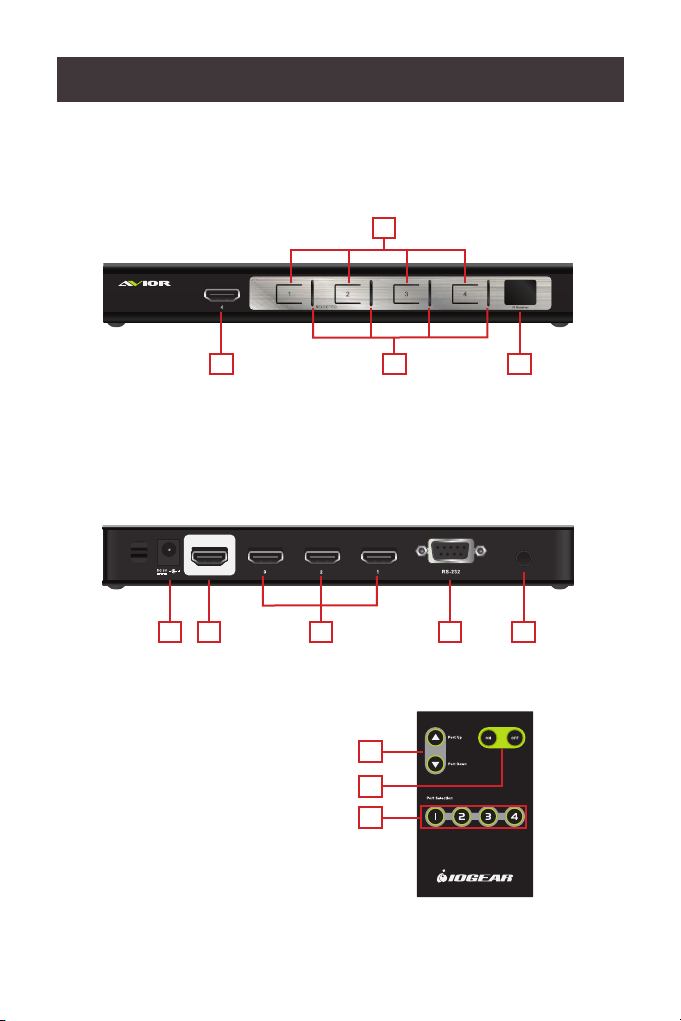
Overview
Power
IR EXT
HD OUTPUT
HD INPUT HD INPUT
HD INPUT
Power
Front View
1. HD Input
2. Port Selection Push-button
HD INPUT
3. Port Status LED
4. IR Receiver
2
1
3
4
Back View
1. Power Jack
2. HD Output
3. HD Input
HD OUTPUT
HD INPUT HD INPUT
1
2 4 5
4. RS-232 Serial Port
5. IR Extension Port
(IR extension cable not included)
HD INPUT
3
IR EXT
Remote Control
1. Port Up / Port Down Buttons
2. Power ON / OFF
(see note below)
3. Port Selection Buttons
1
2
Power
3
Note: The remote in this manual covers multiple models and some features
may not work on all models.
6
Page 7

Installation
Note: Make sure your source devices and display are powered off
before you start.
STEP 1
Connect an HD cable to the output port from the HD switch to the input port
of the HDTV or HD Projector.
STEP 2
Connect any HD media sources to the input ports of the HD switch via HD
cables.
STEP 3 (optional)
Connect your hardware or software RS-232 controller for HD switch control.
STEP 4 (optional)
If you have an IR extension cable (not included), plug it into the IR
Extension port and place it where the IR remote can reach it.
STEP 5
Connect the power adapter to the power jack and into an available wall
outlet.
HD OUTPUT
HD INPUT HD INPUT
HD INPUT
IR EXT
STEP 5
STEP 1
STEP 2
7
STEP 3
STEP 4
Control
processor
PS4
Page 8

Port Switching
Via Front Panel Pushbutton
• Press the specic Port ID’s push-button to switch your media source.
Via IR Remote Control
• Press the specic port ID’s button to switch your media source.
• Press the Port Up / Down buttons to switch to the previous or next port
respectively.
*Note: The maximum range of the remote control is 20ft. Aim the remote
control at the IR receiver located on the front panel of the 4Kx2K 4-Port HD
Switch. For optimal performance, make sure there is a clear line-of-sight
between the remote control and the IR receiver.
Via RS-232 hardware or software device
• Please refer to the serial port conguration and command list on
pages 9-10 for more details.
8
Page 9

Serial Port (RS-232) Conguration
The device’s built-in bi-directional RS-232 serial interface allows system
control through a high-end controller, PC and / or home automation / home
theater software package.
Conguring the Serial Port
The controller’s serial port should be congured as follows:
Description Setting
Baud Rate 19200
Data Bits 8
Parity None
Stop Bits 1
Flow Control None
Verication
After entering a command, using the instructions on pages 10-15, a
verication message will appear:
• Command OK – indicates that the command is correct and successfully
performed by the switch
• Command incorrect – indicates that the command has the wrong format
and / or values
9
Page 10

Serial Port (RS-232) Conguration List
Switch Port Commands
The formulas for Switch Port commands are as follows:
1. Switch Command + Input Command + Port Number + [Enter]
- For example, to switch to input port 02, type the following:
sw i02 [Enter]
2. Switch Command + Enable / Disable HD Out + [Enter]
- For example, to disable the HD output signal, type the following:
sw off [Enter]
3. Switch Command + Port Sequence (+ / -) + [Enter]
- For example, to switch to the next input port (+), type the following:
sw + [Enter]
Note: Each command string can be separated with a [Space].
The following tables show the possible values and formats for the
Switch Port formulas:
Command Description
sw Switch Command
Input Description
i Input Command
Port Number Description
xx 01-04 (default is 01)
Control Description
on Enable HD Output Signal
off Disable HD Output Signal
+ Port Sequence – Next Port
- Port Sequence – Previous Port
10
Page 11

The following table lists the available Switch Port Commands:
Command Input Port # Control Enter Description
[Enter] Switch Input Port
on [Enter] Turn on (Display on)
sw i xx
off [Enter] Turn off (Display off)
+ [Enter] Switch to the next input
- [Enter]
Switch to the previous
input
Read Command
To view the current conguration settings of the device, enter in the formula
as follows:
1. Read Command + [Enter]: read [Enter]
The following table shows the value for the Read formula:
Command Description
read Read information from the device
Reset Command
To reset the device back to the factory default settings, enter in the formula
as follows:
1. Reset Command + [Enter]: reset [Enter]
The following table shows the value for the Reset formula:
Command Description
reset Reset the device back to factory default
11
Page 12

Switch Mode Command
You can choose how the 4Kx2K 4-Port HD Switch behaves when a new
input source is connected. There are three Switch Modes:
1. Default – The switch behaves normally without automatic switching.
2. Next – Switch priority is placed on the next port that has a new source
device connected to it.
3. Auto – Places priority on a selected port so that when a source is
connected to the selected port, the 4Kx2K 4-Port HD Switch will
automatically switch to it, and the port cannot be changed until the
source device is unplugged or auto switching mode is disabled with the
default command.
4. In addition, the Go To function enables the 4Kx2K 4-Port HD Switch
to switch to the next port with a powered on source device when the
current input source device is powered off.
12
Page 13

The formulas for Switch Mode Commands are as follows:
1. Switch Command + Input Command + Port Number + Control [Enter]
- For example, to enable Auto Mode for port 02, type the following:
swmode i02 auto [Enter]
2. Switch Command + Control [Enter]
- For example, to enable Next Mode, type the following: swmode next
[Enter]
3. Switch Command + Control [Enter]
- For example, to enable Default Mode to disable Next / Auto mode,
type the following: swmode default [Enter]
4. Switch Command + Control [Enter}
- For example, to enable the Go To function, type the following:
swmode goto on [Enter]
The following tables show the possible values and formats for the Switch
Mode Command formulas:
Command Description
swmode Switch Mode Command
Input Description
i Input Command
Port Number Description
xx 01-04 (default is 01)
Control Description
default No automatic switching
next Priority is placed on the next port that has a new source
connected to it (default setting)
auto Priority is placed on a selected port
goto on Switch to the next port with a powered on source device
when the current input source is off
goto off Disable Go To (default setting)
13
Page 14

The following table lists the available Switch Mode Commands:
Command Input Port # Control Enter Description
default [Enter] To use the Default
Switch Mode
next [Enter] To use the Next Switch
Mode
swmode
i xx auto [Enter] To use the Auto Switch
Mode for port #
goto on [Enter] To enable the Go To
function
goto off [Enter] To disable the Go To
function
Hot Plug Detect Command
When enabled, Hot Plug Detect (HPD) will force the connected source
device to read the display’s EDID information. The EDID contains a
display’s basic information and is used by the source device to utilize the
best resolution across different displays.
The formulas for HPD commands are as follows:
1. HPD Command + [Enter]
- For example, to enable Hot Plug Detect, type the following: hpd on
[Enter]
The following tables show the possible values and formats for the Hot Plug
Detect (HPD) formulas:
Command Description
Hpd Hot Plug Detect command
Control Description
on Enables Hot Plug Detect
off Disables Hot Plug Detect
(default)
14
Page 15

The following table lists the available commands:
Command Control Enter Description
hpd
on [Enter] Enables Hot Plug Detect
off [Enter] Disables Hot Plug Detect
Baud Rate Command
You can select which RS-232 Baud Rate you want the 4Kx2K 4-Port HD
Switch to use, choose between 9600, 19200 (default), 38400 and 57600.
The formulas for the Baud Rate commands are as follows:
1. Baud Command + Control [Enter]
- For example, to select 38400 as your baud rate, type the following:
baud 38400 [Enter]
The following tables show the possible values and formats for the Baud
Rate formulas:
Command Description
baud Sets the RS-232 baud rate
Control Description
9600 To use 9600 baud rate
19200 To use 19200 baud rate
(default)
38400 To use 38400 baud rate
57600 To use 57600 baud rate
The following table lists the available commands:
Command Control Enter Description
baud
9600 / 19200 /
38400 / 57600
[Enter] Sets the RS-232 baud rate
15
Page 16

Powering Off and Restarting
If you power off the 4Kx2K 4-Port HD Switch, follow these steps before
powering it on again:
1. Power off the attached devices.
2. Unplug the power adapter cable from the 4Kx2K 4-Port HD Switch.
3. Wait 10 seconds, and then plug the power adapter cable back in.
4. After the 4Kx2K 4-Port HD Switch is powered on, power on the attached
devices.
Note: Whenever the 4Kx2K 4-Port HD Switch is powered on, it will
automatically select the A/V source device attached to Port 1.
16
Page 17

Specication
Function 4Kx2K 4-Port HD Switch
Device HD In 4 x HD Type A Female
Display HD Out 1 x HD Type A Female
Connectors
Switches Port Switch 4 pushbuttons
IR Control 1
LEDs Selected 4 (Green)
Video Resolution
Power Consumption DC5V
Environment
Physical
Properties
RS-232 Port 1 x DB-9 Female
Power 1 x DC Jack
IR Extension Port 1 x 3.5mm Jack
HDTV resolution: 480p, 720p,
1080i, 1080p, and up to 4k2k
(4096x2160 or 3840x2160)
Operating Temp. 0–50ºC
Storage Temp. -20–60ºC
Humidity 0–80% RH, Non-condensing
Housing Metal
17
Page 18

Compliance Information
FCC Statement
This equipment has been tested and found to comply with the limits for a
Class B digital device, pursuant to Part 15 of the FCC Rules. These limits
are designed to provide reasonable protection against harmful interference
in a residential setting. This product generates, uses, and can radiate
radio frequency energy and, if not installed and used as directed, it may
cause harmful interference to radio communications. Although this product
complies with the limits for a Class B digital device, there is no guarantee
that interference will not occur in a particular installation.
CE Compliance
This device has been tested and found to comply with the following
European Union directives: Electromagnetic Capability (2004/108/EC),
Low Voltage (2006/95/EC) and R&TTED (1999/5/EC).
18
Page 19

Limited Warranty
WE’RE HERE TO HELP YOU!
NEED ASSISTANCE SETTING UP THIS PRODUCT?
Make sure you:
1. Visit www.iogear.com for more product information
2. Visit www.iogear.com/support for live help and product support
Warranty Information
This product carries a 3 Year Limited Warranty. For the terms and conditions
of this warranty, please go to https://www.iogear.com/support/warranty
Register online at https://www.iogear.com/register
Important Product Information
Product Model
Serial Number
Contact
IOGEAR
https://iogear.custhelp.com
support@iogear.com
www.iogear.com
© 2018 IOGEAR® Part No. M1293-a
IOGEAR, the IOGEAR logo, are trademarks or registered trademarks of IOGEAR. Microsoft and Windows are registered
trademarks of Microsoft Corporation. All other brand and product names are trademarks or registered trademarks of their
respective holders. IOGEAR makes no warranty of any kind with regards to the information presented in this document. All
information furnished here is for informational purposes only and is subject to change without notice. IOGEAR assumes
no responsibility for any inaccuracies or errors that may appear in this document.
19
Page 20

© 2018 IOGEAR
®
 Loading...