

Page 1

HomePlug to Ethernet Bridge
User Manual (GHPB42W6)
Page 2

Welcome
Thank you for purchasing one of the most user-friendly networking devices on the market. IOGEAR’s
HomePlug to Ethernet Bridges and the Homeplug Networking Kit are fi rst-class networking devices
designed to network your computers at home (or in your small offi ce). This device allows you to set up
your home network via the most pervasive medium in your house – the home power lines. It is easy to
set up, and it doesn’t require any additional wiring in the house.
To better serve you, IOGEAR offers an array of additional USB 2.0, USB 1.1, FireWire, KVM, and other
peripheral products. For more information or to purchase additional IOGEAR products, visit us at www.
IOGEAR.com
We hope you enjoy using your IOGEAR HomePlug to Ethernet Bridge, another fi rst-rate connectivity
solution from IOGEAR.
©2007 IOGEAR. All Rights Reserved. PKG-M0406
IOGEAR, the IOGEAR logo, MiniView, VSE are trademarks or registered trademarks of IOGEAR, Inc. Microsoft and
Windows are registered trademarks of Microsoft Corporation. IBM is a registered trademark of International Business
Machines, Inc. Macintosh, G3/G4 and iMac are registered trademarks of Apple Computer, Inc. IOGEAR makes no warranty
of any kind with regards to the information presented in this document. All information furnished here is for informational
purposes only and is subject to change without notice. IOGEAR, Inc. assumes no responsibility for any inaccuracies or
errors that may appear in this document.
Page 3

Table of Contents
Welcome ......................................................................................................................................3
Overview ......................................................................................................................................5
Features ......................................................................................................................................6
Requirements ..............................................................................................................................7
Introduction ..................................................................................................................................8
Installation .................................................................................................................................10
Installation of the utility software ................................................................................................14
Powerline Confi guration Utility ................................................................................................... 19
Network Confi guration ............................................................................................................... 26
Networking Basics .....................................................................................................................34
Sharing Internet Access ............................................................................................................64
Frequently Asked Questions ......................................................................................................68
Technical Support ......................................................................................................................71
Specifi cations ............................................................................................................................73
Limited Warranty ........................................................................................................................74
Radio & TV Interference Statement ...........................................................................................75
Page 4

Overview
IOGEAR’s HomePlug Ethernet Bridge allows you to network your home computers through the most
pervasive medium in your house - the electric power lines - and share Broadband Internet connections,
printers, transfer fi les, play games, and more.
This unit can be used to HomePlug-enable one computer with a 10/100Base-T adapter, or to make a group
of computers HomePlug-ready through either a network switch or router.
It can also be used to link through a powerline two network devices such as gaming devices, wireless
access points and more.
This unit is compliant with HomePlug Powerline Specifi cations 1.0, offers up to 85 Mbps bandwidth, and
is less prone to interference. Installation requires only that a 10/100Base-T network adapter is installed on
the computer. By offering 56-bit DES encryption, it is also much more secure than other home networking
technologies such as wireless Ethernet.
5
Page 5

Features
• Extend your WiFi network through existing powerlines
• Network your gaming devices through powerlines to play games with a remote partner
• No extra wires required to create a network, simply use the most pervasive medium in your home
– powerlines
• Very easy and intuitive to install and set up
• HomePlug Powerline Specifi cations 1.0 compliant
• Up to 85 Mbps bandwidth
• Up to 990 feet (300 meters) range through powerlines, suffi cient for most households
• Worldwide compatibility
• Low risk of interference by other RF sources
• 56-bit DES encryption assures data security
• Encryption done by hardware, with no sacrifi ce to bandwidth
• Most reliable home networking technology
6
Page 6

System Requirements
• Available AC power outlets in the room.
• Standard home power line wiring.
• Computers with 10/100Base-T adapters, or 10/100Base-T switch/hub.
• When used as a node: Windows 98SE, ME, 2000, XP.
• When used as a bridge: any operating system (OS transparent).
7
Requirements
Page 7

Introduction
IOGEAR’s HomePlug to Ethernet Bridge allows you to network your computers via your existing home
power lines. It offers a data transmission speed of up to 85 Mbps, and reaches up to 990 feet through
standard power lines.
Package contents:
For GHPB42W6 (the kit):
2 Homeplug to Ethernet bridge
2 CAT5 patch cable 6 feet
1 User manual
1 Utility Software CD
1 Warranty registration card
8
Page 8
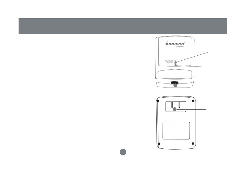
Front View:
1. Powerline LED – lights up in green when other
Homeplug devices are detected on the same
powerline
2. Link/ACT – blinks when data is sent through the
Homeplug connection
3. Ethernet port- connecting to the Ethernet of the
computer or the devices (router, wi-fi access
point, gaming box, etc.)
Back View:
4. Power connection – connecting the power outlet
Introduction
1
2
3
4
9
Page 9

Installation
There are several ways to network your computers using the HomePlug Bridge. Before we get started, please
NOTE:
Do not place HomePlug devices under direct sunlight or near high heat emitting devices;
Do not place HomePlug devices near water or wet surfaces to avoid electric hazards;
Do not place HomePlug devices on any moving or unstable surfaces;
It is recommended that you plug the HomePlug devices directly into the wall outlets, not to any power adapters,
surge protectors or any device that fi lters signals.
Hardware Installation
1. Remove the HomePlug Bridge, the CAT5 cable and the installation CD from the package.
2. Allocate a space for the adapter’s placement. Make sure you avoid the places mentioned above.
3. Plug one end of the CAT5 cable into the Ethernet port on the computer, and the other end into the
Ethernet port of the bridge.
4. Plug the HomePlug bridge on the wall outlet.
10
Page 10
Installation
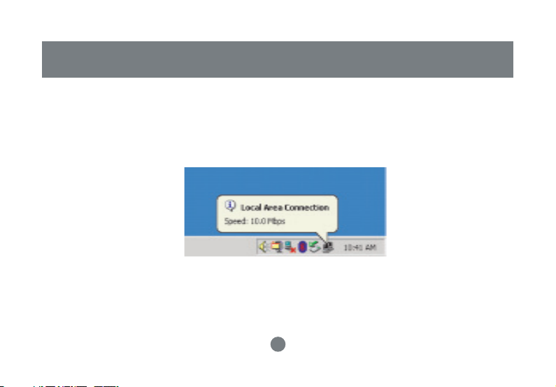
5. There are several ways to see whether the Homeplug bridge is functioning. One way is the observe
the LED, the Link/ACT LED should start blinking after you plug the bridge in the wall outlet. For most
of the Windows machines (as this Windows 2000 machine used to create this manual), you should
see a message being prompted on the tool bar: “Local Area Connection, Speed XX Mbps”. (Speed is
determined by the Ethernet port speed of the computer.)
11
Page 11
Installation
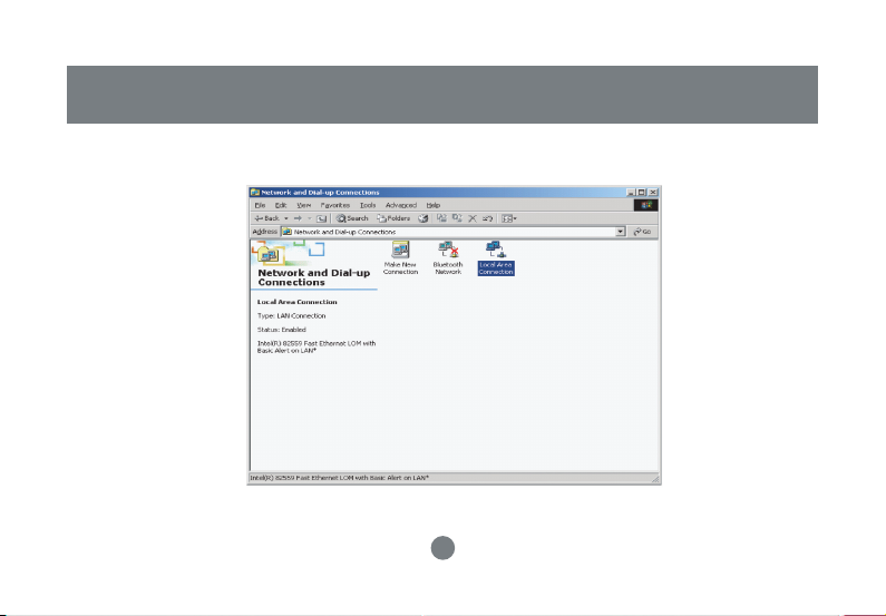
6. You can also go to “Control Panel”, select “Network and Dial up and Connections. ”Click the “Local Area
Connection” icon.
12
Page 12
Installation
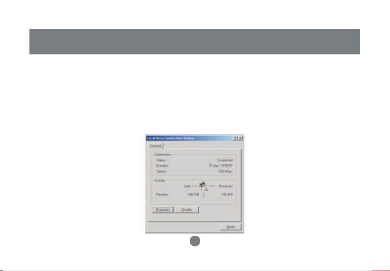
7. You can see the network connection is already established.
At this point, you can start communicating with the other computers or devices on the powerline. Please
refer to Network Confi guration section in how to set up networks for various purposes.
In order to add security and other utilities, you will need to install the utility software. Please refer to the
following section for details. Please notice that Homeplug bridge supports many other operating systems,
but the utility software is only designed for Windows based computers.
13
Page 13
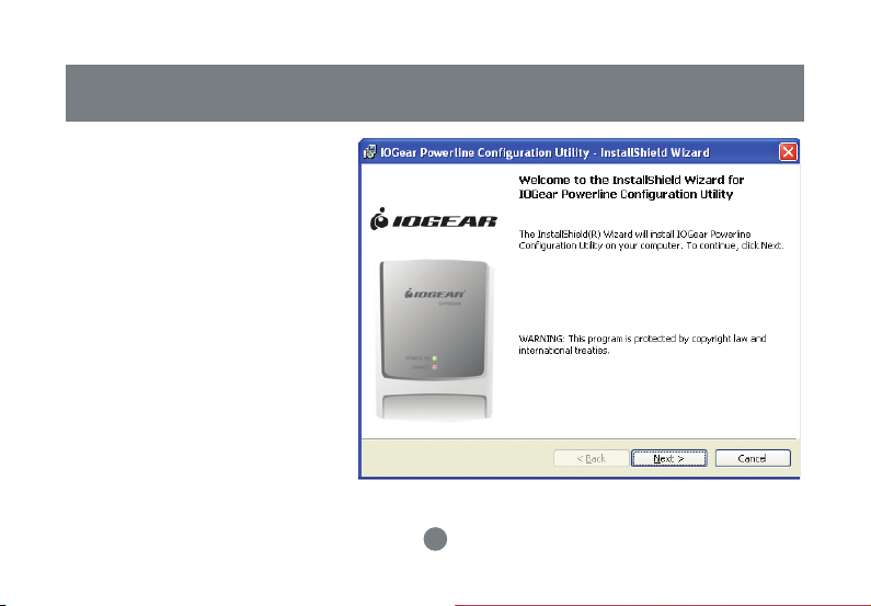
Installation of the utility software
1. Make sure that your HomePlug bridge
is NOT CONNECTED TO THE COMPUTER before you install the driver.
2. Insert the installation CD. If CD does
not automatically load, run (CD Drive
Letter):\setup.exe.
3. Click Next.
14
Page 14
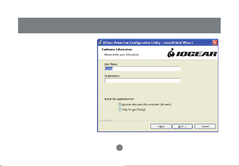
Enter a username and organization
4.
name, and continue installation.
(Username and Organization have
no importance in device operation.
This window might look slightly different on other platforms.)
Installation of the utility software
15
Page 15
Installation of the utility software
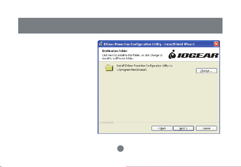
Click “Next” to continue.5.
16
Page 16
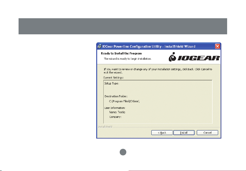
Click “Install” to start the Installation
6.
Wizard
Installation of the utility software
17
Page 17
Installation of the utility software
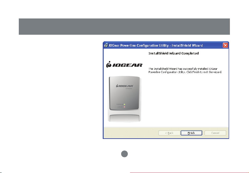
The following window will be
7.
prompted to indicate that the
installation is successful.
To uninstall the driver, simply go to your
Add/Remove programs control panel
and remove the IOGEAR Powerline
Confi guration Utilities. Then restort your
computer to complete the uninstall.
18
Page 18
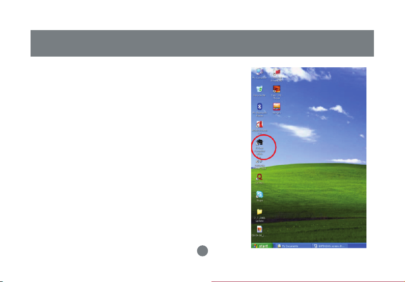
Double click the IOGear Powerline Utility icon to start
1.
the Powerline Confi guration Utility. The utility is used to
confi gure the Homeplug unit”
Powerline Confi guration Utility
19
Page 19
Powerline Confi guration Utility
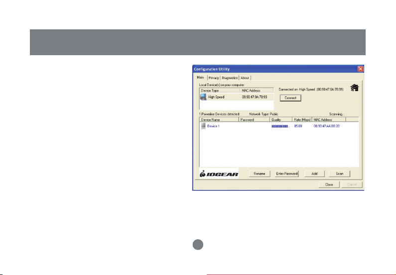
The Main tab shows the HomePlug units that
2.
are connected to the current computer and
other devices on the network. It will also tell
Mac Address of each device. It will refresh the
window, if you change devices, and also will
allow you to connect to different networks if
multiple units are connected to your computer.
The connection quality will show in the Quality
tab. You will have to do troubleshooting if see a
question mark at the Quality tab.
Note: If you do not see ANY unit in the device
status, and there is a device connected to your
computer, try to unplug all devices, and plug them
back in. Also make sure that the cable connecting
your computer to the HomePlug device is the right
type and working correctly. If all of this seems to be
correct, and you still receive nothing in the Device
window, try rebooting your computer. If the problem
still persists, please contact technical support
20
Page 20
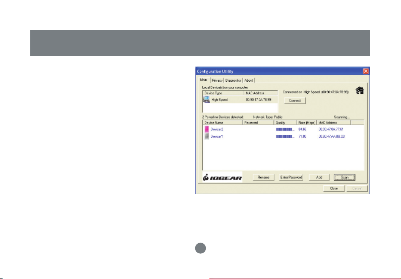
The Main tab shows all the other HomePlug
3.
units on your powerline network. It will
represent them by MAC Address, and will also
show the available bandwidth to each unit
(Units farther away from the current computer
might have a lower Data Rate, since the
distance is farther). If you add or subtract units
from your home network, you might want to
re-Scan, by clicking the “Scan” button. This
will rescan the network, and refresh with any
changes.
Note: Only units with the same Network Password
will be shown, please check that fi rst, to make
sure they all have the same network password
(Case sensitive).
Powerline Confi guration Utility
21
Page 21

Powerline Confi guration Utility
Note: If a Unit shows MAC Address of all 0’s, this
unit might not have a solid connection, or might
not connect at all. If this is the case please contact
technical support
Note: If there are units in your home, that you do not
see in this Network scan, try to unplug all devices,
and plug them back in (Only do this with the Units
that you do not view in the network screen, you
don’t have to do this with all units. If the problem
persists, try to move the unit closer to this current
unit (adjacent plugs on the same wall socket is most
preferable). If the problem still persists and that
unit is still not shown on the network, then the unit
might be defective please contact technical support.
Otherwise if you view the unit working, distance
might be the only issue.
22
Page 22
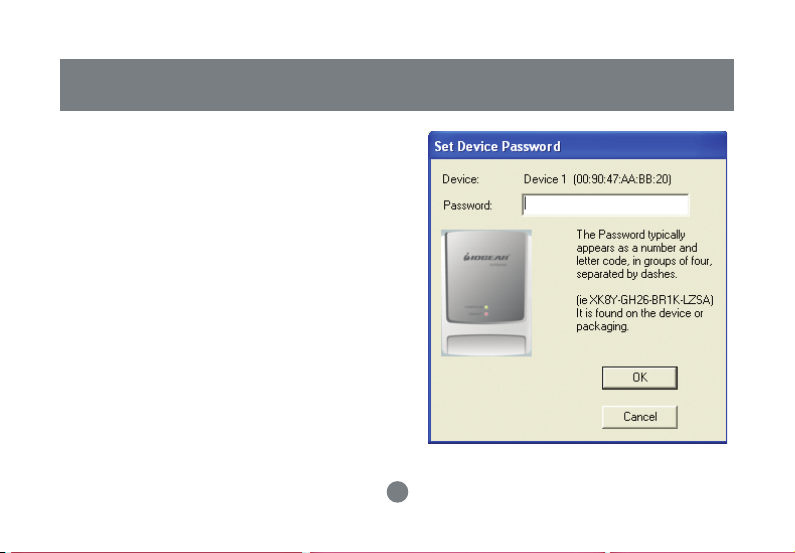
Press Enter Password button to put in the DEK
4.
(Device Encryption Key) found on the package
or device. Enter this key into the Password area.
Click OK. Add all the DEK keys for each unit in
your house.
Note: The DEK is unique for EACH HomePlug devices.
To use this you will need to input the DEK for each
unit.”
23
Powerline Confi guration Utility
Page 23
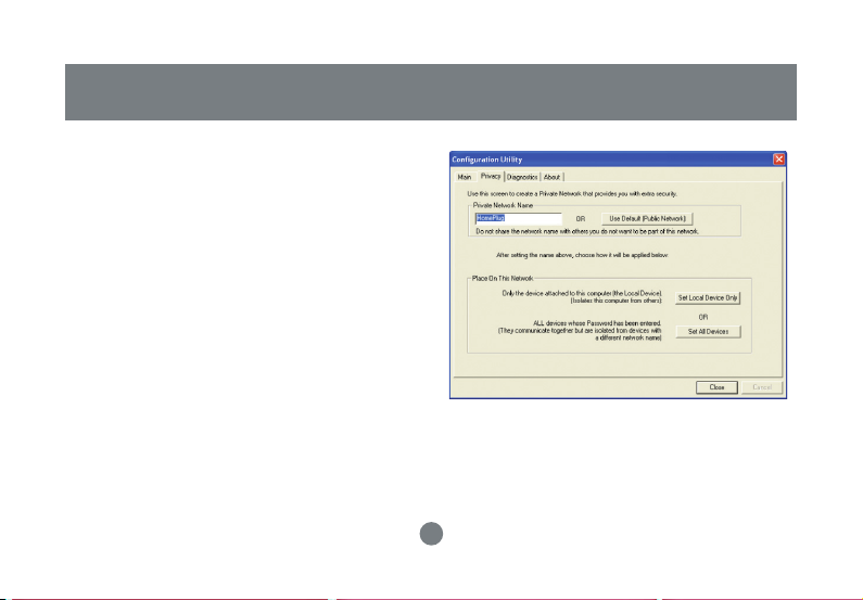
Powerline Confi guration Utility
After putting in the password, click on Set Local
5.
Devices Only to ensure all data that is sent
from this unit are encrypted using 56-bit data
encryption standard and isolated from the other
computer on the network.
Users may also use different network name for
each HomePlug device attached to a computer.
After successfully changing the network name,
click on Set All Devices to activate this feature.
It will isolate each HomePlug unit from each
other.
Note: Every unit on your home network MUST have
the same Network Name for connectivity to be
established throughout your home
24
Page 24

Powerline Confi guration Utility
The Diagnostics tab will allow users to see
6. This screen displays the version number
the devices that are currently available on
the powerline network
7.
of the utility. Click Close to complete the
confi guration.”
25
Page 25

Network Confi guration
Networking Terms
What is a node?
A node is any given device that resides or is connected onto an existing network. A computer with a network
card connected to a switch is a node. The same thing applies to a Mac connected to a hub.
What is a bridge?
A bridge is used when connecting one side of the network with another network. Previously, connecting
every computer together with the other network would mean having cables all over the place. Instead a
bridge was brought in to have 1 connection between the networks instead of 20. The bridge in the HomePlug terms functions like a concentration device that connects many computers onto the HomePlug network
using 1 HomePlug device.
How do I know if I require a node or a Bridge?
If you want to connect only one computer to the Power line network, you need a node. If you plan to connect a group of computers currently not HomePlug ready to the Power line network, you need a bridge. The
HomePlug USB adapter can only be used as a node. The HomePlug Ethernet Bridge can be used as either
a node or bridge. It is designed as a bridge in default; the only way to turn it off is to install the utility software
that comes with the unit. That will turn the bridge into a node.
26
Page 26

Network Confi guration
Can I use both in the same network?
Yes. It is perfectly right to have both nodes and bridges on a network as long the maximum is not exceeded.
It is also fi ne to have USB nodes on the same network with Ethernet nodes.
How do I decide whether I need a USB adapter or Ethernet bridge as a node?
It should be determined by the available connection on the computer that you plan to connect to the HomePlug
network. If the computer comes with a 10/100 Base-T network card, use the bridge; if the computer comes
with USB port, use the USB adapter. If the computer comes with both, you can decide which one to use based
upon your unique situation.
For Macintosh and other non-Windows based computers, the Ethernet Bridge is the only choice.
HomePlug Network Topologies
There are various ways to connect your computers via HomePlug. If all HomePlug units are used as nodes,
the topology is usually BUS. If bridges are used to connect two networks together, there maybe both BUS and
STAR. The following are several examples.
27
Page 27

Network Confi guration
a. Using the HomePlug Ethernet Bridge (Node Mode)
(Several HomePlug Bridges can be used)
28
Page 28

b. Using the HomePlug USB Adapter AND Ethernet Bridge (Node Mode)
29
Network Confi guration
Page 29

Network Confi guration
c. Using the HomePlug Ethernet bridge to make a sub network HomePlug ready to communicate with
the other HomePlug nodes.
Powerline
30
Page 30

Network Confi guration
d. Using the HomePlug Ethernet bridge to extend the WiFi network and eliminate dead spots.
31
Page 31

Network Confi guration
e. Using Homeplug bridge to share Broadband Internet access through the whole house.
32
Page 32

f. Using the HomePlug Ethernet bridge to play game remotely.
33
Network Confi guration
Page 33

Networking Basics
Prior to installing HomePlug, you may have had some ideas about using your new network. This section
will help you get started on those ideas or even give you some new ones. It will go through the process of
sharing fi les, printing from any computer on the network, or accessing the Internet on multiple computers
with one connection. Please note that this section is just an outline of a few networking basics and not
intended to be a comprehensive guide to networking.
Topic 1: Using Network Setup Wizard in Windows XP/2000
In the following section, you will learn how to set up a network at a home or business, using Microsoft
Windows XP/2000.
Go to My Computer>Control Panel>Network Connections.
Select “Set up a home or small offi ce network”.
34
Page 34

1. Click “Next” in the window(right) for the
Network Setup Wizard.
Networking Basics
35
Page 35

Networking Basics
2. Read and follow the instructions in
the following window and then click
“Next”.
36
Page 36

3. In the following window, select
among
the 3 options which best describe this
computer and then click “Next”. If your
computer connects to a broadband
router/gateway, select the second
Networking Basics
37
Page 37

Networking Basics
4. Fill in the information in the following
window as you desire and then click
“Next”.
38
Page 38

5. Enter the Workgroup name as
you wish and then click “Next”.
(Very important: All computers on
your network should have the same
Workgroup.
Networking Basics
39
Page 39

Networking Basics
6. Review the setting in the following
screen, and click “Next” to continue. If
you want to change any settings, you
need to click “Back” and start over again.
40
Page 40

7. Please wait while the Network Setup
Wizard applies the changes and confi gures
the computer.
Networking Basics
41
Page 41

Networking Basics
8. When the confi guration is done, the following
screen will come up. Select one of the 4 options
according to your needs. (In this example, the
last choice was selected.) Click “Next.”
42
Page 42

9. Then click “Finish” on this next window.
Networking Basics
43
Page 43

Networking Basics
10. The new setting will take effect after you restart the computer. Click “Yes” to restart the
computer.
Congratulations, you have completed confi guring this computer! After setting up networks on all your computers on
the network, you will be able to use your HomePlug network to share fi les, printers, and Internet connections.
44
Page 44

Topic 2: Checking IP addresses in Windows
XP/2000
Go to
Start>Programs>Accessories>
Command Prompt.
Networking Basics
45
Page 45

Networking Basics
1. Type “ipconfi g” at the prompt, then press Enter. You will see the IP address of this computer.
46
Page 46

Topic 3: Assigning a Static IP Address
(Note: If you use DHCP-capable gateway/router, you
don’t need to assign any static IP addresses because
the gateway/router will automatically assign IP addresses to the computers on the network.)
Go to Start>Settings>Control Panel>Network
Connections>Local Area Connection
Right click on Local Area Connection, then double
click on Properties, you will see a window similar
to this:
Select “Internet Protocol (TCP/IP)” and then click
on Properties.
Networking Basics
47
Page 47

Networking Basics
1. At the following window, select “Use the following
IP address:”, and fi ll in the desired IP address
and subnet mask (it is recommended to use the
default subnet mask as shown in the following
window. Subnet mask must be the same for all
the computers on the network.)
If you need to enter DNS address, you must
enter the address of the default gateway.
Click on “OK”.
48
Page 48

2.Click “Close” on the Local Area Connection
Properties window.
You have completed static IP address assignment.
Networking Basics
49
Page 49

Networking Basics
Topic 4. Sharing Disks/Folders
Once the network has been checked / confi gured, you can access other systems via “My Network Places”.
To allow other systems to access data on your disks / in your folders, you have to give permission to
share your disks and/or folders.
1. Select the disk (or the folder) to be shared (for example in “My Computer”) and right-click on the
icon of the disk to get the Context / popup-menu; select “Sharing and Security.”
It is recommended to share only folders instead of the disk drive to avoid any security related issues.
50
Page 50

Networking Basics
Once you have selected the
folder to be shared, rightclick to select “sharing and
security.”
51
Page 51

Networking Basics
2. In the following window, click to select “Share this
folder”. Then click on “Permission”.
52
Page 52

3. Please note that by default, all users defi ned on
your XP Professional system will have full
permissions. You can reduce the permissions
(for example to allow only Read-access) and/or
you could add a different group of users to have
access permission (but then you should delete
the group “Everyone” from this list).
In the following Permission settings, make sure
you are giving the right permissions and then
click OK to accept the settings.
Networking Basics
53
Page 53

Networking Basics
4. Click OK on the original Sharing and Security
window to conclude the process.
5. Once a disk or folder is shared, the icon will
show it via the “holding hand.”
54
Page 54

Topic 5. Share Printers
You may now share any installed printers connected to this computer with
other computers on your network.
1. Using the computer that has the
printer already connected to it, go
to: Start > Control Panel > Printers
and Faxes.
Click on the printer you want to share
with others on the network and select
“Share this printer”.
Networking Basics
55
Page 55

Networking Basics
2. In the following window, click on “Share this
Printer” and type in the share name you would like.
After this is done, click on “Apply” and then “OK”.
56
Page 56

Now when you go to “Printers
and Faxes” in the Control
Panel, you will see the supporting hand underneath the
printer, which means that the
printer is being shared in the
network.
Networking Basics
57
Page 57

Networking Basics
For a computer to access a Network
Printer, the device driver or software for
that printer must be installed and pointed
to the proper location of the printer. This
is done similarly to the way you installed
the printer on the computer it is connected to.
1. Go to a computer that is not
connected to the printer and select
“Start” from the Task Bar “Control Panel” then “Printers and other Hardware”.
58
Page 58

2. Click on “Add a printer”.
Networking Basics
59
Page 59

Networking Basics
3. Select the network printer
option and click Next.
60
Page 60

4. Find the printer you would
like to share and click Next.
Networking Basics
61
Page 61

Networking Basics
Decide if you would like to
choose this printer as a default
printer and click Next.
62
Page 62

You have now added the printer
to your computer, click Finish.
Now you may use the Network
Printer as if it was directly connected to the computer. Make
sure that the computer which is
directly connected to the printer
is on.
Networking Basics
63
Page 63

Sharing Internet Access
Topic 6. Sharing Internet Access
So how can the Internet connection be shared among other computers on the HomePlug network?
Since neither the HomePlug Bridge nor USB Adapter are capable of routing at this time, a router is necessary in order to share an Internet connection. Future versions of the HomePlug Bridge or USB Adapter
may feature built-in routing capabilities.
The following items are required for successfully sharing the Internet connection:
One (1) Router
One (1) HomePlug Bridge
One (1) DSL/Cable Modem
Active ISP Service for the DSL/Cable Modem
CAT5 Cables
Also all computers that share the Internet connection must be connected to a HomePlug to
USB Adapter or a HomePlug Bridge.
64
Page 64

Please follow these steps for setting up Internet Sharing:
65
Sharing Internet Access
Page 65

Sharing Internet Access
a. Make sure that the DSL/Cable modem is connected to the Router (using the WAN port on the router.)
b. Connect the HomePlug Bridge to the Router (using the Uplink port on the router.)
c. Check the link light on the HomePlug Bridge. It must light up green.
d. Make sure that the computers that need access to the Internet via the HomePlug network are each
connected to a HomePlug Adapter or a HomePlug Bridge and reside on the same power grid.
66
Page 66

Sharing Internet Access
Checking Router Settings:
Please make sure that the following settings on your router are set:
(The setup windows will depend on the router manufacturer’s software.)
A) The IP should be obtained automatically;
B) DHCP must be enabled;
C) Release DHCP and then Renew DHCP to reset the IP Addresses. It is recom-
mended that you verify that IP Addresses are obtained.
Once all the above steps have been completed, all HomePlug connected computers will be able to access the Internet.
67
Page 67

Frequently Asked Questions
Frequently Asked Questions/Troubleshooting
1. Will HomePlug work in my house or apartment?
If the house or apartment was built under U.S. building standards using copper wiring, then it will work.
2. What types of security problems will I be facing?
If your house is on the same power grid as your neighbor, then there is a potential for a
hacker to get in through your neighbor’s house. However, this is easily remedied by
activating the encryption key on the HomePlug device.
3. Will HomePlug work with Mac?
There is currently no software that supports Macs. However, the HomePlug Ethernet Bridge will work with
Mac when used as a bridge. Also, by installing Virtual PC software on a Mac, you will be able to install the
windows based software under Virtual PC and have this Mac communicate with other PCs on HomePlug
network.
What is the difference between bridge mode and node mode in the HomePlug Ethernet Bridge
4.
(GHPB42W6)?
Bridge mode operates without software installation and can work with any 10/100Base-T or 10Base-T Ethernet connections. By connecting the bridge to a router, switch, or Ethernet based device (XBOX, PlayStation,
Web Tablet, PocketPC, Computer, etc.), you will be able to make these devices bridge onto the HomePlug
68
Page 68

Frequently Asked Questions
network.
Node mode operates by connecting the Ethernet bridge (GHPB42W6) to one computer (ONLY) and
installing drivers onto the computer, allowing it to set the device into Node Mode. The advantage with
Node Mode operation is there is no limitation to the number of nodes that can operate on a HomePlug
network.
5. Will HomePlug operate on different Circuit Breakers?
Yes. Circuit breakers do not affect performance of HomePlug devices, however the signal will not pass
through the power transformers outside your house.
6. Can Neighbors get my HomePlug signal?
It is possible for your immediate (next door) neighbor to receive residual signal from your HomePlug
adapter. Unlikely, but possible. To prevent your neighbors from hacking your network, the best thing you
can do is type a different encryption password into your device when setting the encryption password.
Note: All devices must have the same password to be on one network. If devices do not have the
same encryption password, they will not be able to communicate with each other.
69
Page 69

Frequently Asked Questions
7. What OS does the HomePlug utility software fully support?
Windows 98SE, ME, XP, and 2000. Windows NT and Mac are only supported by the HomePlug Ethernet
Bridge (Without installing the HomePlug software with default operating mode as BRIDGE, not NODE)
8. What is the Range of HomePlug?
Approximately 990 feet (300 meters) in wall power lines.
9. How does 56bit-DES compare with Wireless 802.11b 128bit-WEP encryption?
56bit-DES is superior because of its DES type Encryption. Just because 802.11B uses 128bit-WEP with
more bits doesn’t mean the encryption is better. Also, the IOGEAR HomePlug devices use hardware
56bit-DES encryption. With hardware encryption the signal is almost impossible to crack. The hardware
encryption process does not affect bandwidth, and the encryption is enabled at all times.
70
Page 70

Technical Support
To help IOGEAR® customers obtain the highest level of performance from their HomePlug
devices, the IOGEAR® Service Support team is available to answer your technical questions. Do not hesitate to call if you are having trouble getting your device to work correctly.
IOGEAR® Service Support can be reached by phone from 9am to 5pm Pacifi c Standard
Time, Monday through Friday or at the following address:
Toll Free 866-9-IOGEAR (USA)
Phone: 949-453-8782
23 Hubble
Irvine, CA 92618
You may also reach us online at www.iogear.com/support 24 hours a day. Please be ready to
give a brief description of the problem, and what you were doing when the problem occurred,
before calling Service Support. The Service Support representative will be able to serve you
much quicker if you are prepared to answer the nine questions listed below.
71
Page 71

Technical Support
1) What is the purchase date and serial number of the product?
2) Were any messages displayed on the screen when the error occurred? If so, what
was the exact wording of the message?
3) What type of Computer are you using?
4) When does the problem occur?
5) Can the problem be reproduced? If so, what are the steps necessary to reproduce
the problem?
6) What version of the OS are you using?
7) Are you on a network? If so, what type of network is it?
8) What have you already tried to get the problem resolved?
72
Page 72

Specifi cations
73
Page 73

Limited Warranty
IN NO EVENT SHALL THE DIRECT VENDOR’S LIABILITY FOR DIRECT, INDIRECT, SPECIAL, INCIDENTAL OR CONSEQUENTIAL DAMAGES RESULTING FROM THE USE OF THE PRODUCT, DISK,
OR ITS DOCUMENTATION EXCEED THE PRICE PAID FOR THE PRODUCT.
The direct vendor makes no warranty or representation, expressed, implied, or statutory with respect to
the contents or use of this documentation, and especially disclaims its quality, performance, merchantability, or fi tness for any particular purpose.
The direct vendor also reserves the right to revise or update the device or documentation without
obligation to notify any individual or entity of such revisions, or updates. For further inquiries please
contact your direct vendor.
74
Page 74

Radio & TV Interference Statement
WARNING!!! This equipment generates, uses and can radiate radio frequency energy and, if not installed
and used in accordance with the instruction manual, may cause interference to radio communications. This
equipment has been tested and found to comply with the limits for a Class B computing device pursuant
to Subpart J of Part 15 of FCC Rules, which are designed to provide reasonable protection against such
interference when operated in a commercial environment. Operation of this equipment in a residential area
is likely to cause interference, in which case the user at his own expense will be required to take whatever
measures may be required to correct the interference.
75
Page 75

Contact info.
23 Hubble • Irvine, CA 92618 • (P) 949.453.8782 • (F) 949.453.8785 • www.iogear.com
 Loading...