

Page 1

User Manual
4-Port 4K Triple View DisplayPort KVMPTM
Switch with USB 3.0 Hub and Audio
www.iogear.com
Page 2

©2020 IOGEAR. All Rights Reserved. Part No. M1607. IOGEAR, the IOGEAR logo is trademarks of IOGEAR. Microsoft and
Windows are registered trademarks of Microsoft Corporation. IOGEAR makes no warranty of any kind with regards to the
information presented in this document. All information furnished here is for informational purposes only and is subject to change
without notice. IOGEAR. assumes no responsibility for any inaccuracies or errors that may appear in this document.
Page 3

Safety Instructions 4
Conventions 5
Introduction 6
Package Contents 6
Features 7
Requirements 8
Operating Systems 8
Overview 9
Hardware Setup 12
Six-Display (DCC Mode) 14
Basic Operation 16
Hotkey Operation 18
Advance Configuration 21
Mouse and Keyboard Emulation 24
Hotkey Settings Mode Summary Table 26
Keyboard Emulation 27
Sun Keyboard 28
Firmware Upgrade Utility 29
Specifications Chart 32
Troubleshooting 33
Compliance Information 33
Limited Warranty 33
Contact 33
FCC Information 34
3
Page 4

Safety Instructions
■ Read all of these instructions. Save them for future reference
■ This device is for indoor use only
■ Follow all warnings and instructions marked on the device
■ Do not place the device on any unstable surface (cart, stand, table, etc.). If the device
falls, serious damage will result
■ Do not use the device near water
■ Do not place the device near, or over, radiators or heat registers
■ The device cabinet is provided with slots and openings to allow for adequate
ventilation. To ensure reliable operation, and to protect against overheating, these
openings must never be blocked or covered
■ The device should never be placed on a soft surface (bed, sofa, rug, etc.) as this will
block its ventilation openings. Likewise, the device should not be placed in a built in
enclosure unless adequate ventilation has been provided
■ Never spill liquid of any kind on the device
■ Unplug the device from the wall outlet before cleaning. Do not use liquid or aerosol
cleaners. Use a damp cloth for cleaning
■ The device should be operated from the type of power source indicated on the marking
label. If you are not sure of the type of power available, consult your dealer or local
power company
■ The device is designed for IT power distribution systems with 230V phase-to-phase
voltage
■ To prevent damage to your installation, it is important that all devices are properly
grounded
■ The device is equipped with a 3-wire grounding type plug. This is a safety feature.
If you are unable to insert the plug into the outlet, contact your electrician to replace
your obsolete outlet. Do not attempt to defeat the purpose of the grounding-type plug.
Always follow your local/national wiring codes
■ Do not allow anything to rest on the power cord or cables. Route the power cord and
cables so that they cannot be stepped on or tripped over
■ If an extension cord is used with this device, make sure that the total Ampere ratings
of all products used on this cord does not exceed the extension cord Ampere rating.
Make sure that the total of all products plugged into the wall outlet does not exceed 15
Amperes.
■ To help protect your system from sudden, transient increases and decreases in
electrical power, use a surge suppressor, line conditioner, or un-interruptible power
supply (UPS)
■ Position system cables and power cables carefully; Be sure that nothing rests on any
cable
■ Never push objects of any kind into or through cabinet slots. They may touch
dangerous voltage points or short out parts resulting in a risk of re or electrical shock
■ Do not attempt to service the device yourself. Refer all servicing to qualied service
personnel
4
Page 5

■ If the following conditions occur, unplug the device from the wall outlet and bring it to
qualied service personnel for repair
o The power cord or plug has become damaged or frayed
o Liquid has been spilled into the device
o The device has been exposed to rain or water
o The device has been dropped, or the cabinet has been damaged
o The device exhibits a distinct change in performance, indicating a need for service
o The device does not operate normally when the operating instructions are followed
■ Only adjust those controls that are covered in the operating instructions. Improper
adjustment of other controls may result in damage that will require extensive work by a
qualied technician to repair
■ Do not connect the RJ-11 connector marked “UPGRADE” to a public telecommunication
network
Conventions
This manual uses the following conventions
Monospaced Indicates text that you should key in
[ ] Indicates keys you should press. For example, [Enter] means
to press the Enter key.
1. Numbered lists represent procedures with sequential steps
■ Bullet lists provide information, but do not involve
sequential steps
→ Indicates selecting the option (on a menu or dialog box, for
example), that comes next. For example, Start → Run means
to open the Start menu, then select Run
Indicates critical information
5
Page 6

Introduction
IOGEAR’s GCS1964 4-Port 4K Triple View DisplayPort KVMP Switch with USB 3.0 Hub
and Audio takes a giant leap forward in KVM switch functionality by combining KVM switch
with a Triple View KVM switch with DisplayPort video interface, 2-Port USB 3.0 hub and
2.1 channel audio for rich bass in surround sound. DisplayPort technology provides up
to Cinema 4K - 4096 x 2160 @60Hz and 4K UHD - 3840 x 2160 @60Hz resolution that
displays the most vivid high denition images available while delivering premium sound for
music, movies, and gaming.
GCS1964 allows users to access four DisplayPort computers from a single USB keyboard,
USB mouse, HDMI monitors. In addition to the front panel pushbutton and hotkeys,
IOGEAR’s GCS1964 offers the latest mouse port-switching functionality to change
ports. Power ON detection feature also ensures that if one computer is powered OFF,
the GCS1964 will automatically switch port to the next powered ON computer. Video
DynaSyncTM optimizes display resolution and enables fast switching between computer
sources, eliminating video delays.
With built-in USB 3.0 hub, each connected computer has SuperSpeed 5Gbps transfer rate
to all connected peripherals. GCS1964’s independent (asynchronous) switching feature
allows the KVM to focus on one computer while the USB peripheral focus on another.
This eliminates the need to purchase separate USB hub or stand-alone peripheral sharing
device – such as printer server, modem splitter, etc.
Featuring a revolutionary combination of 4K resolutions, the next generation USB 3.0 Hub,
and enhanced user-friendly operation, IOGEAR’s GCS1964 provides the latest innovations
in desktop KVM technology.
Package Contents
GCS1964
• 1 x 2-Port 4K Triple View DisplayPort KVMP Switch
• 6 x DisplayPort Cables
• 2 x USB 3.0 Cables
• 2 x Audio Cable Set
• 1 x Power Adapter
• 1 x Quick Start Guide
Please verify that all components are present and nothing was damaged in shipping. If you
encounter a problem, contact your dealer.
Read this manual thoroughly and follow the installation and operation procedure to prevent
any damage to the unit, and/or any of the devices connected to it
6
Page 7

Features
• 4-Port 4K Triple View DisplayPort KVMP Switch with USB 3.0 hub and 2.1 surround
sound audio
• One USB console controls four computers and two USB 3.0 peripherals
• Video DynaSync
• Computer selection via front panel pushbuttons, hotkeys, mouse
• Independent switching of KVM, USB, and Audio focus
• Superior 4K video quality – 4K UHD (3840 x 2160 @60Hz) and Cinema 4K (4096x2160
@60Hz)
• 2-Port USB 3.0 Hub with SuperSpeed 5Gbps transfer rate
• DisplayPort 1.2 compliant and HDCP compliant
• Supports N-key Rollover
• Supports 7.1 HD audio through DisplayPort
• Full bass response for high quality 2.1 channel surround sound systems
• Power On Detection – if a computer is powered OFF, GCS1964 automatically switches
to the next powered ON computer
• Hot pluggable – add or remove computers without turning GCS1964 power OFF
• Mouse emulation or bypass feature supports most mouse drivers and multifunction mice
• Multi-platform support
• Multilingual keyboard mapping supports English, French, German, and Japanese
keyboards
®
• Mac
keyboard support and emulation
• Auto Scan Mode feature to monitor all computers
• Firmware upgradeable
TM1
support optimizes switching between computers, eliminating delays
4
(NKRO) - permits collision-free keying
5
6
2
, or RS-232 command
3
Note:
TM
1. DynaSync
support optimizes switching between sources and eliminates boot-up
issue
2. Mouse port switching supported by mouse emulation mode using a USB 3-button
mouse wheel
3. Slide the DCC switch to the s (Client) position to allow the GCS1964 to receive
RS-232 commands via a DB9 to RJ-45 cable. Please refer to the GCS1964 RS-232
Commands Manual. DB9 to RJ-45 cable is not included.
4. N-key Rollover supports up to 15 simultaneous keystrokes
5. HD audio through DisplayPort cannot be switched independently
6. PC keyboard combinations emulate Mac
®
keyboards.
7
Page 8

Requirements
Console
• 3 x HDMI monitors
• Standard 2 or 3-button wired USB mouse
• Standard 104-key wired USB keyboard
• Microphones and speakers (optional)
Computers
• 3 x DisplayPort ports
• Type-A USB port
• Audio ports (optional)
Cables
We recommend using the included IOGEAR DisplayPort KVM cable sets, designed
specically to work with the GCS1964. Extra cable sets G2L9302U may be purchased
separately.
Note:
The quality of the display is affected by the quality and length of the cables.
If DisplayPort 1.1 cables are being used instead, please make sure that the DisplayPort
EQ setting on the monitor is set to auto or DP 1.1
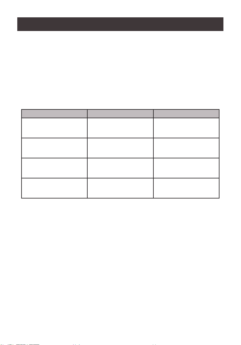
Operating Systems
OS Version
Windows
Linux
Mac
7 / 8 / 10 and higher
RedHat 9.0, Fedora and higher, RHEL AS 4, RHEL 5
SUSE 10 / 11.1 and higher; Open SUSE 10.2; SLES 10 SP1
Debian 3.1 / 4.0
Ubuntu 7.04 / 7.10 and higher
OS 10.1 / 10.2 / 10.3 / 10.4 / 10.5 / 10.7 / 10.8 and higher
8
Page 9
4-PORT TRIPLE VIEW DISPLAYPORT KVMP
GCS1964
1
2
5
4
9 88 8 8
10
6 7
11
3
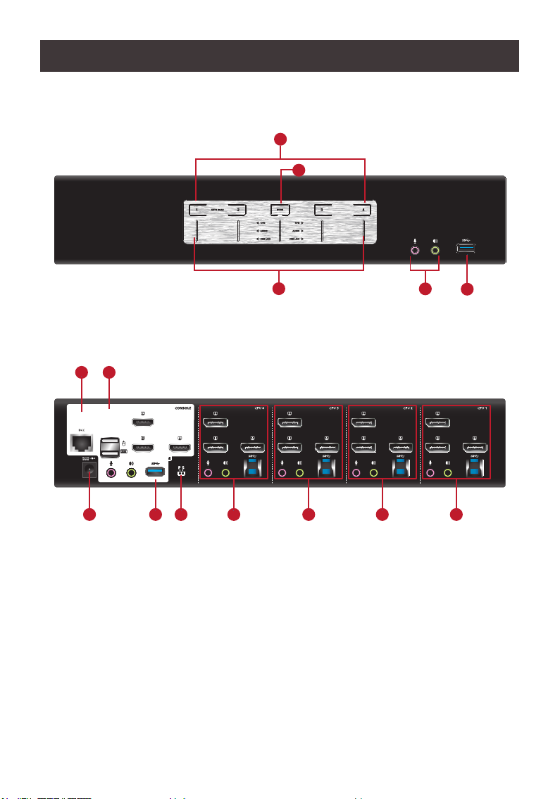
Overview
GCS1964 Front View
GCS1964 Back View
9
Page 10

No. Component Description
1 Port Selection
Pushbuttons
For manual port selection (see Manual Switching)
• Press a port selection pushbutton for longer than two seconds to bring the KVM, USB
hub, and audio focus to the computer connected to its corresponding port
• Press a port selection pushbutton twice to bring the audio focus to the computer
connected to its corresponding port
• Press a port selection pushbutton for less than two second to bring only the KVM focus
to the computer connected to its corresponding port
• Press pushbutton 1 and 2 simultaneously for two seconds
2 Port LEDs The Port LEDs are built into the Port Selection Pushbuttons. The upper LEDs are KVM Port
3 Mode Selection
Pushbutton
4 Console Audio
Ports
5 USB 3.0 Hub USB peripherals (printers, scanners, etc.) can be connected into this port. The built-in USB 3.0
6 DCC Port (Daisy
Chain Control)
LEDs, the lower LEDs are the USB LEDs:
KVM
• Online LED lights DIM GREEN to indicate that the computer attached to the
corresponding port is connected
• Selected LED lights BRIGHT GREEN to indicate that the computer attached to the
corresponding port is the one that has the KVM FOCUS (Selected)
• LED ashes to indicate that the computer attached to its corresponding port is being
accessed under Auto Scan Mode
USB
• Selected LED lights GREEN to indicate that the computer plugged to its corresponding
port has the access to the USB Peripherals
• This pushbutton allows you to cycle through the four focus modes – complete, KVM,
audio and USB
• Press and hold Mode Selection Pushbutton before powering on to enter Firmware
Upgrade Mode
The cables from the main microphone and speakers are to be connected into these audio
ports
Microphone and speakers connected into these audio ports have priority over those
connected in the rear side panel of the GCS1964
ports feature 5 Gbps data transfer rates for compatible USB peripherals.
This RJ-45 port is used to
• Connect two units together when setting up DCC mode for Six-Display mode. See Six-
Display (DCC Mode) for instructions
• Connect an RJ-45 to DB9 cable for RS-232 accesss (cable not included)
7
Console Ports
8 KVM Ports The KVM cables from the computers are connected into these ports.
9 Power Jack The power adapter cable is connected into this jack.
10 USB 3.0 Hub USB peripherals (printers, scanners, etc.) can be connected into this port. The built-in USB 3.0
11 DCC Switch This switch is used to
The cables from the HDMI monitors, USB keyboard, USB mouse, speakers, and
microphone are connected into these ports.
Each connector is marked with an appropriate icon to indicate its use
Each KVM port section is comprised of a microphone jack, speaker jack, USB type B socket
and three DisplayPort connectors
ports feature 5 Gbps data transfer rates for compatible USB peripherals.
• Specify the Host (p) and Client (s) when setting up two units in Six-Display DCC mode.
See Six-Display (DCC Mode) for instructions
• Receive RS-232 commands by sliding switch to s position.
10
Page 11
Port LED Behavior
The LED of currently focused connectors (KVM, Audio, USB Link) will be fully-lit
The LED(s) of KVM connectors not currently focused but connected will be half-lit
The LED(s) of Audio and USB link connectors not currently focused will be dimmed
Mode Selection Pushbutton and Mode LED Behavior
Pressing the Mode Selection Pushbutton different number of times will light up different
Mode LED, which allows for the follow-up action shown in the table. For more information
on the follow-up actions, please refer to Manual Switching
Button Press Mode LED that lights up Follow-up Action
Once KVM, Audio, USB Press any of the Port
pushbutton to select focus
for all connectors
Twice KVM Press any of the Port
pushbutton to select focus
for the KVM connector
Three times Audio Press any of the Port
pushbutton to select focus
for Audio connectors
Four Times USB Press any of the Port
pushbutton to select focus
for USB link
Note: When Mode KVM LED blinks, that means the KVM was set to “s” (Client)
11
Page 12

Hardware Setup
Hardware Installation
Please read Safety Instructions before proceeding with installation
Please make sure that all devices including the GCS1964, HDMI monitors, and computers
are powered OFF
1. Please make sure that GCS1964 DCC Switch is on p (Host).
2. Connect the USB keyboard and the USB mouse to the GCS1964 Console ports
located on the rear side panel
3. Connect the HDMI monitors to the GCS1964 Console ports located on the rear side
panel. For multiple monitor setups, see Six-Display (DCC) section
4. Turn monitor(s) power to ON
5. Connect the main analog microphone and speakers into the GCS1964 microphone
and speaker jacks located on the front side panel (optional). The microphone and
speakers connected into this front port have priority over those connected on the rear
port.
6. Connect the secondary analog microphone and speakers into the GCS1964 Console
microphone and speaker jacks located on the rear panel (optional)
7. Using the included DisplayPort 1.2 cables, connect the connector into any available
DisplayPort “A” port in the KVM Port section of the GCS1964. Then, connect the
included USB 3.0 cable, microphone and/or speaker cables into their corresponding
sockets.
8. At the other end of the cable sets from step 7, connect the DisplayPort 1.2 cable, USB
3.0 cable, and microphone/speaker cables into their respective ports on the computer
9. Using three separate DisplayPort 1.2 cables, connect the DisplayPort connectors into
the DisplayPort “B” and “C” ports in the same KVM port section of the switch.
10. At the other end of the DisplayPort 1.2 cables from step 9, connect the monitor cables
into their respective ports on the computer.
11. Repeat steps 7 – 10 for each triple display PC system being installed
12. Connect the USB peripherals into the front or the rest of the USB peripheral ports
(optional)
13. Connect the provided power adapter to an AC power source. Then, connect the power
adapter cable into the GCS1964 power jack.
14. Turn all connected computers power to ON
Note: Verify that all the connectors are on the same KVM Port sockets (all in Port 1, all in
Port 2, etc.) and that each socket is marked with an appropriate icon to indicate itself
By default, the GCS1964 switches to the rst computer that is powered ON
We recommend that the total video cable length from the computer to the console monitor
not to exceed 3 meters (10 feet).
Please make sure that only high quality video cables used in order to achieve Cinema 4K
(4096 x 2160 @60Hz) or 4K UHD (3840 x 2160 @60Hz).
12
Page 13

GCS1964
2 3
9
6 1
4-PORT TRIPLE VIEW DISPLAYPORT KVMP
GCS1964
111113
11
7
8
10
5
12
13
Page 14

Six-Display (DCC Mode)
To expand your installation from a Two-Display to a Six-Display, please use DCC Mode to
connect the two GCS1964 units together and use four 4K displays in unison
To set up DCC mode, power OFF all devices and refer to the installation diagram on the
next page (the numbers in the diagram correspond to the steps below), and follow below
steps:
1. Please make sure your computer has 6 x DisplayPort ports to achieve Six-Display
setup.
2. Please also make sure you have two GCS1964 ready for Six-Display installation. For
each installation, one KVMP switch will act as Host while the other as Client
3. On the rear side by console section of the Client GCS1964, set the DCC switch to “s”
4. On the rear side by console section of the Host GCS1964, set the DCC switch to “p”
5. Connect all computers to the Host GCS1964 as described in Hardware Setup.
6. On the Client GCS1964, using three DisplayPort cables, connect the DisplayPort
connectors into the DisplayPort ports “A”, “B” and “C” in the same KVM port section of
the switch.
7. At the other end of the three DisplayPort cables, connect the monitor cables into their
respective ports on the computer for each triple screen PC system installed
8. Repeat steps 6 and 7 for all computers
9. Connect the console monitors into the DisplayPort console ports located on the Host’s
and the Client’s rear panel.
10. Use an RJ-45 cable to connect the DCC port of the Host to the DCC port of the Client
11. Connect the power cord for the Host and Client to wall sockets then turn both
installations on. After both units are up, turn on the computer or video source devices.
Note:
1. P stands for Primary, S stands for Secondary
2. In DCC Mode, the Client’s front panel pushbuttons are disabled, and it will take com
mands directly from the Host
3. Setting the DCC switch to Client will disable all front panel pushbuttons on that switch.
14
Page 15

GCS1964
4K
4K4K
3 2 1
3 2 1
4K4K4K
15
Page 16

Basic Operation
Basic Operation
There are three convenient methods to access the computer:
a. Manual – involves pressing the port selection pushbuttons located on the GCS1964’s
front panel
b. Hotkey – involves entering combinations from the keyboard (see Hotkey Operation
section for details)
c. Mouse – involves pressing the mouse wheel button (clicking it twice) to switch
between ports (see Mouse Emulation and Mouse Port Switching section for more
details)
Manual Switching
For Manual Port Selection:
■ To bring complete focus of Audio, KVM/Video and USB
○ Press the Mode pushbutton once (the Mode pushbutton’s three icons light up) then
press the port selection pushbutton that corresponds to the computer attached to
the corresponding port. All three port icons lights up.
■ To bring only the KVM/Video focus to a computer
○ Press the Mode pushbutton twice (the Mode pushbutton’s KVM icon lights up) then
press the port selection pushbutton that corresponds to that computer. The port’s
KVM icon (the port number) lights up.
■ To bring only the Audio focus to a computer
○ Press the Mode pushbutton three times (the Mode pushbutton’s audio icon lights
up) then press the port selection pushbutton that corresponds to that computer.
The port’s audio icon lights up.
■ To bring only the USB focus to a computer
○ Press the Mode pushbutton four times (the Mode pushbutton’s USB icon lights up)
then press the port selection pushbutton that corresponds to that computer. The
port’s USB icon lights up.
■ To start Auto Scan Mode, press and hold port selection pushbutton 1 and 2
simultaneously for two seconds. To stop Auto Scan Mode, press and release either port
selection. The KVM focus goes to the computer attached to the corresponding port of the
pushbutton you pressed.
Note:
If a port is not selected within 5 seconds of pushing the Mode pushbutton, the Mode
pushbutton will power off
Hot Plugging
The GCS1964 support USB hot plugging – components can be removed and added back
into the installation by unplugging their cables from the USB hub ports, without the need to
shut the unit down.
16
Page 17

Powering OFF and Restarting
If it becomes necessary to Power OFF the GCS1964, before switching it back ON, you must
follow below steps:
1. Shut down or Power OFF all computers that are attached to the GCS1964
2. Unplug the GCS1964 power adapter cable
3. Wait for 10 (ten) seconds, then plug the GCS1964 power adapter cable back into the unit
4. After the GCS1964 turns ON, power ON all the attached computers
Port ID Numbering
Each KVM port section on the GCS1964 is assigned a port number
1, 2, 3, or 4 for the GCS1964
The port numbers are marked on the rear panel of the GCS1964
The Port ID of a computer is derived from the KVM port number it is connected to. For example,
a computer connected to KVM port 2 has a Port ID of 2.
The Port ID is used to specify which computer gets the KVM, USB peripherals, and audio focus
with the Hotkey port selection method (see Hotkey Operation for details)
Alternative Manual Port Selection Settings
When Hotkey Setting Mode has been activated, pressing [S] will invoke the alternative front
panel pushbutton manual port selection functions as follows:
• Press a port selection pushbutton once to bring only the KVM, audio and USB focus to the
computer attached to its corresponding port
• Press a port selection pushbutton twice to bring the audio focus to the computer attached to
its corresponding port
• Press and hold a port selection pushbutton for more than 2 seconds to bring only the KVM
focus to the computer attached to its corresponding port
• Press and hold port selection pushbuttons 1 and 2 for more than 2 seconds to start Auto
Scan Mode (see Auto Scan Mode for details)
17
Page 18

Hotkey Operation
IOGEAR’s GCS1964 provides an extensive, easy-to-use, hotkey function for convenience
in controlling and conguring KVM installation from the keyboard. Hotkeys provide
asynchronous (independent) switching of the KVM, USB hub, and audio focus. Therefore,
users can give one computer the KVM focus, another the USB hub focus, while a third has
the audio focus.
Port Switching
All port switching begins by clicking [Scroll Lock] twice. The tables below describe the
actions that each combination performs
Note: If using the [Scroll Lock] key conicts with other programs running on the computer,
the [Ctrl] key can be used, instead. See Alternate Port Switching Key for details.
Cycling Through the Ports
Hotkey Function
[Scroll Lock][Scroll Lock][Enter]
[Scroll Lock][Scroll Lock][K][Enter] Brings only the KVM to the next higher port.
[Scroll Lock][Scroll Lock][U][Enter] Brings only the USB to the next higher port*
[Scroll Lock][Scroll Lock][S][Enter] Brings only the Audio to the next higher port.
Brings the KVM, USB hub, and Audio focus to
the next higher port (1 to 2; 2 to 3; 3 to 4; 4 to 1).
Note: The KVM, USB hub, and Audio focus all go
to this port even if they were on different ports to
begin with.
The USB and audio focus remain where they are.
The KVM and audio focus remain where they are.
The KVM and USB hub remain where they are.
18
Page 19

Going Directly to a Port
Hotkey Function
[Scroll Lock][Scroll Lock][n][Enter]
Brings the KVM, USB hub, and Audio focus to
computer attached to [n] port.
[n] stands for the computer’s Port ID number.
Replace [n] with the appropriate Port ID when
entering hotkey combinations.
Note: The KVM, USB, and Audio focus all go
to this port even if they were on different ports to
begin with.
[Scroll Lock][Scroll Lock][n][K][Enter] Brings only the KVM to the computer on [n] port.
The USB hub and audio focus remain where
they are.
[Scroll Lock][Scroll Lock][n][U][Enter] Brings only the USB focus to the computer on [n]
port.
The KVM and audio focus remain where they are.
[Scroll Lock][Scroll Lock][n][S][Enter] Brings only the Audio to the computer on [n] port.
The KVM and USB hub focus remain where they
are.
[Scroll Lock][Scroll Lock][n][K][U]
[Enter]
Brings the KVM and USB focus to the computer
on [n] port.
The audio focus remain where it is.
[Scroll Lock][Scroll Lock][n][K][S]
[Enter]
Brings the KVM and Audio focus to the computer
on [n] port.
The USB hub focus remain where it is.
[Scroll Lock][Scroll Lock][n][U][S]
[Enter]
Brings the USB hub and Audio focus to the
computer on [n] port.
The KVM focus remain where it is.
19
Page 20

Auto Scan Mode
GCS 1964’s Auto Scan feature allows you to monitor computer activities without switching
from port to port manually. This feature automatically cycles the KVM focus through the
computer ports at regular intervals. See table below for details
When Auto Scan is in effect, only Auto Scan Mode compliant keystrokes and mouse clicks
work. Ordinary keyboard and mouse functions are suspended. Click [Esc] or Space Bar to
exit Auto Scan Mode to regain normal control of the console.
Although video focus switches from port to port, keyboard, mouse and USB focus do not
switch. They remain on the port when Auto Scan began.
Hotkey Function
[Scroll Lock][Scroll Lock][A][Enter] Invokes Auto Scan
The KVM focus cycles from port to port at 5
seconds (default) intervals.
[Scroll Lock][Scroll Lock][A][n][Enter] The KVM focus cycles from port to port at [n]
second intervals.
Note
1. The [n] stands for the number of seconds that the GCS1964 should dwell on a port
before moving on to the next port. Replace [n] with a number between 1 and 99 when
entering this hotkey combination.
2. While Auto Scan Mode is in effect, ordinary keyboard and mouse functions are
suspended – only Auto Scan Mode compliant keystrokes and mouse clicks can be
input. You must exit Auto Scan Mode in order to regain normal control of the console
3. Although the video focus switches from port to port, the keyboard, mouse, and USB
focus do not switch. They stay at the port they were on when Auto Scanning started
4. To exit Auto Scan Mode, press [Esc] or Spacebar
20
Page 21

Advance Conguration
Hotkey Setting Mode
Hotkey Setting Mode is used to set up your GCS1964 switch configuration. All operations
begin with invoking Hotkey Setting Mode (HSM).
To invoke HSM (Default)
1. Press and hold down [Num Lock] (use [Clear] on Mac)
2. Press and release [-] minus key
3. Release [Num Lock] key (use [Clear] on Mac)
4. To exit HSM manually, press [Esc] or Spacebar
Note: The [-] minus key must be released within one half second, otherwise Hotkey
invocation is cancelled
When HSM is active, [Caps Lock] and [Scroll Lock] LEDs will flash in succession to indi-
cate that HSM is in effect. They will stop flashing and revert to normal status when you exit
HSM
Only Hotkey compliant keystrokes and mouse clicks (described on Hotkey Settings Mode
Summary table) function. Ordinary keyboard and mouse functions are suspended while on
HSM
At the conclusion of some hotkey operations, you can automatically exit hotkey mode. With
some operations, you must exit manually by pressing [Esc] or Spacebar
Alternative HSM Invocation Keys
In some instances, the default hotkey settings conict with programs running on your
computer and in some instances the default hotkeys either do not exist on your keyboard
(Mac keyboards do not have [Scroll Lock]), or are inconvenient to use, Hotkey Setting
Mode allows you to select alternate congurations for the KVM’s hotkeys. An alternate set of
HSM invocation keys is provided in case the default set conicts with programs running on
the computers.
On Alternate HSM, the HSM invocation keys become the [Ctrl] key (instead of Num Lock)
and [F12] (instead of [-] minus key)
To switch to the Alternate HSM invocation set:
1. Invoke Default HSM above
2. Press and release [H]
Note: This procedure is a toggle between the two methods. To revert back to the original
HSM invocation keys, invoke HSM, then press and release [H] key again.
21
Page 22

Alternative Port Switching Keys
The port switching activation keys can be changed from clicking [Scroll Lock] key twice
([Scroll Lock][Scroll Lock]) to clicking [Ctrl] key twice ([Ctrl][Ctrl])
To change the port switching activation keys:
1. Invoke HSM
2. Press and release [T] key
Note: This procedure is a toggle between the two methods. To revert back to the default
[Scroll Lock][Scroll Lock] method, invoke HSM, then press and release [T] key again
List Switch Settings
To see a listing of the current switch settings:
1. Open a text editor or word processor and place the cursor in the page window
2. Invoke HSM
3. Press and release [F4] to display the settings
USB Reset
If the USB loses focus and needs to be reset:
1. Invoke HSM
2. Press and release [F5]
Keyboard Language
To change the keyboard language:
1. Invoke HSM
2. Press [F6] [nn] [Enter]
Note: [nn] is a two-digit number that represents the keyboard language code
US English: 33
French: 08
German: 09
Hotkey Beeper
The Beeper can be hotkey toggled ON and OFF. To toggle the Beeper:
1. Invoke HSM
2. Press and release [B]
The Beeper toggles ON or OFF
Port Switching Keys
To disable the Port Switching Keys ([Scroll Lock][Scroll Lock]) or ([Ctrl][Ctrl]):
1. Invoke HSM
2. Press [X] [Enter]
Note: This procedure is a toggle. To enable the Port Switching keys, repeat Step 1 and 2
22
Page 23

Firmware Upgrade Mode
To set the GCS1964 to Firmware Upgrade Mode:
1. Invoke HSM
2. Key in [u][p][g][r][a][d][e]
3. Press [Enter]
The front panel LEDs will flash to indicate the Upgrade has started
Note: To exit Firmware Upgrade Mode, you must power OFF the GCS1964
Restore Default Settings
To reset the GCS1964 to its default hotkey settings:
1. Invoke HSM
2. Press [R][Enter]
All hotkey settings return to the factory default settings
Alternative Manual Port Selection
To toggle between the default and the alternative front panel pushbutton manual port
selection settings:
1. Invoke HSM
2. Press [S]
This procedure is a toggle. Repeat to revert to the original setting. See Alternative
Manual Port Selection for more information
Power on Detection
With Power on Detection, if the focus computer is powered OFF, the GCS1964 will automatically switch to the next powered ON computer. Power on Detection can be enabled
or disabled. The default setting is enabled. To disable Power on Detection:
1. Invoke HSM
2. Press and release [E]
This procedure is a toggle. Repeat to revert to the original setting
SPC Mode
To set the keyboard/mouse to use SPC mode so that it can work under special operating
systems as a standard (104 key) keyboard/mouse:
1. Invoke HSM
2. Press [F1]
23
Page 24

Mouse and Keyboard Emulation
Mouse Emulation
To toggle between mouse emulation enabled and disabled:
1. Invoke HSM
2. Press [M]
3. This procedure is a toggle. Repeat to revert to the original setting.
Mouse Port Switching
Mouse Port Switching allows you to use the mouse wheel button (clicking it twice) to switch
between ports. Mouse Emulation (above) must be enabled in order for Mouse Port Switching
to work. To toggle between mouse port switching enabled and disabled:
1. Invoke HSM
2. Press [W]
This procedure is a toggle. Repeat Step 1 and 2 to disable Mouse Port Switching
Note: This feature is only supported by 3-key USB scroll wheel mice. The default setting is
OFF. This feature is only supported when mouse emulation is also enabled.
Keyboard Emulation
Console keyboard port emulation/bypass feature supports most gaming/multimedia
keyboards. The default setting is enabled. To disable:
1. Invoke HSM
2. Press [N]
This procedure is a toggle. Repeat Step 1 and 2 to enable Keyboard Emulation
Note: When keyboard emulation is disabled, the [M], [W], [F2], [F3], [F4], [F5], [F6], and
[F10] are also disabled
24
Page 25

Keyboard Operating Platform
IOGEAR’s GCS1964 default port conguration is for PC compatible keyboard operating
platform. If the console uses a PC compatible keyboard and a Mac or Sun computer is
attached to GCS1964, the port’s Keyboard Operating Platform conguration can be changed
so that the PC compatible keyboard emulates Mac keyboard, by
1. Bring the KVM focus to the port you want to set
2. Invoke HSM
3. Press and release the appropriate Function keys listed on table below
Key Function
[F1] To set the keyboard/mouse in SPC mode so it works under special
operating system as a standard (104 key) keyboard/mouse
[F2] Enables Mac keyboard emulation, see Mac Keyboard
Emulation.
[F10] Disables keyboard emulation. Key presses are passed straight
through. You’re your console uses a Mac keyboard to access a
Mac attached to a port, for example. Automatically detects and
sets the keyboard operating platform
4. You will automatically exit HSM once this procedure is completed
N-Key Rollover Keyboard Supporting Function
Keyboard must have NKRO support in order this function to work on the GCS1964. Also,
please make sure to turn off Keyboard emulation off rst in order to turn NKRO function on.
To enable/disable N-key rollover keyboard supporting function:
1. Invoke HSM
2. Press [K]
25
Page 26

Hotkey Settings Mode Summary Table
Key Function
[B] Enables/Disables the beeper/buzzer
[E] Enables/Disables Power ON Detection feature
[H] Toggles between the default combination ([Num Lock][-]) and
[K] Enables/Disables N-key rollover keyboard supporting function
[M] Enables/Disables mouse emulation
[N] Enables/Disables keyboard emulation
[R][Enter] Resets the hotkey settings to their default status*
[S] Toggles between the default and alternate manual port selection
[T] Toggles between the default combination ([Scroll Lock][Scroll
[u][p][g][r][a][d][e]
[Enter]
[W] Enables/Disables mouse port-switching
[X][Enter] Enables/Disables the port switching keys*
[Wheel][Wheel] When the mouse switching function is activated, double click the
[F1] Allows the keyboard/mouse to work under special operating
[F2] Enables Mac keyboard emulation
[F3] Enables Sun keyboard emulation
[F4] Lists current switch settings via Paste function of a text editor
[F5] Performs a reset on all USB devices
[F6][nn][Enter] Sets the keyboard language
[F10] Automatically detects and sets the keyboard operating platform
[Esc] or [Spacebar] Quits and exits the setting mode
alternate combination ([Ctrl][F12])
pushbutton settings
Lock]) and alternate combination ([Ctrl][Ctrl])
Invokes Firmware Upgrade Mode
mouse wheel to switch to the next port
systems as a standard (104 key) keyboard/mouse
Note: nn is a two-digit number that represents one of the following
keyboard language code:
US English:33
French:08
German:09
Japanese:15
*Hotkey cannot be set as a front panel pushbutton combo key
26
Page 27

Keyboard Emulation
Mac Keyboard Emulation
The PC compatible (101/104 key) keyboard can emulate the functions of Mac keyboard. The
emulation mapping are listed in table below
PC Keyboard Mac Keyboard
[Shift] Shift
[Ctrl] Ctrl
[Ctrl][1]
[Ctrl][2]
[Ctrl][3]
[Ctrl][4]
[Alt] Alt
[Print Screen] F13
[Scroll Lock] F14
=
[Enter] Return
[Backspace] Delete
[Insert] Help
[Ctrl] F15
Note: When using key combinations, press and release the rst key [Ctrl], then press and
release the activation key.
27
Page 28

Sun Keyboard
The PC compatible (101/104 key) keyboard can emulate the functions of the Sun keyboard
when the Control key [Ctrl] is used in conjunction with other keys. The corresponding
functions are shown in the table below
PC Keyboard Sun Keyboard
[Ctrl] [T] Stop
[Ctrl] [F2] Again
[Ctrl] [F2] Props
[Ctrl][F4] Undo
[Ctrl][F5] Front
[Ctrl][F6] Copy
[Ctrl][F7] Open
[Ctrl][F8] Paste
[Ctrl][F9] Find
[Ctrl][F10] Cut
[Ctrl] [F1]
[Ctrl] [F2] -
[Ctrl] [F3] +
[Ctrl] [F4]
[Ctrl] [H] Help
Compose
Note: When using key combinations, press and release the first key [Ctrl], then press and
release the activation key.
28
Page 29

Firmware Upgrade Utility
Firmware Upgrade Conguration
GCS1964 Windows based Firmware Upgrade Utility (FWUpgrade.exe) provides a smooth-
automated process for rmware upgrade.
The Utility comes as part of a Firmware Upgrade Package that is specic for each device.
New rmware upgrade packages are posted on our IOGEAR.COM website, as new rmware
revisions become available. Please check the website regularly to nd latest packages and
information relating to rmware revisions and upgrades.
Before Starting Firmware Upgrade
In order to better perform a rmware upgrade, using a computer that is not connected to the
GCS1964 setup is recommended. To set GCS1964 to Firmware Upgrade Mode:
1. From a computer that is not part of the KVM installation, go to www.iogear.com/product/
GCS1964 to get a list of available Firmware Upgrade Packages
2. Choose the Firmware Upgrade Package (usually the most recent one), and download the
le to a computer that is not part of the KVM installation
3. If you have a DCC mode installation, remove the RJ-45 cable connected to the DCC port
that connects the two units, and set both DCC switches to “p” (Host)
4. Disconnect the GCS1964 from the KVM installation and power the switch OFF.
5. Connect one of the USB DisplayPort KVM cable set’s Type A USB connectors to a USB
Type A port on the computer that is not part of your KVM installation
6. At the other end of the cable set, connect the USB Type B connector to the Type B USB
port in Port 1 KVM section on the GCS1964.
Note: The USB DisplayPort KVM cable set’s USB Type B connector can be connected
to any USB Type KVM Port Section, but the Port Selection pushbutton in Step 6 below
must be Port 1
7. Press and hold Mode selection pushbutton.
8. While holding Mode selection pushbutton, connect the power adapter to the GCS1964 to
enter Firmware Upgrade Mode.
9. The front panel LEDs will ash together, indicating Firmware Upgrade Mode is in effect.
Starting Firmware Upgrade
1. Run the downloaded Firmware Upgrade Package le – either by double clicking the le
icon, or using a command line to enter the full path.
29
Page 30

2. The Firmware Upgrade Utility Welcome
screen appears.
3. Read the License Agreement and click
“I Agree” button and click “Next”.
4. The Firmware Upgrade Utility main
screen appears. The Utility inspects
your installation. All the devices capable
of being upgraded by the package are
listed in the Device List panel.
5. As you select a device from the list,
the device’s description appears in the
Device Description panel. After you
have made your device selection(s),
Click “Next” to perform the upgrade
30
Page 31

6. If you enabled Check Firmware Version,
the Utility compares the device’s
rmware level with that of the upgrade
les. If the device’s version is higher
than the upgrade version, a dialog
box below will give you the option to
Continue or Cancel.
7. If you did not enable Check Firmware
Version, the Utility installs the upgrade
les without checking whether they are
of higher level, or not.
8. As the Firmware Upgrade proceeds,
a vstatus message will appear in
the Status Messages panel, and the
progress toward completion is shown on
the Progress bar
9. After the upgrade has completed, a
screen appears to inform you that the
procedure was successful. Click Finish
to close the Firmware Upgrade Utility.
10. After a successful completion, the
GCS1964 will exit the Firmware
Upgrade Mode and resets itself.
11. If the GCS1964 is under DCC mode
installation, then please be sure to
reconnect the cable connected to the
DCC port and set the DCC switch on the
Client KVM switch back to “s” (Client)
(see Six-Display DCC Mode)
Firmware Upgrade Fail
If the Upgrade Succeeded screen does not appear, this means that the upgrade failed to
complete successfully. If this occurs, please follow below steps:
1. Power off the GCS1964 by removing the power adapter
2. Invoke Firmware Upgrade Mode by holding down the Mode Selection pushbutton
on the front panel (see Mode Selection Pushbutton) and power on the GCS1964.
The orange LEDs ash together.
3. Repeat the upgrade procedure from the beginning (see Before Starting Firmware
Upgrade).
31
Page 32

Specications Chart
Function GCS1964
Connections Computer 4
Console 1
Port Selection Pushbuttons, Hotkey, Mouse*, RS-232
Connectors Console
Ports
KVM
Ports
USB Hub 1 x USB 3.0 Type A (Blue; Front)
Serial 1 x RJ-45 Female
Power 1 x DC Jack
Switches Selected 5 x Pushbutton
LED On Line / Selected 4 (Green)
USB Link 4 (Green)
Emulation Keyboard / Mouse USB
Video
Scan Interval 1-99 second (5 second Default)
Power Consumption DC 12V
Environment Operating Temp. 0 - 50°C
Storage Temp. -20 – 60°C
Humidity 0 – 80% RH, Non-c ondensing
Housing Metal
Keyboard 1 x USB Type A (Black)
Video 3 x DisplayPort (Black)
Mouse 1 x USB Type A (Black)
Speakers
Microphone
Keyboard / Mouse 4 x USB 3.1 Gen1 Type B (Blue)
Video 12 x DisplayPort (Black)
Speakers 4 x 3.5mm Mini Stereo Jack (Green)
Microphones 4 x 3.5mm Mini Stereo Jack (Pink)
1 x 3.5 mm Mini Stereo Jack (Green; Front)
1 x 3.5 mm Mini Stereo Jack (Green; Rear)
1 x 3.5 mm Mini Stereo Jack (Pink; Front)
1 x 3.5 mm Mini Stereo Jack (Pink; Rear)
1 x USB 3.0 Type A (Blue; Rear)
4096 x 2160 @60Hz (Cinema 4K)
3840 x 2160 @60Hz (4K UHD)
Commands
*Mouse emulation mode and mouse port switching mode must be turned on for mouse port switching with
3-button wheel USB mouse
32
Page 33

Troubleshooting
Operation problems occur due to variety of causes. The rst step in solving them is to make
sure that all cables are securely attached and plugged in completely in their sockets.
In addition, updating the GCS1964 rmware may solve problems that have been discovered
and resolved since the prior version was released. If your product is not running the latest
rmware version, we strongly recommend that you upgrade. See The Firmware Upgrade
Utility for upgrade details.
Compliance Information
Limited Warranty
Warranty Information
This product carries a 3 Year Limited Warranty. For the terms and conditions of this
warranty, please go to https://www.iogear.com/support/warranty
Register online at https://www.iogear.com/registration
Important Product Information
Product Model
Serial Number
Contact
WE’RE HERE TO HELP YOU! NEED ASSISTANCE SETTING UP
THIS PRODUCT?
Make sure you:
1. Visit www.iogear.com for more product information
2. Visit www.iogear.com/support for live help and product support
IOGEAR
www.iogear.com
iogear.custhelp.com
support@iogear.com
33
Page 34

FCC Information
FEDERAL COMMUNICATIONS COMMISSION INTERFERENCE STATEMENT
This equipment has been tested and found to comply with the limits for a Class B digital
service, pursuant to Part 15 of the FCC rules. These limits are designed to provide
reasonable protection against harmful interference in a residential installation. Any changes
or modications made to this equipment may void the user’s authority to operate this
equipment. This equipment generates, uses, and can radiate radio frequency energy. If
not installed and used in accordance with the instructions, may cause harmful interference
to radio communications. However, there is no guarantee that interference will not occur
in a particular installation. If this equipment does cause harmful interference to radio or
television reception, which can be determined by turning the equipment off and on, the user
is encouraged to try to correct the interference by one or more of the following measures:
• Reorient or relocate the receiving antenna.
• Increase the separation between the equipment and receiver.
• Connect the equipment into an outlet on a circuit different from that to which the receiver
is connected.
• Consult the dealer or an experienced radio/TV technician for help.
This device complies with Part 15 of the FCC Rules. Operation is subject to the following
two conditions:
1. this device may not cause harmful interference, and
2. this device must accept any interference received, including interference that may
cause undesired operation.
FCC Caution: Any changes or modications not expressly approved by the party
responsible for compliance could void the user’s authority to operate this equipment.
CE Compliance
This device has been tested and found to comply with the following European Union
directives: Electromagnetic Capability (2004/108/EC), Low Voltage (2006/95/EC) and
R&TTED (1999/5/EC).
!
WARNING: This product can expose you to chemicals including styrene which is known
to the State of California to cause cancer and birth defects or other reproductive harm. For
more information, go to www.P65Warnings.ca.gov
34
Page 35

Page 36

 Loading...