

Page 1

Quick Start Guide
18.5” Widescreen Short Depth VGA LCD
KVM Console
GCL1900W
PART NO. Q1602
www.iogear.com
Page 2

Package Contents
1 x 18.5” Widescreen Short Depth VGA LCD KVM Console
1 x USB VGA KVM Cable
1 x Firmware Upgrade Cable
1 x Grounding Wire
1 x Power Cord
1 x Standard Rack Mounting Kit
1 x Quick Start Guide
System Requirements
Computers:
• VGA, SVGA, or MultiSync video graphics card
with an HDB-15 port
• Type-A USB port
• Audio port (optional)
External Console:
• VGA monitor
• Standard 2 or 3-button wired USB mouse
• Standard 104-key wired USB keyboard
• Speaker (optional)
1
Page 3
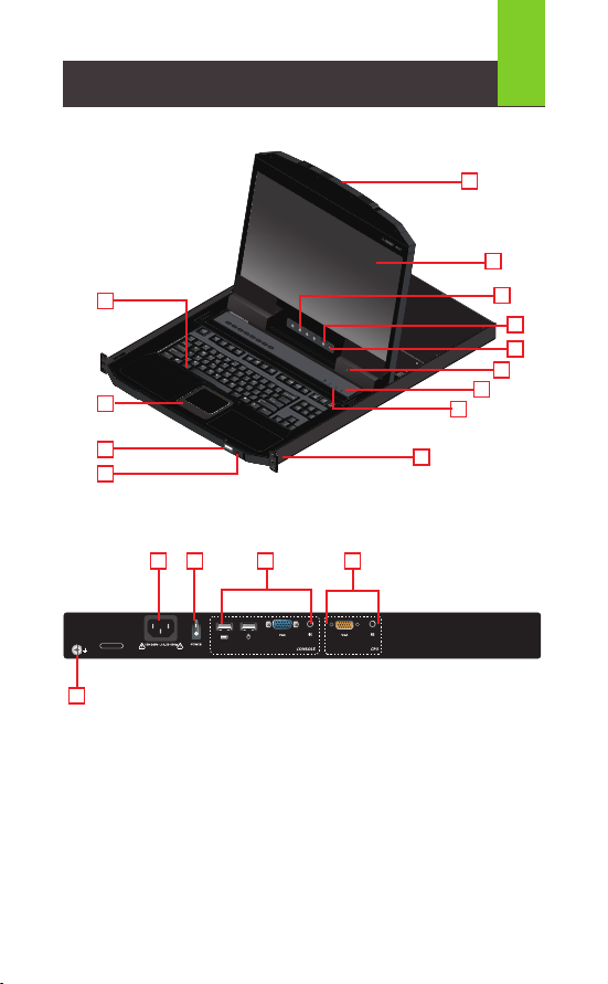
Overview
Front View
1
13
1
12
1
11
1
10
Rear View
2
1
1
1
2
1
3
1
4
1
5
1
6
1
7
1
8
1
9
1151
14
GCL1900W
1
18
1
16
1. Upper Handle with Release Bar
2. LCD Module
3. LCD Controls
4. LCD ON/OFF Button
5. Firmware Upgrade Switch
6. Firmware Upgrade Port
7. Reset Switch
8. Lock LEDs
9. Rack Mounting tabs
1
17
10. Power LED
11. USB Port
12. Touchpad
13. Keyboard Module
14. Power Socket
15. Power Switch
16. External Console Section
17. KVM Port Section to CPU
18. Grounding Terminal
Page 4

Hardware Installation
Standard Rack Mounting
1. Please use the included standard rack mounting kit to mount the
GCL1900W in a rack with a depth of 16.5"-28.3"
Note:
a. We highly recommend two people to mount the module: one to hold it in place
and the other person to screw the module in
b. The included standard rack mounting kit does not include screws or cage nuts.
Please contact your sales representative for additional screws or cage nuts
2. Attach the left and right mounting brackets to the back of the rack,
installing four screws into the tabs to secure the brackets in place
3
3. While one person inserts the GCL1900W into place by sliding its left
and right side bars into the mounting brackets (on the rack), have the
second person install four screws in the front tabs to secure the
module to the front of the rack
Note:
Please allow at least 2" on each side for proper ventilation and at least 5" at the
back for the power cord and cable clearance
Page 5

Hardware Installation
Connecting Cables
1. Connect the VGA and audio connectors of the included KVM cable into
the KVM ports located in the CPU section on the rear of the GCL1900W
Note:
The GCL1900W supports speakers only. It does not support microphones. Connect
the KVM cable’s speaker jack (green) to the GCL1900W’s audio port
2. Connect the USB, VGA and audio connectors of the KVM cable into
their respective ports of a computer
3. If an external console is needed, connect the keyboard, mouse, VGA
monitor and speakers (microphone not supported) into their respective
ports on the Console Section of the GCL1900W
4. Connect the GCL1900W to an AC power source using the included
power cord
5.Turn on the GCL1900W power
Power Socket
Power Switch
441
5
GCL1900W
1
1
Grounding
Terminal
1
3
USB VGA
4
1
2
Page 6

Operation
5
Opening the Console
1. Pull on the Release bar on the Upper Handle
2. Slide the console module out until it clicks in place then raise the
LCD Module lid
Closing the Console
3. Lower the LCD Module until it lies flat and slide the full console in
1 2 3
Operating Precautions
The maximum load bearing capacity of the keyboard module is 66 lb.
Failure to heed below information can result in damage to the keyboard
module
Right!
Rest your hands and arms lightly on the
keyboard module as you work.
Wrong!
• DO NOT lean your body weight on the
keyboard module
• DO NOT place heavy objects on the
keyboard module.
Page 7

Hotkey Commands
Combination Action
[Ctrl][Alt][Shift][P][C][Enter] To select normal mode (PC, etc)
[Ctrl][Alt][Shift][M][A][C][Enter] To select Mac
[Ctrl][Alt][Shift][S][U][N][Enter] To select SUN
[Ctrl][Alt][Shift][L][Enter] Activates the Firmware Upgrade Mode
Note: this Hotkey sequence only works
when the Firmware Upgrade Recovery
Switch is in NORMAL position
[Ctrl][Alt][Shift][L][Enter] Enable Local (LCD) console
Disable 2nd console or external
console video
[Ctrl][Alt][Shift][R][Enter] Enable 2nd console or external video
Disable Local (LCD) console
[Ctrl][Alt][Shift][L][R][Enter] or
[Ctrl][Alt][Shift][R][L][Enter]
[Ctrl][Alt][Shift][U][M][Enter] Confi gures the front USB port to mouse
[Ctrl][Alt][Shift][U][P][Enter] Confi gures the front USB Port to
[Ctrl][Alt][Shift][F4][Enter] Print the switch’s current settings via a
[Ctrl][Alt][Shift][F11][F][Enter] Set the KVM port to USB full speed
[Ctrl][Alt][Shift][F11][L][Enter] Set the KVM port to USB low sped
Enable both consoles (default)
mode (Mouse functionality is immediate
upon switching to USB mouse mode)
USB mouse mode [U][M] is the default
peripheral mode
text editor or word processor
6
Page 8

Limited Warranty
This product carries a 3 Year Limited Warranty. For the terms and
conditions of this warranty, please go to
https://www.iogear.com/support/warranty
Register online at https://www.iogear.com/register
Important Product Information
Product Model
Serial Number
Page 9

Contact
WE’RE HERE TO HELP YOU!
NEED ASSISTANCE SETTING UP THIS PRODUCT?
Make sure you:
1. Visit www.iogear.com for more product information
2. Visit www.iogear.com/support for live help and product support
IOGEAR
https://iogear.custhelp.com
support@iogear.com
www.iogear.com
Page 10

EMC Information
Federal Communications Commission Statement (FCC)
Statement:
This equipment has been tested and found to comply with the
limits for a Class A digital service, pursuant to Part 15 of the FCC
rules. These limits are designed to provide reasonable protection
against harmful interference in a residential installation. Any
changes or modifications made to this equipment may void the
user’s authority to operate this equipment. This equipment
generates, uses, and can radiate radio frequency energy. If not
installed and used in accordance with the instructions, may cause
harmful interference to radio communications. However, there is
no guarantee that interference will not occur in a particular
installation. If this equipment does cause harmful interference to
radio or television reception, which can be determined by turning
the equipment off and on, the user is encouraged to try to correct
the interference by one or more of the following measures:
• Reorient or relocate the receiving antenna.
• Increase the separation between the equipment and receiver.
• Connect the equipment into an outlet on a circuit different from
that to which the receiver is connected.
• Consult the dealer or an experienced radio/TV technician for
help.
CE Statement
This device has been tested and found to comply with the
following European Union directives: Electromagnetic Capability
(2004/108/EC), Low Voltage (2006/95/EC) and
R&TTED (1999/5/EC).
© 2020 IOGEAR
 Loading...