

IOGear GCS1716 Installation Manual

1
GCS1716
PART NO. M1074
Installation
Installation Guide
16-Port USB PS/2 Combo KVM Switch

2
3
©2008 IOGEAR. All Rights Reserved. PKG-M1074
IOGEAR, the IOGEAR logo, MiniView®, VSE are trademarks or registered trademarks of IOGEAR, Inc. Microsoft and
Windows are registered trademarks of Microsoft Corporation. IBM is a registered trademark of International Business
Machines, Inc. Macintosh, G3/G4 and iMac are registered trademarks of Apple Computer, Inc. IOGEAR makes no warranty
of any kind with regards to the information presented in this document. All information furnished here is for informational
purposes only and is subject to change without notice. IOGEAR, Inc. assumes no responsibility for any inaccuracies or
errors that may appear in this document.

3
Table of Contents
Package Contents 4
Requirements 5
Product Overview 7
Features 8
Hardware overview 10
Hardware Setup 15
Basic Operation 28
OSD Operation 32
Keyboard Port Operation 51
Keybard Emulation 63
Firmware Upgrade Utility 67
Limited Warrany 74
Federal Communications Commission
(FCC) Statement
75
Contact 76
Technical Support 77
Specications 79
Troubleshooting 85
Appendix 86

4
5
Package Contents
1 x GCS1716 16-Port KVM Switch with Standard Rack Mounting Kit –
2 x Custom KVM cable sets (1 USB and 1 PS/2) –
1 x Console cable –
1 x Cascading cable –
1 x Firmware Upgrade cable* –
1 x Grounding wire –
1 x Foot Pad set (4 pads) –
1 x Power Adapter –
1 x User Manual** –
1 x Quick Start Guide –
1 x Warranty Registration Form –
Check to make sure that all the components are present and that nothing got damaged in shipping. If you encounter a
problem, contact your dealer. Read this manual thoroughly and follow the installation and operation procedures carefully to
prevent any damage to the unit, and/or any of the devices connected to it.
* Upgraded rmware may have been developed since you last purchased the product. Please visit our website to check and
download the latest rmware version.
** Features may have been added to the GCS1716 since this manual was printed. Please visit our website to download the
most up-to-date version of the manual.
5
Requirements
Console
The following hardware components are required for the KVM console:
A VGA, SVGA, or multisync monitor capable of displaying the highest resolution provided by any –
computer in the installation.
A keyboard and mouse (USB or PS/2) –
Computers
The following hardware components are required for each computer:
A VGA, SVGA, or multisync video graphics card with an HDB-15 port. –
PS/2 mouse and keyboard ports (6-pin mini-DIN), at least one USB port. –
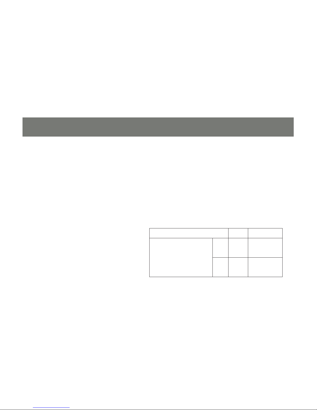
Function Length Part Number
KVM switch to computer
(or to another switch if
cascading) connection
PS/2 6 ft
10 ft
20 ft
G2L-5202P
G2L-5203P
G2L-5206P
USB 6 ft
10 ft
16 ft
G2L-5202U
G2L-5203U
G2L-5205U
Cables
Sub-standard cables might damage the
connected devices or degrade overall
performance. For optimum signal integrity
and to simplify the layout, use the high quality
IOGEAR custom cable sets described below.

6
7
Operating Systems
Supported operating systems are shown in the table, below:
OS Version
Windows 2000 or higher, XP, Vista
Linux RedHat 7.1 or higher, Fedora Core 2, Fedora Core 3,
Fedora Core 4
SuSE 8.2, 9.3, 10
Mandriva (Mandrake) 9.0

7
Product Overview
The GCS1716 KVM switch allows access and control up to 256 computers from a single console (keyboard,
mouse, and monitor). As many as 16 additional switches can be cascaded bringing the total number of
connected computers to 256 computers that can be controlled from a single keyboard-monitor-mouse
console. Additionally, the GCS1716 features high density SPHD 15-pin instead of the usual 25-pin connectors
thus allowing for a compact design and installation in a 1U system rack.
The GCS1716 includes one USB port located on the front panel for easy access and sharing of any USB
peripherals. Setup is fast and easy; plugging cables into their appropriate ports is all that is needed. The
switch supports both USB and PS/2 connections for the console and computers. The GCS1716 intercepts
keyboard input directly, thus eliminating the need for any software conguration. Switching between computers
can be easily accomplished either by manually pressing the front panel push button port LEDs, entering
hotkey combinations from the keyboard, or via a menu driven multilingual on-screen display (OSD) system. A
convenient auto-scan feature permits automatic scanning and monitoring of activities on all connected. Lastly,
the GCS1716 offers benets such as: a) managing multiple computers from a single console, b) eliminating
the expense of having to purchase a separate keyboard, monitor, and mouse for each computer, c) space
and energy costs savings, and d) helping create a greener environment by reducing amount of waste.

8
9
Features
A single console controls up to 256 computers•
Cascade to 2 levels – connect up to 16 switches•
Front panel USB port allows each computer to access USB peripherals*•
Dual Interface – supports computers with PS/2 or USB keyboards and mice•
Multiplatform support – Windows 2000/XP/Vista, Linux, Mac, and Sun•
Supports multimedia USB keyboards for PC, Mac and Sun•
Auto PS/2 and USB interface detection•
USB or PS/2 keyboard and mouse emulation – computers boot even when the console focus is •
elsewhere
Superior video quality – up to 2048 x 1536; DDC2B•
Display Emulation Technology – stores the console monitor’s EDID (Extended Display Identication Data) •
to optimize display resolution
Convenient computer switching via front panel pushbuttons, hotkeys, or multilingual on-screen display •
(OSD) menu
Two level password security - only authorized users view and control computers; up to four users and •

9
an administrator with a separate prole for each
Auto Scan feature for monitoring user-selected computers•
Broadcast mode – operations simultaneously performed on all selected computers•
Hot pluggable – add or remove computers without having to power down the switch•
Buzzer on/off via hotkey and OSD•
Firmware upgradeable•
No software installation required•
Designed for desktop or rack mount (19” system rack, 1U)•
* The USB peripheral function only works with USB cable set connections. It will not work with PS/2 cable
set connections.
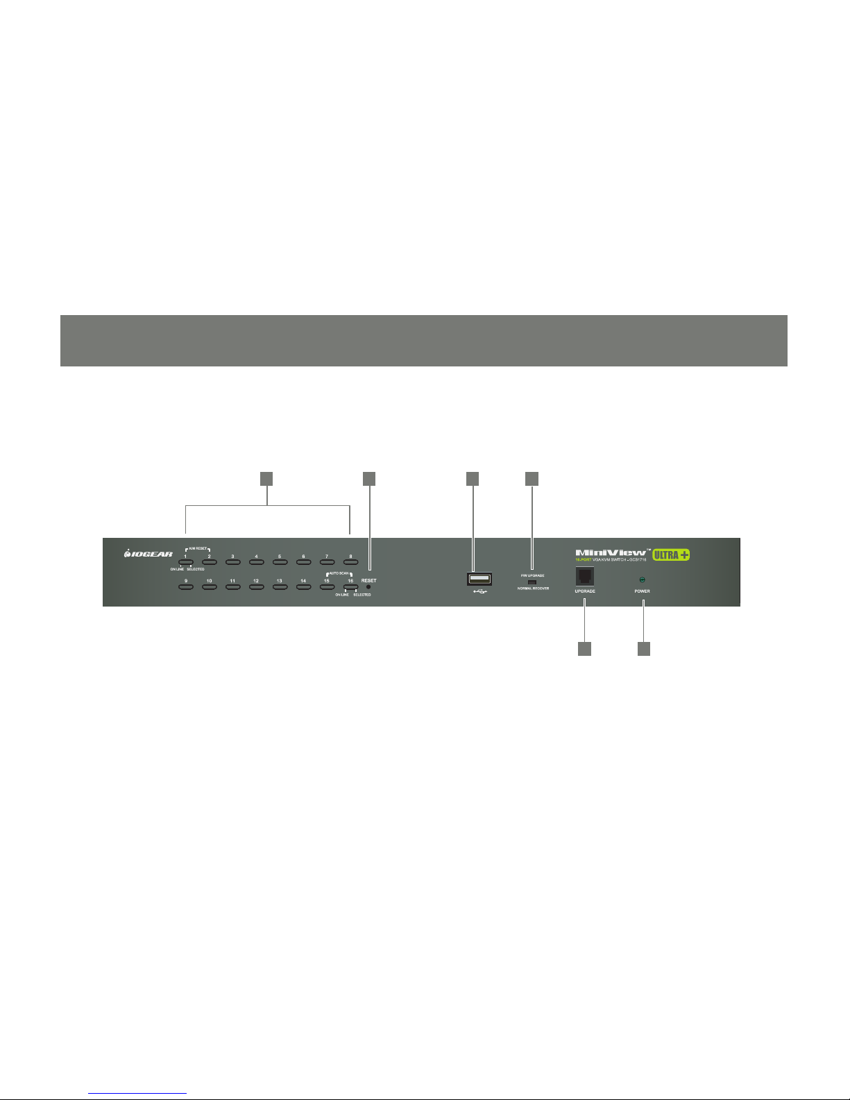
1 2 3 4
5 6
Front view
10
11
Hardware Overview

11
No. Component Description
1 Port LED’s These port selection push buttons each contain 2 LEDs.
An orange LED indicates that a computer is connected to the corresponding •
port.
A green LED indicates that the computer connected to the corresponding •
port has focus.
Simultaneously pressing port LEDs 1 & 2 resets the console keyboard and •
mouse.
Simultaneously pressing port LEDs 15 & 16 on the GCS1716 starts Auto •
Scan mode. See F7: SCAN
2 Reset
Button
Pressing this button performs a system reset. When the system is reset, the
GCS1716 beeps, and then the KVM port LEDs ash in succession until the reset
is completed. After the reset is complete, you can login again.
Note: This button is semi-recessed and must be pushed with a small object,
such as the end of a paper clip or a thin ballpoint pen.
3 USB Port USB peripherals (ash drive, CD-ROM, etc.) plug into this port.

12
13
No. Component Description
4 Firmware
Upgrade
Recovery
Switch
During normal operation and while performing a rmware upgrade, this switch
should be in the NORMAL position. If a rmware upgrade operation does not
complete successfully,
this switch is used to perform a rmware upgrade recovery
5 Firmware
Upgrade
Port
The rmware upgrade cable that transfers the rmware upgrade data from the
administrator’s computer to the GCS1716, plugs into this RJ-11 connector.
6 Power LED Lights green to indicate that the unit is receiving power.
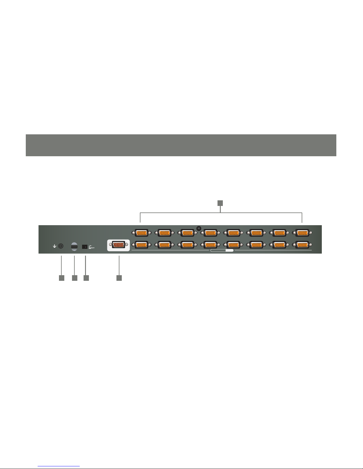
Back view
1234 5 678
11121314 15 161718
PS/2-USB
CPU
CONSOLE
213 4 5
13

No Components Description
1 KVM Ports The cables that link to the computers plug in here.
Note: The shape of these 15-pin connectors has been specically modied
so that only custom KVM cables designed to work with this switch can be
plugged in. Do NOT attempt to use ordinary 15-pin VGA connector cables to
link these ports to the computers.
2 Grounding
Terminal
The grounding wire used to ground the GCS1716 attaches here.
3 Cable Tie Slot If you want to use a cable tie to gather the cables together, you can run it
through this slot to attach it to the unit.
4 Power Jack The power adapter cable plugs in here.
5 Console Port The custom console cable set that is provided to attach the console monitor,
keyboard, and mouse plugs in here.
14
15

Overview
The GCS1716 is a combo switch designed to work with USB and PS/2 interfaces. It utilizes custom
KVM cables that serve as intermediaries between the switch and the connected computers. A separate
custom KVM cable is required for each computer connection. Custom cables of various lengths are listed
in the Cables section on page 5. Consult your dealer to nd out which one t your needs best.
Before You Begin
Make sure that the power to any device that you connect has been turned off. You must unplug the
power cords of any computers that have the Keyboard Power On function.
Stacking and Rack Mounting
The GCS1716 can be stacked on a desktop or rack mounted by a variety of different methods in 1U of
rack space. The procedures for each method are described in the following sections.
Note:
Allow at least 2 in (5.1 cm) on each side for adequate ventilation and 5 in (12.7 cm) at the rear for 1.
power cord and cable clearance.
The standard rack mounting kit does not include screws or cage nuts. If you need additional screws or 2.
cage nuts, contact your rack dealer.
15
Hardware Setup

16
17
Stacking
The GCS1716 can be placed on any level surface that can safely support its weight and the weight of the
attached cables. Ensure that the surface is clean and free of materials that can block the exhaust vents or
otherwise interfere with the switch normal operation. Peel the protective lm off of the foot pads, and afx
the pads to the bottom panel at the corners, as shown in the diagram below.
17
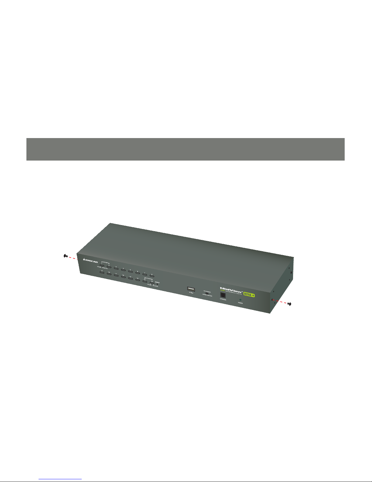
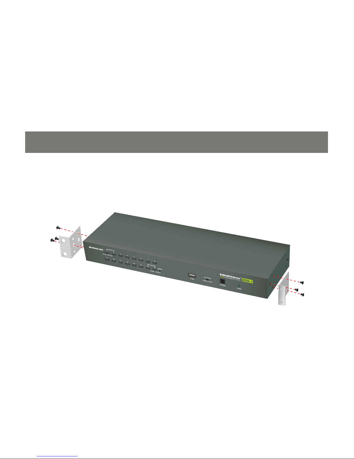
Rack Mounting
Remove the screws from the left and right sides of the switch (2 screws total) near the front of the 1.
switch.
18
19
Use the M3 x 8 Phillips hex head screws supplied with the rack mounting kit to screw the rack 2.
mounting brackets into the sides near the front of the unit.
19
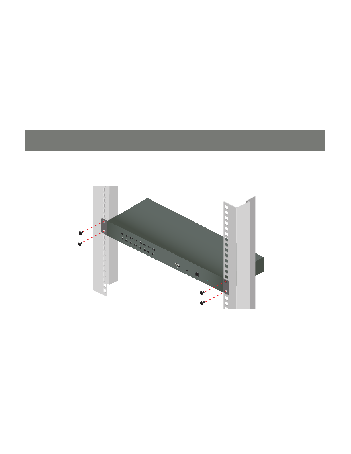
Place the KVM switch in the rack. Position it so that the holes in the mounting brackets line up with 3.
the holes in the rack. Secure the mounting brackets to the front of the rack.
1234 5 678
11121314 15 161718
PS/2-USB
CPU
CONSOLE
20
21
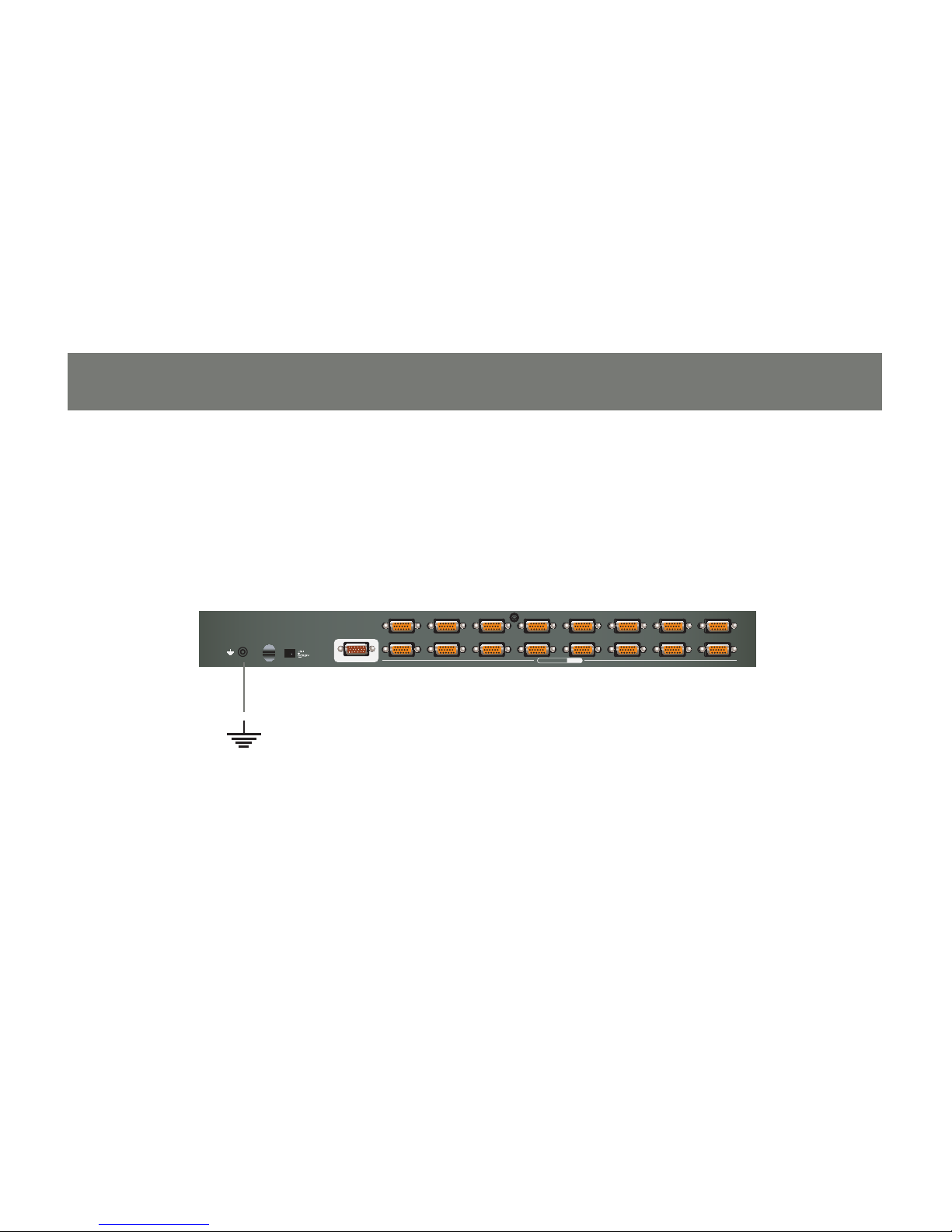
Grounding
To prevent damaging your equipment, it is important that all devices are properly grounded. Use the
included grounding wire to ground the KVM switch by connecting one end of the wire to the grounding
terminal, and the other end of the wire to a suitable grounded object.

1234 5 678
11121314 15 161718
PS/2-USB
CPU
CONSOLE
2
1
21
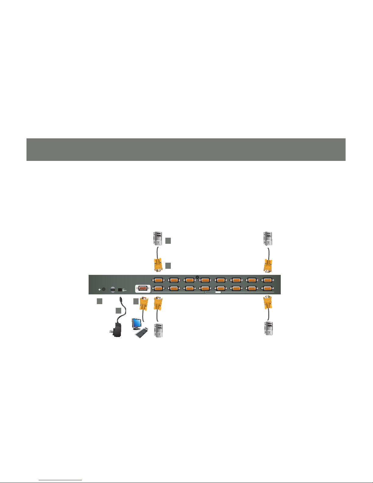
Single Level Installation
In a single level installation, only one switch is utilized. To set up, do the following:
Make sure that that switch is grounded and power has been turned off to all the computers you will be 1.
connecting.
Using the console cable provided, connect a keyboard, mouse, and monitor to the console port. Refer 2.
to the Cable Connection Diagrams on the following page.
22
23
Using a KVM cable connect it an available KVM port on the GCS1716. Make sure to connect 3.
the keyboard, video and mouse ports to the computer you are installing. Refer to the KVM Cable
Installation Diagrams on the following page.
Note: in order to use the peripheral USB port on the KVM you will need to use a USB KVM cable on
the GCS1716 and connect it to your computer.
Plug the power adapter cable into the power jack and into an AC power source.4.
Turn on the power to the computers.5.
1234 5 678
11121314 15 161718
PS/2-USB
CPU
CONSOLE
2
1
3
4
5
................................................
................................................

23
Two Levels Installation (Cascading)
Note: The cascading feature will only be available on products that will ship after January 2009. If you
purchased a GCS1716 prior to January 2009, you can add the cascading feature by simply upgrading the
Firmware. Visit www.iogear.com/support for the latest updates.
To control more computers, up to 16 additional switches can be cascaded down from the rst GCS1716.
As many as 256 computers can be controlled from a single console in a complete installation.
Note: It is recommended to use the USB KVM custom cable rather than the PS/2 one for cascading
application (see Cables Table, page 5).
To set up a cascading installation, follow the steps below:
Make sure that that switch is grounded and power has been turned off to all components you will be 1.
using.
Using the console cable provided, connect a keyboard, mouse, and monitor to the console port on 2.
the KVM. Refer to the Cable Connection Diagrams on page 25.

24
25
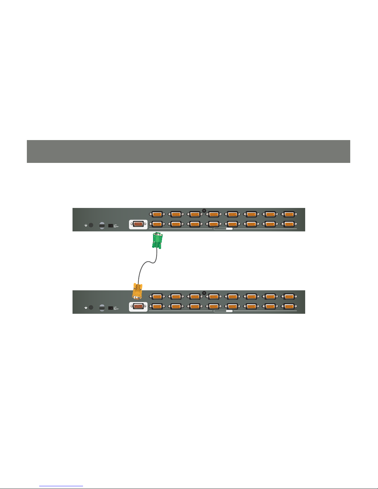
Using a cascading cable, connect the available CPU port on the upper level GCS1716, to the console 3.
port on the lower level GCS1716. Refer to the diagram on page 27.
Repeat the above step #3 for any additional switches you wish to add by connecting the second unit 4.
to another available CPU port on the rst GCS1716.
The Power On sequence requires that all second stage units be powered on rst. After they are all on, 5.
the rst stage units must be powered on next. Only after all the switches have been powered on in this
sequence, can the computers be powered on.
1234 5 678
11121314 15 161718
PS/2-USB
CPU
CONSOLE
VGAUSB PS/2
25
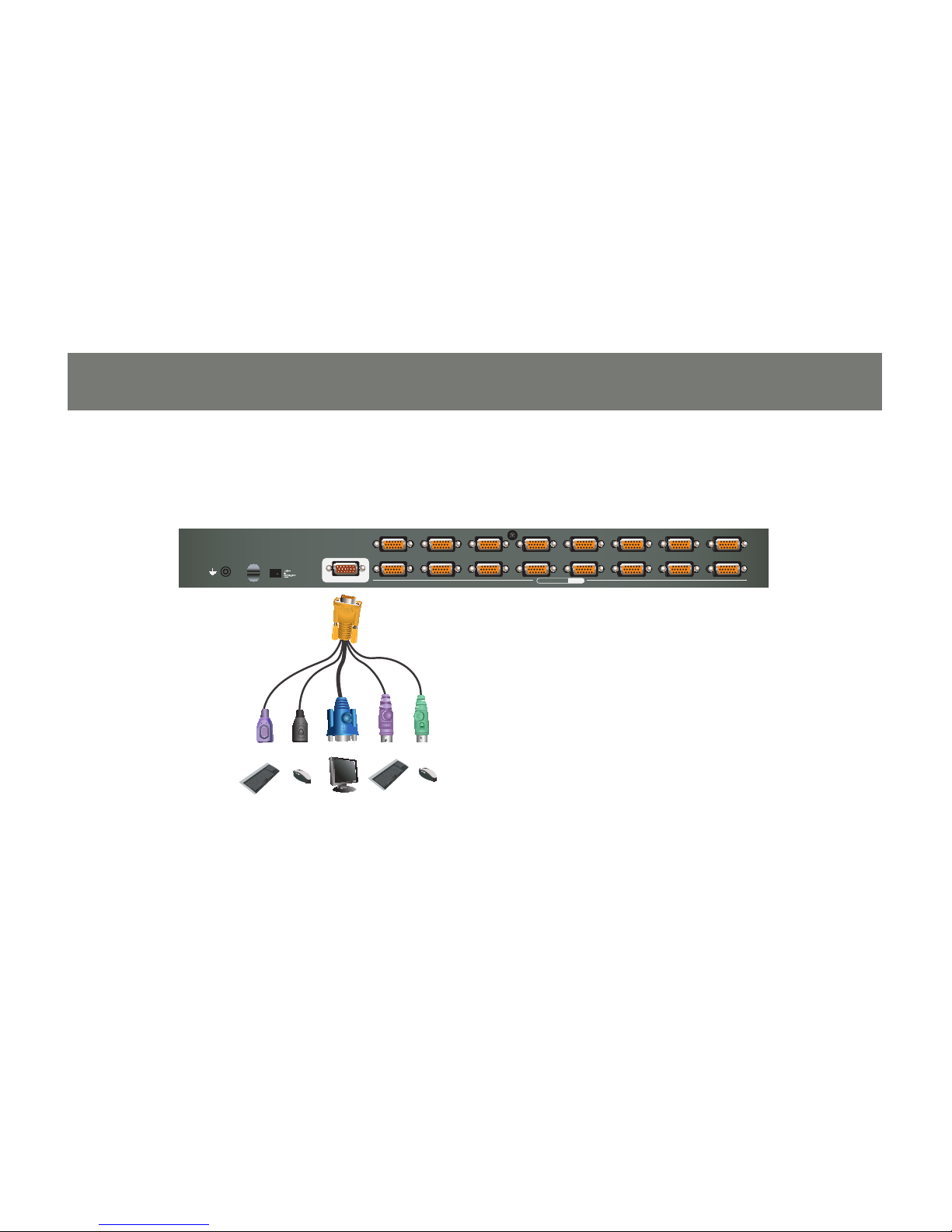
Console Cable Installation Diagram
26
27
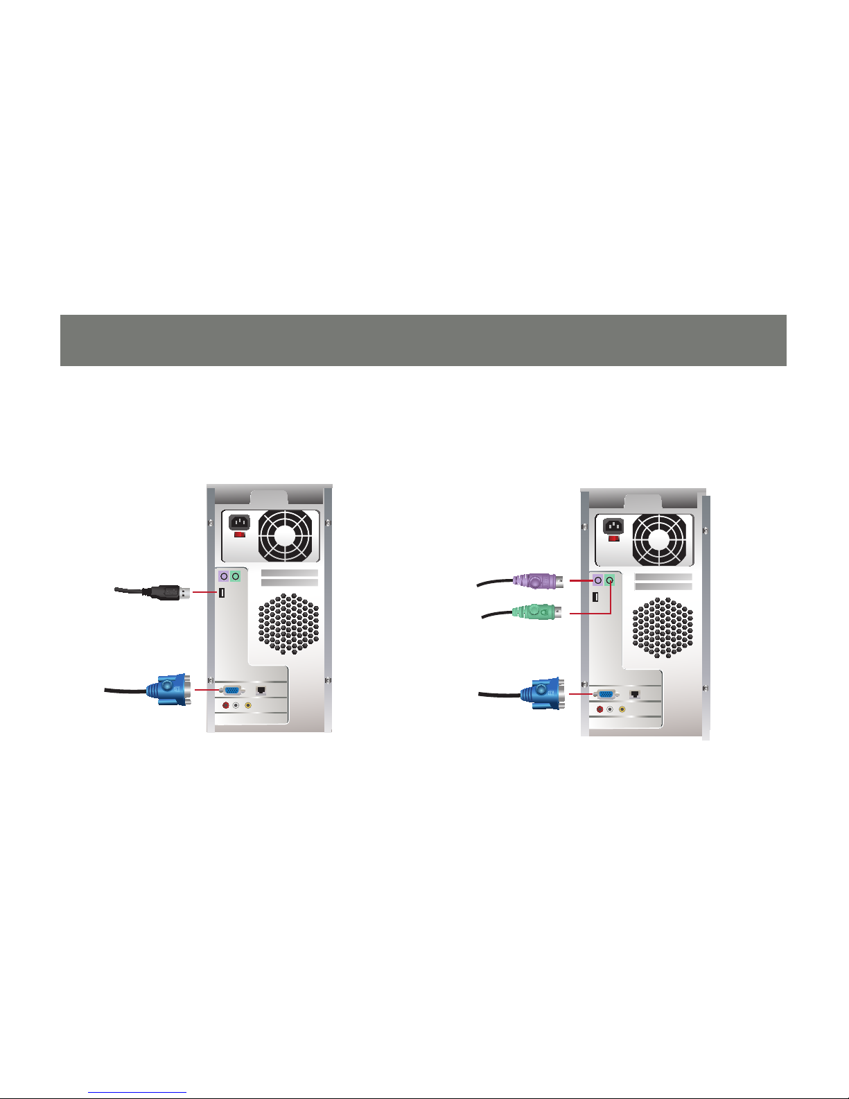
KVM Cable Installation Diagrams
USB KVM Cable Connection
PS/2 KVM Cable Connection
1234 5 678
11121314 15 161718
PS/2-USB
CPU
CONSOLE
1234 5 678
11121314 15 161718
PS/2-USB
CPU
CONSOLE
27
Cascading Installation Diagram

28
29
Basic Operation
Hot Plugging
The GCS1716 supports hot plugging – components can be removed and added back into the installation
by unplugging their cables from the ports without the need to shut the unit down. However, in order for
hot plugging to work properly, the procedures described below must be followed:
Hot Plugging KVM Ports
In order for the OSD menu to correspond to the KVM port changes, you must manually recongure the
OSD to reect the new port information.
Note: If the computer’s operating system does not support hot plugging, this function may not work
properly.
 Loading...