

Page 1

MiniView™ III
USB KVM &
Peripheral Sharing Switch
User Manual (GCS1712/1714)
Page 2

Page 3

Thank you for purchasing one of the most feature-rich keyboard, video, and mouse switches on the market.
IOGEAR’s USB KVMP switches are first-rate connectivity accessories designed to help reduce the
frustration of managing multiple computer systems. With the MiniView™ III USB KVMP series by IOGEAR,
you can access multiple computers and share USB peripheral devices from a single console (keyboard,
monitor and mouse). The MiniView™ III USB KVMP provides three convenient methods to access connected computers. Change ports easily via the push button selection switches located on the unit’s front
panel, or by entering Hot Key combinations from the keyboard or OSD (On Screen Display). Setup is fast
and easy; plugging cables into their appropriate ports is all that is entailed.
We hope you enjoy using your MiniView™ III USB KVMP switch, yet another first-rate connectivity solution
from IOGEAR.
©2002 IOGEAR. All Rights Reserved. PKG-M0014v2
IOGEAR, the IOGEAR logo, MiniView, VSE are trademarks or registered trademarks of IOGEAR, Inc. Microsoft and Windows are registered trademarks of
Microsoft Corporation. IBM is a registered trademark of International Business Machines, Inc. Macintosh, G3/G4 and iMac are registered trademarks of
Apple Computer, Inc. IOGEAR makes no warranty of any kind with regards to the information presented in this document. All information furnished here is
for informational purposes only and is subject to change without notice. IOGEAR, Inc. assumes no responsibility for any inaccuracies or errors that may
appear in this document.
Page 4

T able of Contents
T able of Contents:
Package Contents
Overview
Features
○○○○○○○○○○○○○○○○○○○○○○○○○○○○○○○
○○○○○○○○○○○○○○○○○○○○○○○○○○○○○○○
Requirements
Introduction
Installation
Operation
○○○○○○○○○○○○○○○○○○○○○○○○○○○○○○○
Appendix (HotKey)
Appendix (Troubleshooting)
Specification
○○○○○○○○○○○○○○○○○○○○○○○○○○○
○○○○○○○○○○○○○○○○○○○○○○○○○○○○○
○○○○○○○○○○○○○○○○○○○○○○○○○○○○○○
○○○○○○○○○○○○○○○○○○○○○○○○○○○○○○○
○○○○○○○○○○○○○○○○○○○○○○○○○○○○
○○○○○○○○○○○○○○○○○○○○○○○○○○
○○○○○○○○○○○○○○○○○○○○○○○○○○○○○○
Radio & TV Interference Statement
Limited Warranty
○○○○○○○○○○○○○○○○○○○○○○○○○○○○
○○○○○○○○○○○○○○○○○○○○
1
02
03
04
05
06
09
12
21
22
23
25
26
Page 5

This package contains:
1 MiniView
TM
III USB KVMP Switch
Premium Bonded USB KVMP cables (2 Cables for 2-Port, 4 Cables for 4-Port)
1 Power Adapter
1 Quick Start Guide
1 User Manual
1 Registration Card
If any items are damaged or missing please contact your dealer.
2
Package Contents
Page 6

Overview
Overview
The MiniView™ III USB KVMP Switch is a control unit that allows access to 2/4 computers from a single
console (keyboard, monitor and mouse), and it also allows sharing of up to 127 USB peripheral devices.
Before the development of the MiniView III, the only way to control multiple computer configurations from a
single console was through a complex and costly network system.
Setup is fast and easy, plugging cables into their appropriate ports is all that is entailed. There is no software
to configure, so there is no need to get involved in complex installation routines or be concerned with
incompatibility problems. Since the MiniView™ III intercepts USB keyboard input directly, it works on any
hardware platform and with all operating systems.
The MiniView
KVMP system. The MiniViewTM III USB KVMP offers push button selection switches located on the units front
panel, Hot Key controls from the USB keyboard, and an On Screen Display (OSD).
There is no better way to save time and money than with a MiniView™ III USB KVMP. By allowing a single
console to manage the attached computers, and share up to 127 USB pheripherals. The MiniView™ III USB
KVMP eliminates the expense of purchasing a separate keyboard, monitor, mouse, and extra peripheral
devices. Additionally, it saves space taken up by the additional hardware and eliminates the inconvenience
of switching from the different computer systems.
TM
III USB KVMP provides convenient methods to access the computers connected to the USB
3
Page 7

Features
Features
- Dual functional switch allows 2 to 4 USB computers to share One USB console as well as up to 127
different USB peripheral devices such as printers, scanners, and hard drives
- Conveniently switch USB peripheral devices from one computer to another through Hot Key or OSD
- Independently assign your KVM console and USB devices to any computer
- Fully Compliant with USB 1.1 specifications and delivers data at a transmission rate of up to 12 Mbps
- Complete keyboard and mouse emulation for error free booting
- Auto Scan Mode to monitor all computers
- LED display for easy status monitoring
- Superior video quality, 2048x1536, DDC2B
- Easy installation: no software required, hot pluggable
- Compact and stackable design for easy placement
- 3 Year Warranty
4
Page 8

Requirements
System Requirements
Computers with USB connections
Windows® 98, 98SE, ME, 2000, XP
Mac OS 8.6 or greater
Linux, Unix and other USB supported systems*
*Additional drivers and support may needed
Accessories:
- IOGEAR USB Hub (GUHX104) Expand your USB set up with one of our USB hubs.
- 10’ Bonded USB KVM Cable (G2L1203U), 6’ Bonded USB KVM Cables (G2L1201U)
- IOGEAR has a full line of KVM, FireWire, USB, USB 2.0, and Bluetooth™ products. Please visit our website at www.iogear.com for further information.
5
Page 9

Introduction
Introduction to MiniViewTM III USB KVMP
The MiniView III USB KVM and Peripheral Sharing Switch goes beyond your standard KVM switches by offering USB
peripheral sharing capabilities. You can save money and space by eliminating the need for not only extra monitors,
keyboards and mice, but also on peripheral devices such as printers, scanner, zip drives, etc. Up to 127 different USB
devices can be daisy chained from this KVMP switch.
Setup is fast and easy; just plug the cables into their appropriate ports. There is no software to configure so there is no
need to get involved in complex installation routines or be concerned with incompatibility problems. This unit also features
USB Sniffing Technology which allows complete USB keyboard and USB mouse emulation for error free booting, Hot Ke y
control and OSD (On Screen Display) to conveniently switch USB peripheral devices from one computer to another.
The MiniView
(1) using the port selection buttons on the front panel of each unit; (2) entering
and (3) selecting from on-screen menus through the On Screen Display (OSD) feature. In addition, a powerful
Scan
There is no better way to save time and mone y than with a MiniVie wTM III USB KVMP. By allowing the MiniViewTM III USB
KVMP to manage all the attached computers, there is no need to purchase a separate keyboard, monitor, and mouse for
each computer, and expensive USB peripherals saving an enormous amount of space. It also eliminates the inconvenience
and wasted effort involved in constantly moving around from one computer to another.
TM
III USB KVMP provides three convenient methods to access any computer connected to the system:
Hot Key
combinations from the keyboard;
Quick View
feature allows you to auto scan and monitor the activities of all operating computers on the installation one by one.
6
Page 10
Introduction
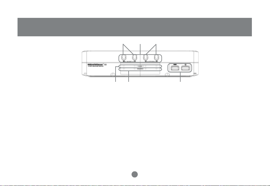
1
Front View
3 42
1. CPU port indicator/selection buttons
2. On-line LED indicators
3. Selected LED indcators
4. USB T ype A console port for USB keyboard and mouse
5. Pressing these 2 buttons will simultaneously invoke Auto Scan Mode
6. Pressing these 2 buttons will simultaneously reset the KVM
7
56
Page 11

Introduction
Back View
1. Port for power adapter
2. V GA console port for your monitor
3. USB T ype A ports for peripheral devices
4. USB T ype B ports to connect your computers VIA our premium bonded USB KVM cables
5. V GA ports to connect to your computers VIA our premium bonded USB KVM cables
34
25
1
8
Page 12

Installation
Setup and Installation
Step. 1 (Power Adapter / Console Connection)
* Before you begin, please make sure that the power to all devices has been turned off.
1. Plug your USB Mouse, USB Keyboard, and Monitor into the console area at the front of the KVMP Switch
2. Plug the Monitor into the console area at the back of the switch, and then the power adapter into the power adapter port.
9
Page 13

Setup and Installation
Step. 2 (Cable Connection)
1. Connect the cables that came with the MiniView™ III USB KVMP switch to the KVMP switch's CPU ports.
10
Installation
Page 14

Installation
Setup and Installation
Step. 3 (Cable Connection)
1. Connect the other end of the cables that came with the MiniView™ III USB KVMP switch to your computer.
2. Once complete, turn the USB KVMP switch on.
3. Connect the USB peripheral devices to the a vailable device port on KVMP.
4. Then turn on the power to the connected computers and devices.
11
Page 15

Operation
Operation
Controlling the computers on your MiniViewTM III USB KVMP from a single console could not be easier. The switch has three
port selection methods providing you with instant access to your computers.
- Manual Port Selection: Simply press the appropriate Port Selection Button on the front panel. After you press the button, the Selected LED will light
up to indicate that the port is currently selected.
- HotKey Port Selection:
1) Select CPU: Press the following keys in sequence, [Ctrl]+[Shift]+[Alt]+CPU Port ID+[Enter]
2) Assign peripherals: Press the following keys in sequence, [Ctrl]+[Shift]+[Alt]+[F#] (# is the ID of the computer the peripheral is assigned to.)
- OSD (On Screen Display):
It is a menu driven interface to handle computer and peripheral switching
HotKey Operation
Selecting the Active Port
Each CPU port is assigned a numeric ID (1-4). Y ou can directly access an y computer connected to the KVMP with a Hot Key combination that specifies
the ID of the CPU port.
Press and release each of the following keys, in order, until complete:
[Ctrl] + [Shift] + [Alt] + CPU Port ID, then press [ENTER] to complete the process.
12
Page 16

Operation
Assigning USB Peripherals
The two USB device ports can be assigned to any computer
connected to the MiniView III through Hot Keys by pressing the
following keys in sequence, [Ctrl] + [Shift] + [Alt] + [F#] (# is the ID of
the computer the peripheral is assigned to.)
For instance, to assign peripheral for computer 2, press the following
keys in sequence, [Ctrl] + [Shift] + [Alt] + [F2].
Hot Key Summary Table
13
Page 17

Operation
OSD Operation
OSD (On Screen Display) is a menu driven interface to handle the computer and peripheral switching procedures. T o activ ate the OSD, tap [Ctrl] twice.
(Note: If using [Ctrl] key conflicts with applications running on any of the computers, you can change the OSD Activation Hot Key to [Scroll Lock] [Scroll
Lock] by F10 Set Up. Please refer to F10 SETUP for details)
When you invoke the OSD , a screen similar to the one below appears:
The OSD always starts with the highlight bars at the last position selected regardless which selection method was used.
14
Page 18

Operation
OSD Navigation
To e xit from the OSD manual at any time, press [ESC].
To assign the console (k eyboard, monitor and mouse) to any computer , use F1 and F4 keys to move the CPU P ort Highlight Bar through the list. When
you reach the desired port, press [ENTER]. An icon of pointing hand indicates the active port.
To assign the peripheral de vice ports to any computer, use F5 and F8 keys to mov e the Device P ort Highlight Bar through the list. Press [ENTER] when
you reach the desired port. An icon of pointing hand indicates the active port.
OSD Menu Headings
gnidaeH noitanalpxE
.noitallatsniehtnostropUPCehtllarofsrebmunDItroPehtstsilnmulocsihT
NP
CP
MVK
BSU
EMAN
slarehpirepBSUeht
nmulocehtnisraeppa
]retnE[sserpneht,tropgnidnopserrocs'tiotraB
eniLnOeradnanOderewoPeratahtsretupmocehtllastsiL
)esuomdna,rotinom,draobyek(sucofelosnoc
15
thgilhgiHehtevomotsiretupmocralucitrapasseccaotdohtemtselpmisehT
ehtsahretupmochcihwsetacidninmulocsihtninoci'dnahgnitniop'A
otsseccasahretupmochcihwsetacidninmulocsihtninoci'dnahgnitniop'A
emansti)71egapnoPUTES01Fees(emananevigneebsahtropafI
Page 19

Operation
Navigation:
To exit from the OSD menu at any time press [ESC]
Use the Up and Down arrow keys to move through the list one line at a time
Use [PG UP] and [PG DOWN] to move up or down through the list, one screen at a time
To activate a port move the Highlight Bar to the desired port and press [ENTER]
Function Keys:
F1 PREV KVM:
Pressing [F1] switches console from the currently active computer to the previous one on the installation. Keep on pressing [F1] to move the Highlight Bar
until it is on the desired computer, then press [ENTER].
F4 NEXT KVM:
Pressing [F4] switches console from the currently active computer to the next one on the installation. Keep on pressing [F4] to move the Highlight Bar until
it is on the desired computer, then press [ENTER].
F5 PREV Device:
Pressing [F5] switches USB devices from the currently active computer to the previous one on the installation. Keep on pressing [F5] to move the Highlight
Bar until it is on the desired computer, then press [ENTER].
F8 NEXT Device:
Pressing [F8] switches USB devices from the currently active computer to the next one on the installation. Keep on pressing [F8] to move the Highlight Bar
until it is on the desired computer, then press [ENTER].
16
Page 20

Operation
F9 AUTO SCAN:
Pressing [F9] initiates Auto Scan, in which each computer is displayed for the amount of time set with Scan Duration under the F10 SETUP functions.
Press [Space Bar] will stop Auto Scan.
(Note: 1. As each computer is scanned, an S appears in front of the Port ID display indicates that it is being scanned. 2. If the scanning stops on an empty
port, or on a powered off computer, the monitor will turn blank, mouse and keyboard will have no eff ect. To recover, key in the Hot Ke y sequence for an y
Port ID that has an active computer attached.)
F10 SETUP: (See T able on Next P age)
Pressing [F10] brings up the OSD configuration menu. T o change the setting,
1.Move the Highlight Bar through the list using the Up and Down Arrow keys, then press [ENTER].
2.On the sub menu that appears, move the Highlight Bar to your choice and press [ENTER].
An icon of pointing hand indicates the current choice. The explanation of all choices is given in the table below:
17
OSD Operation
Page 21

gnitteS noitcnuF
NOITARUD
NOITISOP
See Continuous T able Next P age
YALPSIDLENNAHCTES
YALPSIDLENNAHCTES
EMANRETUPMOCTIDE
ELOSNOCKCOL
Operation
nOsyawlAro;sdnoces
.unembusteSehtotnruterdnanotisopehtkcolot]retnE[sserpneht
.]csE[sserp,egnahceht
.elosnoCehtkcolnU/kcoLlliw]retnE[
18
3;ecalpnekatsahegnahctroparetfarotinomehtnosyalpsidDItroPagnolwohsenimreteD
gP,pUgP,syeKworrAehtesU.neercsehtnosraeppaDItroPehterehwnoitisopotuoyswollA
,yalpsidDItroPehtnoitisopot,)ffokcoLmuNhtiwdapyekciremunehtno(5dna,dnE,emoH,nD
.emananevigebnactropyreve,tropralucitrapaotdehcattasiretupmochcihwrebmemerplehoT
21otpuebyamemanhcaE.semantropeteledro,yfidom,etaercotuoyswollanoitcnuftidEehT
trobaoT.tceffeekategnahcehtevahot]retnE[sserp,gnitidehsinifuoynehW.htgnelnisretcarahc
.syalpsidneercsrotinomtnerrucehtylno,dekcolsielosnoCehtnehW.elosnoCehtskcolnU/skcoL
.dekcolsielosnocehttahtetacidniotwodniwDSOehtforenrocthgirpotehtnisraeppazzzA
,troptnereffidaothctiwsotstpmetta;tceffeonevahelosnocehtmorfnoitamrofnitupniotstpmettA
otyawylnoehT.rehtietceffeonevah,hctiwslaunamehtgnisserpybroelosnoCehtmorfrehtie
tsumuoy,tesneebsahdrowssapafI.elosnoCehtgnikcolnUybsisretupmocehtotsseccaniager
gnisserp,tesneebsahdrowssaponfI.elosnoCehtkcolnU/kcoLotredronidrowssapehtedivorp
Page 22

Operation
gnitteS noitcnuF
DROWSSAPTES
NOITARUDNACSTES
YEKTOHGNITAVITCADSOTES
Factory Default Settings: (See T able Below)
gnitteS tluafeD
noitaruDyalpsiD
edoMyalpsiD
noitaruDnacS
nOsyawlA
sdnoceS5
.sseccaelosnoclortnocotredronidrowssapatesotuoyswollanoitcnufsihT
.)9-0,Z-A(srebmundnasrettelfonoitanibmocynafo
.tcerrocsititahtmrifnocotredro
:erasnoitpoehT.edoMnacS .sdnoces06dna,04,03,02,51,01,5,3
.desuebdluohsnoitpokcoLllorcseht,esachcihw
emaNtroPehtsulprebmuNtroPehT
19
tahtneercsahtiwdetneserperauoY.]retnE[sserpneht,drowssaP:otrabthgilhgihehtevoM.1
tsisnocnacdna,gnolsretcarahc8otpuebyamdrowssapehT.drowssapruoyniyekotuoyswolla
niniaganidrowssapehtyekotdeksaerauoY.]retnE[sserpneht,drowssapwenehtniyeK.2
drowssapweneht,hctamseirtneowtehtfI.]retnE[sserpneht,niagadrowssapwenehtniyeK.3
royfidomoT.gninnigebehtmorfniagatratstsumuoy,hctamtonodseirtneehtfI.detpeccasi
.srebmunrosrettellaudividniesareotyekecapskcabehtesu,drowssapsuoiverpaeteled
otuAnistropdetcelesehthguorhtselcyctisatrophcaenosllewdyalpsidehtgnolwohsenimreteD
ehT.]kcoLllorcS[]kcoLllorcS[ro]lrtC[]lrtC[:noitcnufDSOehtsetavitcayektoHhcihwstceleS
ni,sretupmocehtnogninnursmargorphtiwtcilfnocyamsihttub,noitanibmocyeklrtCehtsitluafed
Page 23

Operation
OSD Security
The OSD provides a password security in order to prevent unauthorized access to the computers . T o set a pass word:
1. Press [F10] to bring up the SET UP menu;
2. Move the Highlight Bar to PASSWORD, then press [ENTER];
3. Key in the new password, then press [ENTER]; (the password may be up to 8 characters long, and can consist of any combination of letters and
number (A – Z, 0 – 9);
4. Key in the new password for confirmation, then press [ENTER].
If the two entries match, the new password is accepted and screen displays the following message:
If the entries do not match, the screen will display:
You will have to start from the very beginning of the process again.
5. T o modify or delete a previous pass word, access the Pass word function in steps 1 and 2, then use the backspace or delete key to erase the
individual letters or numbers.
SET P ASSWORD OK
PASSWORD NOT MATCH
20
Page 24

Appendix
HotKey Commands Summary (Model: GCS1712/1714)
21
Page 25

Appendix
Troubleshooting (Model: GCS1712/GCS1714)
Note: If the unit appears to be operating erraticallly, chec k all cables for damage and to be sure that they are properly connected. If you are operating
under nonpowered mode, use the external power adapter.
motpmyS esuaCelbissoP noitcA
roivahebcitarrE
syektoHgnisserP
esnopseronsteg
tonesuoM
gnidnopser
If you need further assistance please check out our IOGEAR Tech Info Library (T.I.L.) at www.iogear.com/support for the latest tips, tricks, and troubleshooting. The
IOGEAR T.I.L. was designed to provide you with the latest technical information about our products. Most of the answers to your questions can be found here, so
please try it out before contacting technical support.
Technical Support is available Monday through Friday from 8:00am to 5:00pm PST and can be reached at 949-453-8782.
rewophguonegniviecertontinU
noitarepoderewop-flesrednu
ehtmorfnoitcennocehT
tegratehtottropdetceles
nekorbneebsahretupmoc
teserdraobyekreporpmI
teserIII™weiViniMreporpmI
teseresuomreporpmI
.rewop
detcennocylreporpllaerayehterusekamotselbacehtkcehC
nikcab
nokcab
DItroPehtnigniyekyltcerrocnI
ni
22
lanretxeedivorpottinuehthtiwdeilppussawtahtretpadArewoPehtesU
tigulpneht,troPdraobyeKelosnoCehtmorfrotcennocdraobyekehtgulpnU
mehtgninruterofebsdnoceseviftiawdnatinuIII™weiViniMehtfforewoP
eb,noitanibmoc]tlA[+]tfihS[+]lrtC[ehthtiwnoitcnufyektoHehtgnikovniretfA
yekhcaerofdnocesenonihtiw]retnE[sserpdnaDItroPehtniyekoterus
kcabtigulpneht,troPesuoMelosnoCehtmorfrotcennocesuomehtgulpnU
Page 26

Specification
Product Specification (MODEL: GCS1712/1714)
noitcnuF 2171SCG 4171SCG
snoitcennoCretupmoC
noitceleStroPUPC
noitceleStroPBSU
sDEL
srotcennoCelosnoC
rotcennoCUPC
eniLnO )egnarO(2 )egnarO(4
detceleS )neerG(2 )neerG(4
draobyeKrotcennoCAepyTBSUx1
esuoMrotcennoCAepyTBSUx1
oediVelamef51-BDDHx1
BSU srotcennoCBepyTBSUx2 srotcennoCBepyTBSUx4
oediV AGVelam51-BDDHx2 AGVelam51-BDDHx4
24
DSO,syeKtoH,sehctiwSlenaPtnorF
DSO,syeKtoH
23
Page 27

Product Specification Contd. (MODEL: GCS1712/1714)
noitcnuF 2171SCG 4171SCG
slarehpirePBSU
noitalumE
lavretnInacS
noituloseR
noitpmusnoCrewoP
erutarepmeTgnitarepO
erutarepmeTegarotS
ytidimuH
gnisuoH
thgieW
)HxWxL(snoisnemiD
eniLnO srotcennoCAepyTx2
sehctiwSnoitceleStroP
draobyeKBSU
esuoMBSU
C°04-5
C°06-02-
HR%08-0
lateM
g094 g007
Specification
nottuBhsuPgnikcoL-noNx1 snottuBhsuPgnikcoL-noNx4
).ces5;tluafeD(.sces06,04,03,02,51,01,5,3
B2CDD;6351x8402otpU
).xam(W58.0;V5CD ).xam(W52.1;V5CD
mm24x5.47x031 mm24x5.47x002
24
Page 28

Radio & TV Interference Statement
Radio & TV Interference Statement
WARNING!!! This equipment generates, uses and can radiate radio frequency energy and, if not installed and
used in accordance with the instruction manual, may cause interference to radio communications. This
equipment has been tested and found to comply with the limits for a Class B computing device pursuant to
Subpart J of Part 15 of FCC Rules, which are designed to provide reasonable protection against such
interference when operated in a commercial environment. Operation of this equipment in a residential area is
likely to cause interference, in which case the user at his own expense will be required to take whatever
measures may be required to correct the interference.
25
Page 29

Limited Warranty
Limited Warranty
IN NO EVENT SHALL THE DIRECT VENDOR’S LIABILITY FOR DIRECT, INDIRECT, SPECIAL, INCIDENTAL OR CONSEQUENTIAL DAMAGES RESULTING FROM THE USE OF THE PRODUCT, DISK OR ITS
DOCUMENTATION EXCEED THE PRICE PAID FOR THE PRODUCT.
The direct vendor makes no warranty or representation, expressed, implied, or statutory with respect to the
contents or use of this documentation, and especially disclaims its quality, performance, merchantability, or
fitness for any particular purpose.
The direct vendor also reserves the right to revise or update the device or documentation without obligation to
notify any individual or entity of such revisions, or updates. For further inquires please contact your direct
vendor.
26
Page 30

Page 31

Page 32

Contact info.
23 Hubble • Irvine, CA 92618 • (P) 949.453.8782 • (F) 949.453.8785 • www.iogear.com
 Loading...