

Page 1

MiniV iew™ ULTRA
8 Port KVM Switch (GCS138 Installation Manual)
Page 2

©2001 IOGEAR. All Rights Reserved.
IOGEAR, the IOGEAR logo, MiniView, and VSE are trademarks or registered trademarks of IOGEAR, Inc.
Microsoft and Windows are registered trademarks of Microsoft Corporation. IBM is a registered trademark of International Business Machines, Inc.
Macintosh, G3/G4 and iMac are registered trademarks of Apple Computer, Inc. IOGEAR mak es no warranty of an y kind with regards to the
information presented in this document. All information furnished here is for informational purposes only and is subject to change without notice. IOGEAR,
Inc. assumes no responsibility for any inaccuracies or errors that may appear in this document.
Page 3

Thank you for purchasing one of the most feature-rich KVM switches on the market. IOGEAR’s KVM
switches are first-rate connectivity accessories designed to help reduce the frustration of managing multiple
computer systems. With the MiniView™ ULTRA series by IOGEAR, you can access multiple computers
from a single console(keyboard, mouse and monitor). The MiniView™ ULTRA provides three convenient
methods to access connected computers. Change ports easily via the push button selection switch located
on the front of the KVM, or by entering Hot Key combinations from the keyboard, or through the OSD (OnScreen-Display). Setup is fast and easy; plugging cables into their appropriate ports is all that is entailed.
We hope you enjoy using your MiniView™ ULTRA KVM Switch, yet another first-rate connectivity solution
from IOGEAR.
Page 4

Page 5

T able of Contents:
T able of Contents
Package Contents
Overview
Features
○○○○○○○○○○○○○○○○○○○○○○○○○○○○○○○
○○○○○○○○○○○○○○○○○○○○○○○○○○○○○○○
Requirements
Introduction
Installation
○○○○○○○○○○○○○○○○○○○○○○○○○○○
○○○○○○○○○○○○○○○○○○○○○○○○○○○○○
○○○○○○○○○○○○○○○○○○○○○○○○○○○○○○
○○○○○○○○○○○○○○○○○○○○○○○○○○○○○○○
On-Screen-Display (OSD) Operation
Power Off
Port ID Numbering
Port Selection
Function Keys
Appendix (Troubleshooting)
Specification
○○○○○○○○○○○○○○○○○○○○○○○○○○○○○○○
○○○○○○○○○○○○○○○○○○○○○○○○○○○
○○○○○○○○○○○○○○○○○○○○○○○○○○○○○○
○○○○○○○○○○○○○○○○○○○○○○○○○○○○○
○○○○○○○○○○○○○○○○○○○○○○○○○
○○○○○○○○○○○○○○○○○○○○○○○○○○○○○○
Radio & TV Interference Statement
Limited Warranty
○○○○○○○○○○○○○○○○○○○○○○○○○○○○
○○○○○○○○○○○○○○○○○○○
○○○○○○○○○○○○○○○○○○○○
02
03
04
05
07
12
19
23
25
26
28
35
37
39
40
Page 6

Package Contents
This package contains:
1 MiniView™ ULTRA KVM switch (GCS138)
1 User Manual
1 Registration Card
1 Power Adapter
1 Quick Start Guide
If any items are damaged or missing please contact your dealer.
2
Page 7

Overview
Overview
The MiniView™ ULTRA GCS138 KVM (Keyboard, Video, Mouse) Switch is a control unity that allows access
to eight computers from a single console (keyboard, mouse and monitor). Before the development of the
MiniView™ ULTRA, the only way to control multiple computer configurations from a single console was
through a complex and costly network system.
setup is fast and easy, plugging cables into their appropriate posts is all that is entailed. We have arrange so
the 2 PS/2 console ports are on the front of the unit for easy and convenient access. There is no software to
configure, so there is no need to get involved in complex installation routines or be concerned with incompatibility problems. Since the MiniView™ ULTRA GCS138 intercepts keyboard input directly, it works on any
hardware platform and with all operating systems.
The MiniView™ ULTRA GCS138 provides two convenient methods to access the computers connected to
the system using push button selection switches located on the units front panel and entering Hotkey
combinations from the keyboard.
There is no better way to save time and money than with a MiniView™ ULTRA GCCS138. By allowing a
single console to manage the attached computers, the MiniView™ ULTRA GCS138 eliminates the expense
of purchasing a separate keyboard, monitor and mouse. Additionally, it saves space taken up by the
additional hardware and eliminates the inconvenience of switching from the different computer systems.
3
Page 8

Features
Features
- Cascadable To Three Levels - Control Up to 512 PCs From a Single Console
- No Software Required
- PC Selection Via Front Panel Switches, HotKeys, or OSD (On Screen Display)
- Quick View Scan Feature for Monitoring Selected PCs
- PS/2 and Serial Mouse Emulation Provided For System Bootup
- Console’s PS/2 Mouse Controls All Connnected PCs - Even Those With Serial Mice
- PS/2 Compatible Mouse Support - Microsoft Intellimouse Pro, Logitech FirstMouse Support*
- SVGA, VGA and Multisync Monitor Support
- Superior Video Quality; 1920 x 1440; DDC, DDC2, DDC2B
- LED Display For Easy Status Monitoring
- Rack Mountable in 19” System Rack
- Hot Pluggable - Add or Remove PCs for Maintenance Without Powering Down the Switch
* 1. PS/2 compatible mouse support is for three button (wheel) mice.
2. The Logitech Mouse Ware program’s
change device
procedure does not work on Microsoft NT systems.
4
Page 9

Requirements
Requirements
Console
- A VGA, SVGA, or Multisync monitor capable of the highest resolution that you will be using on any PC in the installation
- A PS/2 Style Mouse
- A PS/2 Style Keyboard
PC: The following equipment must be installed or on board each PC that is to be connected to the system:
- A VGA, SVGA or Multisync card.
- Either a 6-pin mini-DIN (PS/2 style), or DB-9 (standard serial), mouse port
- Either a 6-pin mini-DIN (PS/2 Style) keyboard port with _5V DC on pin 4 and Ground on pin 3, or a 5-pin DIN (AT Style) k eyboard port with +5V DC on
pin 5 and ground on pin 4.*
5
Page 10

Requirements
NOTE:
1. If your PC uses a standard A T style k eyboard sock et you will need to purchase a PS/2-to-A T k eyboard adapter (Part No. 2A-106, or an y standard
keyboard adapter), in order to plug the cable into the computer’s keyboard port.
2. If your PC uses standard 9 pin serial port for the mouse, you will need to purchase a PS/2-to-Serial mouse adapter (Part No.2A-105; a standard mouse
adapter will probably not work). In order to plug the cable into the computer’s serial port.
3. Because of the wiring and pin assignments, you cannot use a Serial-to-PS/2 adapter at the end that plugs into the GCS138.
6
Page 11

Introduction
Introduction on MiniViewTM ULTRA
The MiniView
monitor, and mouse). Bef ore the de v elopment of the MiniView
tions from a single console was through a complex and costly network system. No w, with the MiniView
easily access multiple computers in a simple and cost effectively manner.
One MiniViewTM ULTRA can control up to eight PCs. Units can be cascaded to three levels, which means that as many as 73
MiniViewTM ULTRA units can control up to 512 PCs - all from a single console.
Setup is fast and easy; just plug the cables into their appropriate ports. There is no software to configure so there is no
need to get involved in complex installation routines or be concerned with incompatibility problems. Since the MiniView
ULTRA accepts keyboard input directly, it works virtually any hardware platform with all operating systems.
The MiniViewTM ULTRA provides three convenient methods to access any PC connected to the system: (1) using the port
selection buttons on the front panel of each unit; (2) entering
on-screen menus through the On Screen Display (OSD) feature. In addition, a powerful
to auto scan and monitor the activities of all operating PCs on the installation one by one.
There is no better way to sav e time and money than with a MiniViewTM UL TRA. By allo wing the MiniViewTM UL TRA to manage
all the attached PCs, there is no need to purchase a separate keyboard, monitor, and mouse for each PC, saving an
enormous amount of space. It also eliminates the inconvenience and wasted effort involved in constantly moving around
from one PC to another.
TM
UL TRA GCS138 is a KVM s witch that controls access to multiple computers from a single console (k e yboard,
TM
UL TRA, the only w a y to control multiple computer configura-
Hotkey
combinations from the keyboard; and (3) selecting from
Quick View Scan
7
TM
UL TRA, y ou can
feature allows you
TM
Page 12
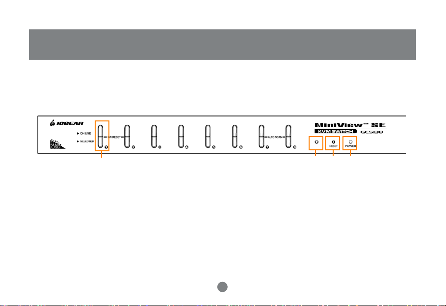
Introduction
Front View
1, 2
4 3 5
1. Port LEDs
On Line: Lights BLUE to indicate that the PC attached to the corresponding port is up and running. If the LED is flashing,
it indicates that the Port is being used for Cascading to another MiniView
TM
ULTRA switch. Selected: Lights Green to
indicate the current selected port. The LED is steady under normal conditions, but flashes when its port is accessed
under Auto Scan mode.
2. Port Selection Switches
Press a switch to access the PC attached to the corresponding port. Pressing Buttons 1 and 2 simultaneously for 3
seconds performs a Keyboard and Mouse reset; pressing Buttons 7 and 8 simultaneously starts Auto Scan Mode.
8
Page 13

Introduction
3. MiniView
To reset the MiniView
TM
ULTRA Reset
TM
ULTRA, use a thin object (such as the end of a paper clip, or a ballpoint pen), to press this recessed
switch in to initiate a warm reset. If the switch is kept in for longer than three seconds, a cold reset takes place.
4. Sound Opening
System sounds (beeps,etc.), are emitted from this opening.
5. Power LED
Lights to indicate that the MiniView
TM
UL TRA is receiving po w er.
9
Page 14
Introduction
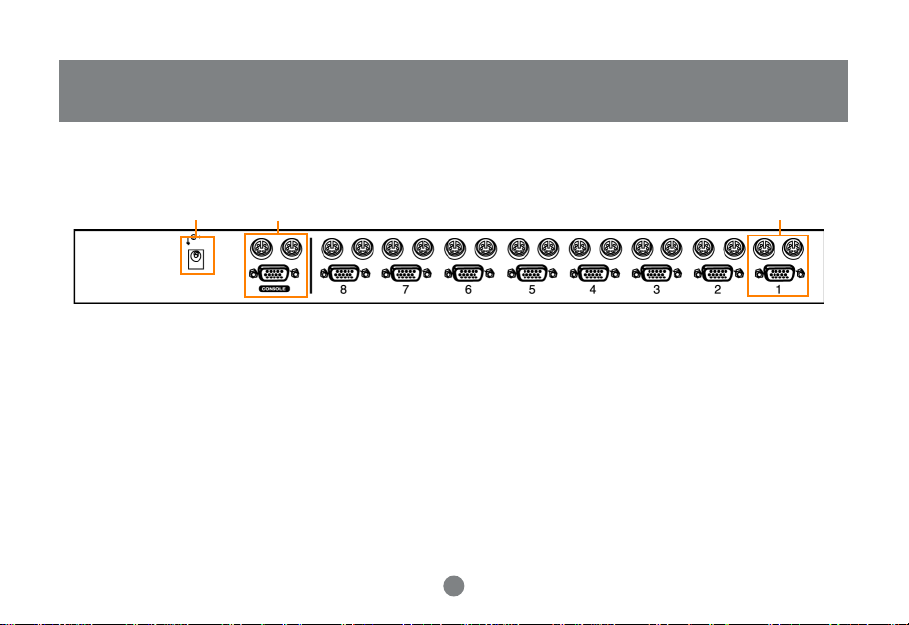
Back View
1
2
1. Power Jack
The power adapter plugs in here.
2. Console Port Section
If this is a first station unit. Your monitor, keyboard and mouse plug in here.
If this is a daisy chained unit. The cables that link back to a port on a higher MiniView
3. Console Port Section
The cables that link to the PCs plug in here.
10
TM
ULTRA unit plug in here.
3
Page 15

Introduction
11
Page 16

Installation
Setup and Installation (Power Adapter)
Step. 1 (Power Adapter Connection)
* Before you begin, please make sure that the power to all devices has been turned off.
Connecting your console to the MiniView
MiniViewTM UL TRA power adapter.
NOTE: T o pre vent damage to your installation due to ground potential diff erence, make sure that all devices on the installation are properly grounded.
Consult your dealer for technical details, if necessary .
The Unit is designed to be non-powered (no external power required). Generally speaking, the only time that external power is
required is when you daisy chain it, or if operation becomes erratic because the unit isn’t obaining enough power from the
computer connections.
If you choose to use external power, plug the adapter into a standard surge protector, then plug the cable into the MiniView
UL TRA Pow er Jack.
TM
UL TRA. You will need y our V GA monitor, PS/2 mouse, PS/2 keyboard and the
12
TM
Page 17

Setup and Installation (Console Port Connection on KVM Switch)
2
2
1
Step. 2 (Console Connection)
1. Connect the end of your monitor cab le into the console side of the MiniView
2. Plug in your PS/2 mouse and PS/2 k eyboard into their designated ports on the console side of the MiniView
13
TM
UL TRA video port.
Installation
TM
ULTRA.
Page 18

Installation
Setup and Installation (CPU Port Connection on KVM Switch)
2
2
1
Step. 3 (CPU Port Connection)
TM
1. Connect the f emale end of your IOGEAR video cab le into the male video port on the MiniView
port number.
2. Plug in the PS/2 mouse and PS/2 keyboard connectors located on the same end as the female video connector. The
cables have images on them indicating that they are for the keyboard or mouse.
14
UL TRA labeled with a CPU
Page 19

Setup and Installation (Port Connections on back of Computer)
3
Step. 4 (Connecting the PCs)
Installation
3. Plug in the remaining PS/2 mouse and PS/2 keyboard connectors into your PC’s keyboard and mouse ports.
4. Repeat steps 1-3 for any additional computers you wish to connect to the MiniView
NOTE: Y ou ma y need to attach a PS/2 to A T adapter on the keyboard cab le if your computer has an A T k eyboard connection. Also , if you do not hav e a
PS/2 mouse port you will need to use our PS/2 to Serial adapter to connect the mouse cable. You can use any manuf acturer’ s PS/2 to A T
adapter but you must use our PS/2 to Serial adapters for the mouse.
15
TM
UL TRA.
Page 20

Installation
Setup and Installation (Cascading MiniViewTM ULTRA)
2
2
1
Step. 5 (Cascading MiniView
* Use standard IOGEAR PS/2 cables to cascade units.
TM
Ultra Units)
1. Connect the female end of your IOGEAR video cable into the male video port on an available CPU section of the
MiniViewTM UL TRA.
2. Plug in the PS/2 keyboard connectors located on the same end as the female video connector. The cables have images
on them indicating that they are for the keyboard or mouse.
16
Page 21

Installation
Setup and Installation (Cascading MiniViewTM ULTRA)
4
4
3
Step. 6 (Cascading Cont.)
TM
3. Now plug the male end of the video cab le into the f emale video port on the secondary MiniView
4. Plug in the remaining PS/2 mouse and PS/2 keyboard connectors into the keyboard and mouse ports on the secondary
MiniView
5. Plug the
TM
UL TRA console section.
power adapter into a standard surge protector , then plug the adapter cab le into each MiniView
Jack.
Congratulations! You have now completed the installation
17
UL TRA console section.
TM
UL TRA P o wer
Page 22

Cascading in pyramid format
(Cascading Diagram)
○○○○
○○○○○○○○○○○○○○○○○○
○○○○○○○○○○○○○○○○○○○○○○○○○
○○○○○○○○○○○○○○○○○○○○○○○○○○○○
Step. 7 (Cascading In Pyramid format)
- Red connection indicate level 1 (8 computers)
- Green connection indicate level 2 (64 computers)
- Orange connection indicate level 3 (512 computers)
○○○
○○
○○
○○○
18
Page 23

OSD Operation
OSD Operation
On Screen Display (OSD), provides a menu driven interface to handle the PC switching procedure. Although Hotkey
Switching still works, using OSD is a great deal more convenient - especially in large, daisy chained installations where a
great number of PCs are connected to a several MiniViewTM ULTRA GCS138 units, and it is difficult to keep track of which
port a particular PC is attached to.
* All operations start from the OSD Main Menu. T o pop up the Main Menu , press the contr ol key twice ([Ctrl] [Ctrl]):
Note: You can use either the left or r ight Ctrl keys, but they must both be on the same side (both left, or both right).
OSD always starts in
Note: You can optionally change the OSD HotKey to the scroll Lock key, in which case you w ould press [Scrol Lock] [Scroll Lock].
- Use the Up and Down Arrow Keys to move up or down through the list one line at a time
- Use [Pg Up] and [Pg Dn] to move up or down through the list one screen at a time
- Click on the Up and Down Triangle symbols to mov e up or down through the list one line at a time
- Click on the Up and Down Arrow symbols to move up or down through the list one screen at a time
- T o activate a port, mov e the Highlight Bar to it then press [Enter].
- [Esc] cancels the current selection, or dismisses the current menu and moves back to the menu one level above. if you are
at the highest menu level, it deactiv ates OSD.
After executing any action by pressing [Enter], you automatically go back to the menu one level above.
List
view, with the highlight bar at the same position it was in the last time it was closed.
19
Page 24

OSD Operation
OSD Main Menu Headings:
PN
QV
PC
Name
This column lists the Port ID numbers (Station Number - Port Number) for all the CPU Ports on the installation.
The simplest method to access a particular PC (assuming you know which port it is attached to), is to use the
Navigation keys to move the Highlight Bar to the desired location, then pres [Enter].
Ports that have been selected for Quick View scanning (See F2 and F4, below), have an arrowhead displayed in
this column to indicate so.
Lists all the PCs that are Powered On and are On Line.
If a port has been given a name (see F5, below), its name appears in this column.
20
Page 25

OSD Operation
HotKey Navigation:
HotKey navigation can be used under OSD mode. To do this:
1. Activate the OSD by pressing the Ctrl key twice ([Ctrl] [Ctrl]).
2. From the Main Menu, you can go directly to any port by keying in [Ctrl+Alt+Shift], then the Port ID Nubmer, and then
pressing [Enter].
Note: With this method, although access switches to the port you just specified, the highlight bar on the OSD screen doesn’t move.
The Console now controls the PC that you have selected, and the OSD automatically closes.
When you key in the Port ID, note the following:
- You must key in the port ID and press [Enter] within 1 second for each keypress after pressing the [Ctrl+Alt+Shift] combination.
- Number keys must be pressed from the regular keyboard; not from the numeric keypad.
- The keys must be pressed and released one key at a time.
- If you submit an incorrect Port ID, an error message is displa yed and you are returned to the OSD Main Menu.
21
Page 26

OSD Operation
Access authorization
In order to prevent unauthorized access to the computers, the OSD provides a password security feature. If a password has been set, the OSD will request
that the user specify it before allowing entry.
OSD Operation
Setting a password:
1. Highlight this item, then press [Enter]. You are presented with a screen that allows you to key in your password. The password ma y be up to 8 characters
long, and can consist of any combination of letters and numbers (A-Z, 0-9).
2. Ke y in the new password, then press [Enter][ Y ou are asked to key the password in again, in order to confirm that it is correct.
3. Key in the new password again, then press [Enter]. If the two entries match, the new password is accepted and the screen displays the following message:
SET PASSWORD OK (If the entries do not match, the scren displays the message:)
P ASSWORD NOT MATCH ( in which case you must start again from the beginning.)
Note: To modify or delete a pevious password, access the pasword, access the P assword function as in Step 1, abov e, then use the backspace or delete
key to erase the indivisual letter or numbers.
22
Page 27

Power Off
Power Off and Restarting:
If it becomes necessary to power off one of the MiniViewTM ULTRA units, before starting it back up you must do the following:
1. Shut down all the computers that are attached to it, as well as all the stations and all the computers that are daisy
chained down from it (all the child stations and the computers attached to them).
• If the unit is operating under Non-powered mode (without the optional power adapter), you must unplug the power cords of
any PCs that are connected to it that have the
power from the computer.
• If the unit is operating under external power, unplug the power adapter cable.
2. Wait 10 seconds, then power on the MiniViewTM ULTRA GCS138 stations back in, starting with the last station in the chain
and working back to the station you originally shut down.
3. After the MiniViews are up, power on the PCs, starting with the ones attached to the last station in the chain and working
back to the station you originally shut down.
Keyboard Power on function
23
, other wise the switch will still be receiving
OSD Operation
Page 28

Power Off
Hot Plugging:
The MiniView
installation by unplugging their cables from the CPU ports without shutting the unit down. There are certain procedures that
must be followed in order for hot plugging to work properly:
- Hot Plugging CPU Ports:
1. The cable must be plugged back into the
2. The mouse cable must be plugged in before the keyboard cable.
3. After plugging the cable back in, you must perform a KVM Reset on the First Stage unit (by pressing the Reset switch).
- Hot Plugging Console Ports:
1. You may unplug the mouse and plug it back in again (to reset the mouse, for example), as long as you use the same mouse.
2. If you plug in a different mouse, all the stations and all the computers on the installation must be shut down for 10 seconds, then restarted.
NOTE: All MiniVie wTM ULTRA units m ust be plugged in and receiving power prior to turning on the power to the PCs. Press Port Selection Buttons 1 and
2 on the Level 1 unit simultaneously f or 3 seconds to perfom a Ke yboard and Mouse reset, if necessary .
TM
GCS138 supports hot plugging, which means that components can be removed and added back into the
same port
it was removed from.
24
Page 29

Port ID Numbering
Since each CPU Port on a MiniViewTM installation is assigned a unique Port ID, you can directly access any computer on any
level. Specify the Port ID using the Hotkey port selection method or the OSD Main Menu.
The Port ID is a one, two, or three digit number that is determined by the Stage Level and CPU Port number of the MiniView
unit that the computer is connected to. The first digit represents the CPU Port number of the First Stage unit; the second
digit represents the CPU Port number of the Second Stage; the third digit represents the CPU Port number of the Third
Stage.
For example, a computer attached to a First Sage unit has a one digit Port ID Number (1-8), that corresponds to the CPU
Port number that the computer is connected to.
A computer attached to a Second Stage unit has a two digit Port ID number. The first digit represents the CPU Port number
(1-8), on the First Stage unit that the second Stage unit is cascaded down from; the second digit represents the CPU Port
number on the second Stage unit that the computer is connected to. For example, a Port ID of 23 refers to a computer that
is connected to CPU Port 3 of a Second Stage unit that, in turn, is cascaded down form CPU Port 2 of the First Stage unit.
25
TM
Page 30

Port Selection
HotKey In Examples:
1. To access a computer attached to Port 3 of a Single Stage installation, key in 3 for the Port ID, as follows:
[Ctrl+Alt+Shift] 3 [Enter]
2. To access a computer attached to Port 3 of a second Stage unit that is cascaded down from Port 2 of the First Stage unit,
key in 23 for the Port ID, as follows: [Ctr l+Alt+Shift] 2 3 [Enter]
NOTE: You must key in the numbers one at a time.
3. To access a computer attached to Port 1 of a Third Stage unit that is cascaded down from Port 4 of a Second Stage unit,
which, in turn, is cascaded down from CPU Port 2 of the First Stage unit key in 241 for the Port ID, as follows:
[Ctrl+Alt+Shift] 2 4 1 [Enter]
Port Selection:
Controlling all the PCs connected up in your MiniViewTM UL TRA GCS138 installation from a single console could not be easier.
Four methods are available that provide instant access to any PC on the chain: Manual, Quick View Scanning, Hotkey, and
OSD.
26
Page 31

Port Selection
- Manual
Simply press the appropriate port selection switch on the MiniViewTM ULTRA front panel. After you press the s witch, the selected LED lights to indicate that
the port is currently selected. The On Screen Display automatically switches to highlight the PC that you have selected.
NOTE: On a daisy chained installation, you must press the Port Selection switch on the MiniViewTM UL TRA station that connects directly to the PC you
want to access.
- Quick Vie w Scanning
Press Port Selection buttons 7 and 8 simultaneously for three seconds to start the Quick View mode. This will cycle through the ports one at a time.
Press the [Space Bar] or a port key to stop it.
- HotKey
HotKey navigation allows you to conveniently access connected PCs directly from the keyboard, instead of having to manually select them by pressing
Port Selection switches. T o select a port with the HotKey method, do the f ollowing:
1. Press [Ctrl] [Alt] [Shift] individually to invoke the HotKey function.
2. Key in the Port ID number, then press [Enter].
Note: After invoking the HotKey function with the [Ctrl+Alt+Shift] combination, you must key in the Port ID and press [Enter] within one second for each
keypress.
Hotkey Summary T able:
Com bina ti on Acti on
[ctr]+[ctr] or or [scroll loc k]+ [scroll lock] Open OSD Menu
[ ctr]+[po rt number] + [Enter]
To select desired port
27
Page 32

Function Keys
Function Keys:
Pressing a Function Key brings up a related submenu that is used to configure and control the OSD to make it convenient
for you to work with. For example, you can: rapidly switch to any port; scan selected ports only; limit the list you wish to
view; designate a port tobe included in the Quick View scan group; create or edit a port name; or make OSD setting
adjustments.
F1 GoTo:
GoTo allo ws you to switch directly to a port by the follo wing methods:
a) Move the Highlight Bar to the port you want then press [Enter] or Double Click with the left mouse button.
b) Key in the Port ID or Name, then press [Enter].
NOTE: GoTo has a special feature that narrows the list of a vailable choices as you type the name . For e xample,if the first letter you type is a, the list only
displays those ports whose names begin with a. If the next letter you type is b, the list is further narrowed down to only those ports whose names
begin with ab, etc.
Return to the OSD Main Menu without making a choice, press [Esc].
F2 Scan:
Pressing [F2] initiates
List view
(see F3, below), and displays each one for the amount of time set with the
below). When you want to stop at a particular location, press the [spacebar] to stop scanning.
Quick View Scanning
, in which the OSD cycles through all the ports that are currently selected in the
28
Set Scan Duration
function (see F6,
Page 33

Function Keys
NOTE: (1) If the scanning stops on an empty port, or one where the computer is attached but is powered off, the monitor screen will be blank,and the
mouse and keyboard will have no eff ect. To recover, key in the
active PC attached.
(2) As the OSD cycles through the selected ports, an S appears in front of the Port ID display as each computer is accessed to indicate that the
computer is being accessed under
Quick View Scan Mode.
F3 List:
This function brings up a submenu that lets you broaden on arrow the scope of which ports the OSD lists. The choices and
their meanings are given in the following table. To make a choice, move the Highlight Bar to it, then press [Enter]. An icon
appears before the choice to indicate that it is the currently selected one.
Choice: Meaning
All: Lists the Port ID numbers and Names (if names have been specified -see F5) of all the ports on the installation.
Qview: Lists only the ports that have been selected for Quick View (see F4, below).
Powered On + QView: Lists only the ports that have been selected for Quick View scanning (see F4, below), and that have their attached PCs Powered
On.
QView+ Name: Lists only he ports that have been selected for Quick Vie w scanning (see F4, below), and have been assigned names (see F5,
below).
Name: Lists only the ports that have been assigned names (see F5, below).
Powered On: Lists only the ports that have their attached PCs Powered On.
HotKey
29
sequence (see
HotKey Selection
, above) for any P ort ID that has an
Page 34

Function Keys
NOTE: (1) You can access any port on any list by using the Navigation Keys or Mouse to mo ve the Highlight Bar to it, then pressing [Enter].
(2) If you select a port that does not have a PC attached to it,or if the attached PC is powered Off, the OSD will still switch to it, and will not show
an error.
F4 QV:
You can broaden or narrow the number of ports that get automatically scanned by selecting only the ones you want. [F4] is
toggle switch that selects or deselects ports for
To select/deselect a port:
1. Use the Up and Down Arrow Keys to move the highlight bar to the port.
2. Press [F4].
When a port has been selected for Quick View Scanning, an arrowhead displays in the QV column. When a port is deselected, the arrowhead disappears.
Quick View Scanning
30
(see F2, above).
Page 35

Function Keys
F5 Edit:
For convenience in remembering which PC is attached to a particular port, every port can be named. The
you to name the currently highlighted CPU Port (if it doesn’t already have a name), or to modify/delete the Port Name if it
does. To edit a Port Name:
1. Use the Navigation Keys to move the highlight bar to the port you want (you can use the F3 List function to broaden or narrow the port selection list).
2. Press [F5].
3. Add, modify or delete the Port Name. Legal characters include:
- All alpha characters: a-z; A-Z
- All numeric characters: 0-9
- +,-,/,:,., and Space
Case does not matter; OSD displays the Port Name in all capitals no matter how they were keyed in.
4. When you have finished editing, press [Enter] to hav e the change take effect. T o abort the change, press [Esc].
31
Edit function
allows
Page 36

Function Keys
F6 Set:
When you press [F6] an OSD configuration submenu opens. To change a setting, move the highlight bar to the choice you
want, then press [Enter]. On the submenu that appears next, move the highlight bar to the choice you want and press [Enter].
An icon of a pointing finger indicates which choice is the currently selected one.
An explanation of the choices is given in the table (right):
Setting Function
Cha nne l Displ ay Du rat io n Det er mi ne s how lo ng a Port ID is displ ayed for. T he re are t wo cho ice s: 3 seco nds - wh ich displ ays the Port ID for 3
Cha nne l Dis pl ay Pos tit io n Al l ows you to pos i ti on wher e t he Port ID i s show n on the s cree n. After y ou hig hl ight thi s item an pre ss [Ent er], th e
Channel Display Mode Select how t he Port ID is displayed. Th ere are three choices: the Number plug the Name (PN + NA ME); the Number
Scan Duration Determines how long the display pauses on each port when it cycles th rough the selected ports in Quick View Scan
Cl ear the Na me Lis t Cle ar s all Port Name s fr om the Name List . You are ask ed to confi r m befo re the pro c edu re goes on. Key in Y, the n
seconds after a port change has taken place; a nd Always On - which displays the Port ID at all times.
menu disappears and the Port ID is d isp layed . Use the Arrow Keys, Pg Up, Pg Dn, Home, to position the Port ID
dis pl ay, then pres s [Ent e r] to lo ck the positi o n and re tur n to t he Set submen u.
alon e (PN); or the Name alone (Name).
Mod e. The available options are: 3, 5,10,15, 20,30, 40, and 60 seconds.
p re ss [ Ent er ] t o conf i r m. While t he na mes ar e bei ng c le ar ed, a messa ge app ear s on the dis pl ay to indi c at e so. After
the names have been cleared, another message a ppears to indicate that the procedure comple ted successfully.
32
Page 37

Function Keys
Setting Function
Restore Default Values Clear all settings from memory, and returns the unit to th e factory defaults. yo u are asked to conf irm before
OSD Activating Hotkey Selects which Hotkey combination will activate the OSD function: [Ctrl] [Ctrl] or [Scroll Lock] [Scroll Lock ].
Set Password Allows you to set a password in order to control access to Locking/Unlocking the Console (see the OSD
Factory Default Settings: The factory default settings are as follows:
Setting Default
Display Duration Alwa ys On
Display Mode The Port Number plus the po rt Name
Scan Duration+ 5 Seconds
the procedure goes o n. Key in Y, then press [Enter] to compfirm. While the settings are being cleared, a
message a appears on the display t o indicate so. After the settings have been cleared, another message
appears to indicate that the procedure comple ted successfully.
The defa ul t is the Ctr l key combi na i on, but thi s may confl ict wi th prog ram s run ni ng on the compu t ers, in
which case, th e scroll Lock option should be selected.
Security Features section, below, for det ails).
33
Page 38

PC Connection T able
MiniView™ ULTRA: PC Connection Table
The following table indicates the relationship between the number of MiniView™ ULTRA units and the number of PCs that they
control:
MVs PCs MVs PCs MVs PCs MVs PCs MVs PCs
01 00-08 14 92-99 27 183-190 40 2 74-281 53 365-372
02 08-15 15 99-106 28 190-197 41 281-288 54 372-379
03 15-22 16 106-113 29 197-204 42 2 88-295 55 379-386
04 22-29 17 113-120 30 204-211 43 295-302 56 386-39 3
05 29-3 6 18 120-12 7 31 211-21 8 44 3 02-309 57 3 93-400
06 36-43 19 127-134 32 218-225 45 309-316 58 400-407
07 43-50 20 134-141 3 3 225-232 4 6 316-32 3 59 407-41 4
08 50-57 21 1 41-148 34 232-239 47 323-330 60 414-421
09 57-6 4 22 148-15 5 35 239-246 48 330-337 61 421-428
10 64-71 23 1 55-162 36 246-253 49 3 37-344 62 428-435
11 71-78 24 162-169 37 2 53-260 50 344-351 - 12 78-85 25 169-176 38 2 60-267 51 351-358 - 13 85-9 2 26 176-18 3 39 267-274 52 358-365 73 505-512
34
Page 39

Appendix
Troubleshooting (Model: GCS138)
Note: If the unit appears to be operating erratically, chec k all cables for damage and to be sure that they are properly connected. If you are operating
under nonpowered mode, use the external power adapter.
Symptom Po s sible Ca use Action
Chec k the O nlin e LED for the se lec ted por t. I f i t is not
lit;
P ress i ng the Hot Keys get s
no response
The conne c ti on fro m the sel ec texd po rt to the targ et
PC has been broken, or th e PC is turned O FF.
Im pr ope r Key boa rd reset .
35
1. Manual l y pres s one of the S elec t swi tc he s to conn ect
to a PC that i s powered ON.
2 . Ch eck the cable s to ma ke sure they ar e a ll prope rl y
connected.
1. Reset the keyboard (and mo use) b y
simu lta neo us l y press i ng But tons 1 and 2 on the Fir s t
Stage unit for 3 seconds.
2. Unplug th e keybaord connector from the Console
Keyboard Port, then plug it back in.
Page 40

Appendix
Symptom Po s sible Ca use Action
Turn of all Min iView
seconds before turning them back on.
Not e : If the unit is ope ra t ing und er Bus Power (wi t ho ut
the opt io nal Power Adap t er ), you must un pl ug the power
cords of a ny PCs that are conne cted to it that h ave the
Keyboard 'Power On ' function, otherwise the switch will
still receive power from the PC.
After involking the hotkey function with [Ctrl+Alt+Shift]
combina tion, be sure t o key in the p ort ID and press
(E n ter ) with in 1 secon d for each k ey.
1. Reset the mouse (an d keyboard) by simultaneously
pressing Buttons 1 and 2 on the First Stage unit fo r 3
seconds.
2. Unp lug the mo us e conne c tor from the Con sol e
Mouse Port, then plug it back in.
P ress i ng the Hot Keys get s
no response
TM
Improp er MiniView
ULTR A r e se t .
Incorre ct ly Ke yin g in the Port ID
Im pr op er mo us e re s et
36
TM
ULT RA u ni t s an d wa i t fi v e
Page 41

Product Specification (MODEL: GCS138)
Functi on Specification
Power Consumption
Computer Connections
P ort S election
Connectors
Keyboard Ports 9 PS/2 Keyboard Ports (8 computer, 1 console)
Mouse Ports 9 PS/2 Mou s e Ports (8 com pu ter, 1 cons ol e)
Video Ports
DC 9V, 1.08W (max.)
Up to 8 PS/2 enabled comput er s / Up to 512 daisy chained
Pushbutton Switches , HotKe ys, O S D
1 VGA (HD15F) Port - Console
1 VGA (HD15M) Port - Co mp uter
37
Specification
Page 42

Specification
Functi on Specification
Sca n I n te r va l (O S D S el ec t )
Resoluti on
Operating Temperature
Storage Temperature
Hum idit y
Housing
Weight
Dim ension (Lx WxH)
3, 5, 10, 15, 2 0, 30, 40, 60 secs.
1920 x 1440 DDC, DDC2, DDC2B
5 ~ 40° C
-20 ~ 60° C
0 ~ 8 0% RH, Noncondensing
Metal
28 50 g
483 x 150 x 44.5 mm (19" 1 U)
38
Page 43

Radio & TV Interference Statement
Radio & TV Interference Statement
WARNING!!! This equipment generates, uses and can radiate radio frequency energy and, if not installed and
used in accordance with the instruction manual, may cause interference to radio communications. This
equipment has been tested and found to comply with the limits for a Class B computing device pursuant to
Subpart J of Part 15 of FCC Rules, which are designed to provide reasonable protection against such
interference when operated in a commercial environment. Operation of this equipment in a residential area is
likely to cause interference, in which case the user at his own expense will be required to take whatever
measures may be required to correct the interference.
39
Page 44

Limited Warranty
Limited Warranty
IN NO EVENT SHALL THE DIRECT VENDOR’S LIABILITY FOR DIRECT, INDIRECT, SPECIAL, INCIDENTAL OR CONSEQUENTIAL DAMAGES RESULTING FROM THE USE OF THE PRODUCT, DIST ORITS
DOCUMENTATION EXCEED THE PRICE PAID FOR THE PRODUCT.
The direct vendor makes no warranty or representation, expressed, implied, or statutory with respect to the
contents or use of this documentation, and especially disclaims its quality, performance, merchantability, or
fitness for any particular purpose.
The direct vendor also reserves the right to revise or update the device or documentation without obligation to
notify any individual or entity of such revisions, or updates. For further inquires please contact your direct
vendor.
40
Page 45

41
Page 46

Contact info.
23 Hubble Drive • Irvine, CA 92618 • (P) 949.428.1111 • (F) 949.428.1100 • www.iogear.com
 Loading...