

Page 1

GCL1908 / GCL1916
P AR T NO. Q1323 / Q1324
8/16-19” LCD KVM Switch
Quick Start Guide
www.iogear.com
Page 2
1 x GCL1908 / GCL1916 19” LCD KVM with Rock Mount Kit
1 x USB KVM Cable; 1 x PS2 KVM Cable
1 x Power Cord
1 x Firmware Upgrade Cable
1 x Quick Start Guide
1 x Warranty Card
1 x Standard Long Rack Mount Kit
1
Package Contents
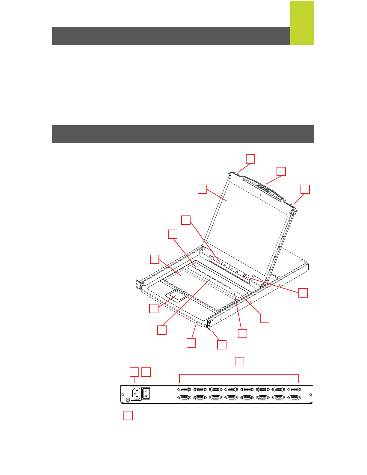
Front View:
1. Handle
2. Slide Release
3. LCD Display
4. LCD Controls
5. Port LEDs
6. Keyboard
7. Touchpad
8. Port Switches
9. Power LED
10. Rack Mounting Brackets
1 1. Lock LEDs
12. Reset Switch
13. Firmware Upgrade Section
Overview
Rear View:
1. Power Socket
2. Power Switch
3. KVM Port Section
4. Grounding T erminal
Note: The GCL1916 is pictured above. The GCL1908 rear panel is the same as the
GCL1916, except that it has 8 KVM ports instead of 16.
1
2
2
3
4
1 2
3
4
5
6
8
13
9
10
11
12
7
Page 3
Side Mountng
Brackets
L Brackets
2
Hardware Installation
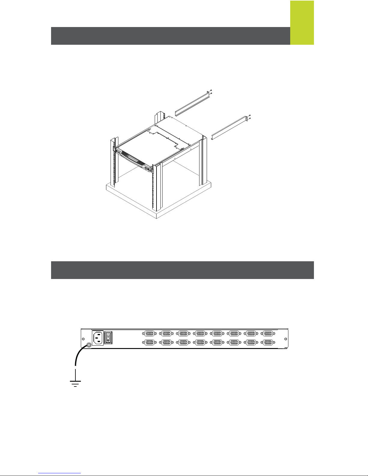
Step 1
While one person positions the switch in the rack and holds it in place, the second person
loosely screws the front brackets to the rack.
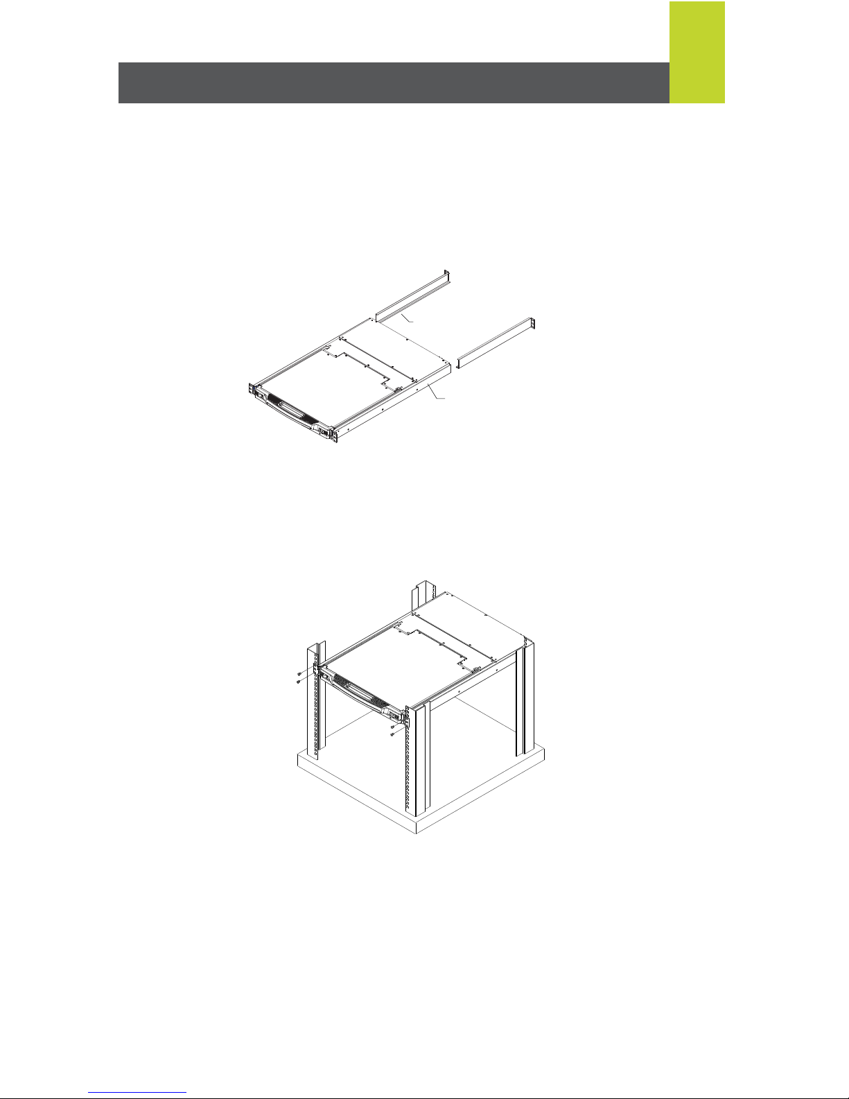
Standard Rack Mounting:
A standard rack mounting kit is provided with your GCL1908 / GCL1916 and can be mounted
in 1U of rack space. The following diagram shows the required components to mount the LCD
KVM to the rack.
Note: It takes two people to mount the switch: one to hold it in place; the other to screw it in.
Page 4
3
Grounding
Use a grounding wire to ground the GCL1908 / GCL1916 by connecting one end of the wire
to the grounding terminal, and the other end of the wire to a suitable grounded object.
Final Step
After the L brackets have been secured, tighten the front bracket screws.
Step 2
While the first person still holds the switch in place, the second person slides the L brackets
into the switch’s side mounting brackets from the rear until the bracket flanges contact the
rack, then screw the L brackets to the rack.
Page 5
4
Open/Close Console
Opening the Console
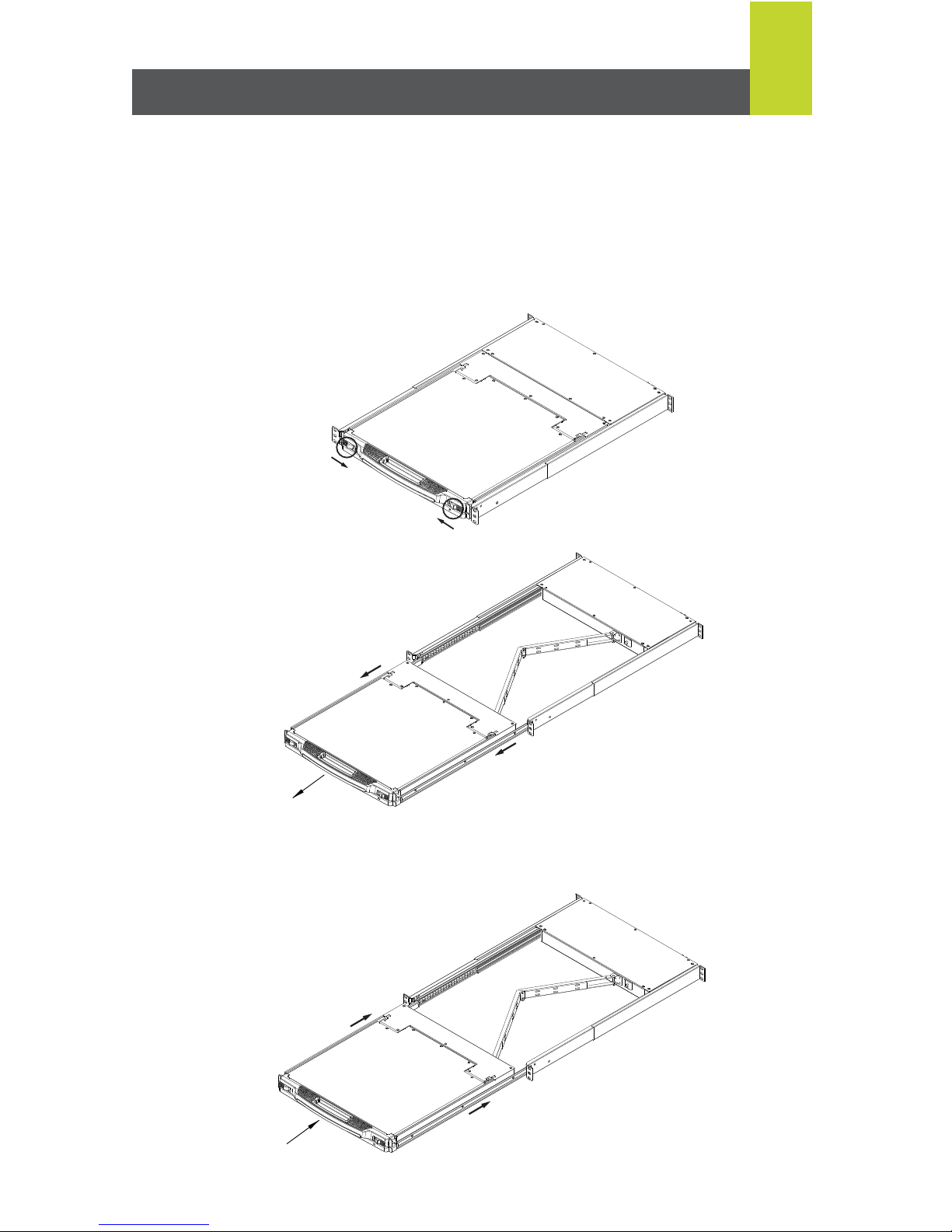
The GCL1908 / GCL1916's console is located under the top cover. To access the console,
slide the console module out and raise the cover.
Note: As a safety precaution, to keep the console from accidentally sliding out, the console is
locked into the In position. Before you can pull the console module out, you must release it by
pushing the catches on the unit's front panel toward the center of the switch.
To slide the console module out, do the following:
1. Push the catches inward
2. Slide the module all the way out.
3. Open the cover.
Closing the Console
To slide the console module back in, do the following:
1. Close the cover.
2. Push the module all the way in until it automatically
locks in place.
Page 6
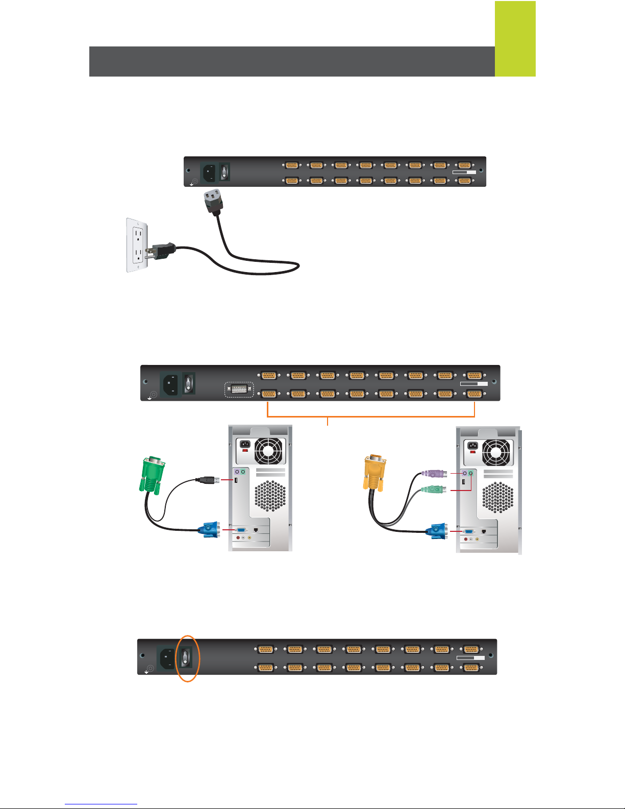
Please make sure the computers are powered off before you start.
Step 1
Connect the power cord to the power outlet and the power socket of the LCD KVM.
Step 3
Turn on LCD KVM by using the power switch that’s located in the back of the LCD KVM.
Final Step
Turn on your computers.
Step2
Connect a USB KVM Cable (with a green connector) or PS/2 KVM Cable (with a yellow
connector) from the KVM switch to each of your computers.
5
Single Level Installation
1
234 5
6
78
9
101112 13
14
1516
PS/2-USB
CPU
PS/2-USB
CPU
or
CONSOLE
1
234 5
6
78
9
101112 13
14
1516
PS/2-USB
CPU
PS/2-USB
CPU
USB KVM Cable
Connection
PS/2 KVM Cable
Connection
1
234 5
6
78
9
101112 13
14
1516
PS/2-USB
CPU
PS/2-USB
CPU
Page 7

Two Level Installation
Trigger OSD
Simply press [Scroll Lock] [Scroll Lock] rapidly .
Note: This hotkey sequence can be changed to [Ctrl] [Ctrl]. Please refer to Hotkey Setting
or
Press the [KVM OSD] Button that is located on the left bottom corner of the built-in keyboard.
OSD Login
By default, the Login and Password are blanks, so simply press [Enter] [Enter] to login. If you
have set a user name and password on the KVM, simply enter them and press enter to login.
OSD Main Screen
When you invoke the OSD, a screen similar to the one below appears:
To control even more computers, up to 8/16 additional switches can be cascaded from
the first GCL1908/GCL1916. As many as 128 (Cascaded with GCS1808) or 256
(Cascaded with GCS1716) computers can be controlled from a single console in a
complete cascade installation.
6
On-screen Display (OSD) Operation
Page 8

OSD Functions
OSD functions are used to configure and control the OSD. For example, you can rapidly switch
to any port, scan selected ports, limit the list you wish to view, designate a port as a quick view
port, create or edit a port name, or make OSD setting adjustments.
On-Screen Display (OSD) Operation
7
Notes:
1. The diagram depicts the administrator’s main screen. The users’ main screen does not show
the F4 and F6 functions, since these are reserved for the administrator and can’t be
accessed by users.
2. The OSD always starts in LIST view, with the highlighted bar at the same position when
OSD was closed last time.
3. Only the ports that have been set accessible by the administrator for the user currently
logged in are visible.
4. The icon next to the monitor icon, indicates that another KVM is attached to the LCD KVM
(Cascading). Click on a switch number , or move the highlight bar to it then press the right
arrow key to expand the list. Similarly, to collapse a switch’s port list, click on the switch
number , or move the highlight bar to it then press the left arrow key to collapse the list.
Page 9
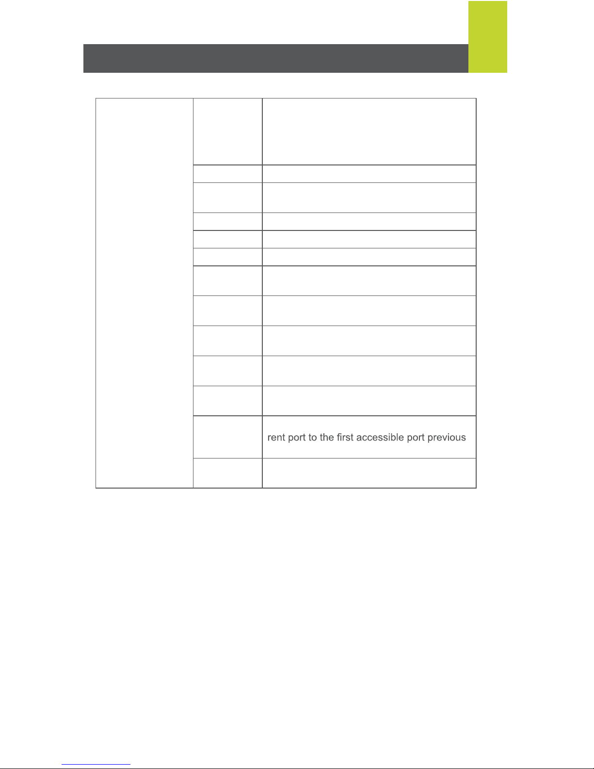
Hotkey Summary Table
8
[Num Lock] + [ - ]
or
[Ctrl] + [F12]
[A] [Enter] or
[Q][Enter]
Invokes Auto Scan mode. When Auto Scan
mode is in effect, [P] or left-click pauses
auto-scanning. When auto-scanning is
paused, pressing any key or another left-
click resumes autoscanning.
[B] Toggles the Beeper On / Off
[Esc] or
[Spacebar]
Exits hotkey mode
[F1] Set Operating System to Windows
®
[F2] Set Operating System to Mac
[F3] Set Operating System to Sun
[F5] Performs a keyboard / mouse reset on the
target computer.
[H] Toggles the Quick Hotkey invocation keys
between [Ctrl]+[F12] and [Num Lock]+[-]
[R] [Enter] This administrator only hotkey restores the
switch’s default values
[PN] [Enter] Switches access to the computer that
corresponds to that port ID
[T] Toggles the OSD Hotkey between [Ctrl] [Ctrl]
and [Scroll Lock] [Scroll Lock]
[←] Invokes Skip Mode and skips from the cur-
to it.
[→] Invokes Skip Mode and skips from the cur-
rent port to the next accessible port
Note:
For completed operation setting method, please download the user
manual from IOGEAR support website.
Page 10

FCC Statement
This product has been tested and found to comply with the limits for a Class A digital device,
pursuant to Part 15 of the FCC Rules. These limits are designed to provide reasonable
protection against harmful interference when the equipment is operated in a commercial
environment. This product generates, uses, and can radiate radio frequency energy. If this
product is not installed and used as directed it may cause harmful interference to radio
communications. Operating this product in a residential area will likely cause harmful
interference which will require correction by the user at his/her personal expense.
CE Compliance
This device has been tested and found to comply with the following European Union
directives: Electromagnetic Capability (2004/108/EC), Low Voltage (2006/95/EC) and
R&TTED (1999/5/EC).
Compliance Information
WE’RE HERE TO HELP YOU!
NEED ASSISTANCE SETTING UP THIS PRODUCT?
Make sure you:
1. Visit www .iogear.com for more product information
2. Visit www .iogear.com/support for live help and product support
Warranty Information
This product carries a 3 Year Limited Warranty. For the terms and conditions of this warranty,
please go to http://www.iogear.com/support/warranty
Register online at http://www.iogear.com/register
Important Product Information
Product Model
Serial Number
Limited Warranty
iogear.custhelp.com
[email protected]
www.iogear.com
19641 Da Vinci, Foothill Ranch, CA 92610
Contact
© 2014 IOGEAR®
 Loading...