

Page 1

Installation Guide
Installation
USB VGA KVM Console Extender
GCE500U
PART NO. M1125-a
Page 2

Page 3

Table of Contents
Package Contents 4
System Requirements 5
Overview 6
Rack Mounting 9
Grounding 11
Standard Installation 12
Advanced Installation 16
Operating Modes 20
LED Indications 21
Federal Communications Commission (FCC) Statement 22
CE Statement 23
SJ/T 11364-2006 24
Limited Warranty 25
Contact 26
3
Page 4

Package Contents
1 x GCE500U Local Unit
1 x GCE500U Remote Unit
1 x USB KVM Cable
2 x Rack Mount Kit
2 x Grounding Cable
2 x Power Adapter
1 x Installation Guide
1 x Warranty Card
4
Page 5

System Requirements
- A Solid CAT5e/6 Cable
Console
- VGA, SVGA, SXGA, UXGA, WUXGA or Multisync monitor
- USB Keyboard and mouse
Computer
- VGA, SVGA, SXGA, UXGA, WUXGA or Multisync video output
- An available USB port
5
Page 6
1
2
4
3
6
5
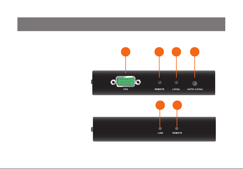
Overview
Front View
CPU Port1.
Remote LED2.
Local LED3.
Operating Mode Pushbutton4.
Link LED5.
Remote LED6.
Local
Remote
6
Page 7
1
2
4
3
5
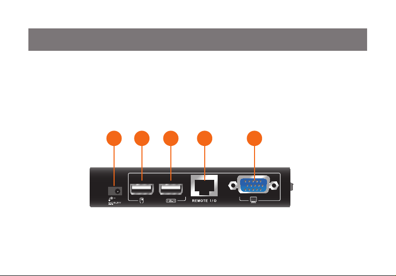
Rear View
Power Jack1.
USB Mouse Port2.
USB Keyboard Port3.
Extension Input/Output Port4.
VGA Monitor Port5.
7
Local & Remote Unit
Page 8
1
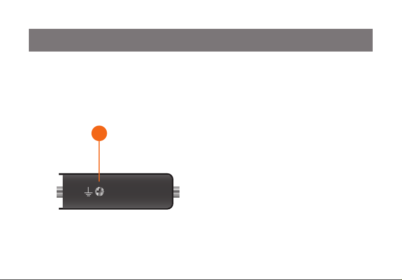
Side View
Grounding Terminal1.
Local & Remote Unit
8
Page 9
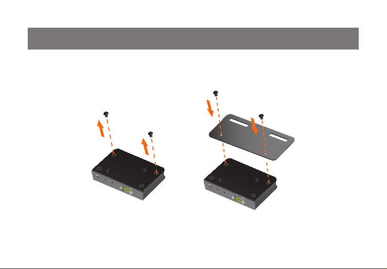
Rack Mounting
Step 1
Unscrew the screws that are in the bottom of the housing, then screw the provided mounting bracket on top
of the units with the screws.
9
Page 10

Step 2
Screw the other side of the bracket onto any available area on the rack.
10
Page 11

Grounding
To prevent damage to your installation, it is important that your devices are properly grounded. Use the provided grounding wires to ground the Local and Remote Unit of the GCE500U. Connect one end of the wire
to the grounding terminal and the other end of the wire to a suitable grounded object.
11
Page 12

Standard Installation
Note: Please make sure your computer is completely shutdown before you begin.
Step 1
Connect the power adapter between the wall outlet and the unit (Both local and remote units)
12
Page 13

Step 2
Connect the provided USB KVM Cable between the local unit’s CPU port and the computer
Local unit
13
Page 14

Step 3
Connect your VGA monitor to the console VGA port, USB keyboard and mouse to the Console USB
keyboard and mouse port respectively (Both local and remote units)
14
Page 15

Step 4
Connect your CAT5e/6 Cable between the Extension Input/Output Ports from the local and remote unit.
Final Step
Turn on your computer and monitors.
15
Page 16

Advanced Installation
Note: Please make sure your computers are completely shutdown before you begin.
Step 1
Connect the power adapter between the wall outlet and the unit (Both local and remote units).
16
Page 17

Step 2
Connect the provided USB KVM Cable between the local unit’s CPU port and the console VGA and
keyboard port of the KVM.
(KVM example: IOGEAR’s GCS1734 )
Step 3
Please refer to the user manual of the specic KVM to complete the KVM installation.
Note: Please ignore the Console VGA, USB Keyboard and mouse ports installation steps from the KVM’s
user manual because you have done this portion from the last step (Step 2).
17
Page 18

Step 4
Connect your VGA monitor to the console VGA port, USB keyboard and mouse to the Console USB
keyboard and mouse port respectively (Both local and remote units).
18
Page 19

Step 5
Connect your CAT5e/6 Cable between the Extension Input/Output Ports from the local and remote unit.
Final Step
Turn on your computers and monitors.
19
Page 20

Operating Modes
Mode Description
Local Only local console has access
Remote Only remote console has access
Note: Remote Mode cannot be selected by the Operating Mode Pushbutton, it only occurs when Auto Mode grants the access to the remote
console.
Auto (Default) Either local or remote console can have access, but only one console
can have access at a time. Whichever console is being used rst will be
granted with the access, for example, if local unit is being used rst, then
it will turn into local mode, but when the local unit becomes idle, it will turn
back into Auto Mode
20
Page 21

LED Indications
LED Status Description
Local LED ON
Remote LED OFF
Local LED OFF
Remote LED ON
Both Local and Remote LED ash Auto Mode
Link LED ON Extension connection is established
Link LED ashes Extension connection is not established
Local Mode
Remote Mode
21
Page 22

Federal Communications Commission (FCC) Statement
This equipment has been tested and found to comply with the limits for a Class B digital device, pursuant
to Part 15 of the FCC Rules. These limits are designed to provide reasonable protection against harmful
interference in a residential setting. This product generates, uses, and can radiate radio frequency energy
and, if not installed and used as directed, it may cause harmful interference to radio communications.
Although this product complies with the limits for a Class B digital device, there is no guarantee that
interference will not occur in a particular installation.
22
Page 23

CE Statement
This device has been tested and found to comply with the requirements set up in the council directive on
the approximation of the law of member states relating to EMC Directive 89/336/EEC, Low Voltage
Directive 73/23/EEC and R&TTE Directive 99/5/EC.
The product has been approved for LVD and covered the following countries:
Belgium, Denmark, France, Germany, Italy, Portugal, U.K., Spain, Sweden
23
Page 24

SJ/T 11364-2006
部件名称
电器部件 ● ○ ○ ○ ○ ○
机构部件 ○ ○ ○ ○ ○ ○
○:表示该有毒有害物质在该部件所有均质材料中的含量均在SJ/T 11363-2006规定的限量要求之下。
●:表示符合欧盟的豁免条款,但该有毒有害物质至少在该部件的某一均质材料中的含量超出
SJ/T 11363-2006的限量要求。
×: 表示该有毒有害物质至少在该部件的某一均质材料中的含量超出SJ/T 11363-2006的限量要求。
有毒有害物质或元素
铅 (Pb) 汞 (Hg) 镉(Cd) 六价 (Cr(VI))
24
多溴联苯
(PBB)
多溴二苯醚
(PBDE)
Page 25

Limited Warranty
IN NO EVENT SHALL THE DIRECT VENDOR’S LIABILITY FOR DIRECT, INDIRECT, SPECIAL,
INCIDENTAL OR CONSEQUENTIAL DAMAGES RESULTING FROM THE USE OF THE PRODUCT, DISK, OR
ITS DOCUMENTATION EXCEED THE PRICE PAID FOR THE PRODUCT.
The direct vendor makes no warranty or representation, expressed, implied, or statutory with respect to the
contents or use of this documentation, and especially disclaims its quality, performance,
merchantability, or tness for any particular purpose.The direct vendor also reserves the right to revise or
update the device or documentation without obligation to notify any individual or entity of such revisions, or
updates. For further inquiries please contact IOGEAR.
25
Page 26

Contact
IOGEAR
19641 Da Vinci
Foothill Ranch, CA 92610
P 949.453.8782
F 949.453.8785
Visit us at: www.iogear.com
26
Page 27

27
Page 28

About Us
About Us
FUN
IOGEAR offers connectivity solutions that are innovative, fun, and stylish,
helping people enjoy daily life using our high technology products.
GREEN
IOGEAR is an environmentally conscious company that emphasizes the
importance of conserving natural resources. The use of our technology solutions
helps reduce electronic waste.
© 2011 IOGEAR
®
 Loading...