

Page 1
GBC232A
RS232 Serial Adapter
QUICK INSTALLATION GUIDE
version 1.1
Page 2
1
Thank you for your purchase of the RS232 Serial Adapter. Featuring Bluetooth
wireless technology, RS232 Serial Adapter creates virtual RS232 connections between
your PCs and other RS232 peripherals. RS232 Serial Adapter is compatible with all
Bluetooth V.2.0-certified and is backward compatible with v1.1/1.2 devices. You can
connect your computers and RS232 devices 100 meters away without cables in your
working environments.
FEATURES
Compatible with Bluetooth v2.0+EDR
Support Bluetooth Serial Port Profile (SPP)
Operate in 2.4GHz~2.483GHz ISM band
Operating distance up to 100 meters
Wide coverage with Class I RF
Three LEDs Indicating
Power On/Off
Configuration/ Data Mode
Bluetooth Link
Easy operation and setup
Support COM port interface: DTE or DCE
Reset function
SYSTEM REQUIREMENTS
PCs can optionally have a Bluetooth device installed, such as a Bluetooth USB dongle. It
allows you to communicate with RS232 Serial Adapter.
Windows Systems: Win 98/Me/2000/XP/XP x64.
BEFORE YOU START
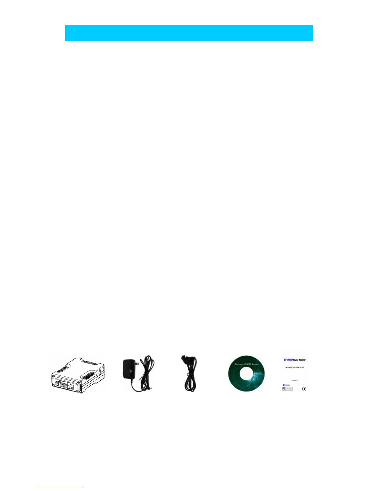
1.Confirm Box Contents
RS232 Serial Adapter Power Adapter RS232 Extension Cable CD QSG
EXTENSION CABLE
A RS232 Extension Cable provides you to connect your RS232 Serial Adapter (DTE/DCE) to
your RS232 device easier. Please refer to Appendix A for its pinout assignments.
WELCOME
Page 3
2
RS232 SERIAL ADAPTER
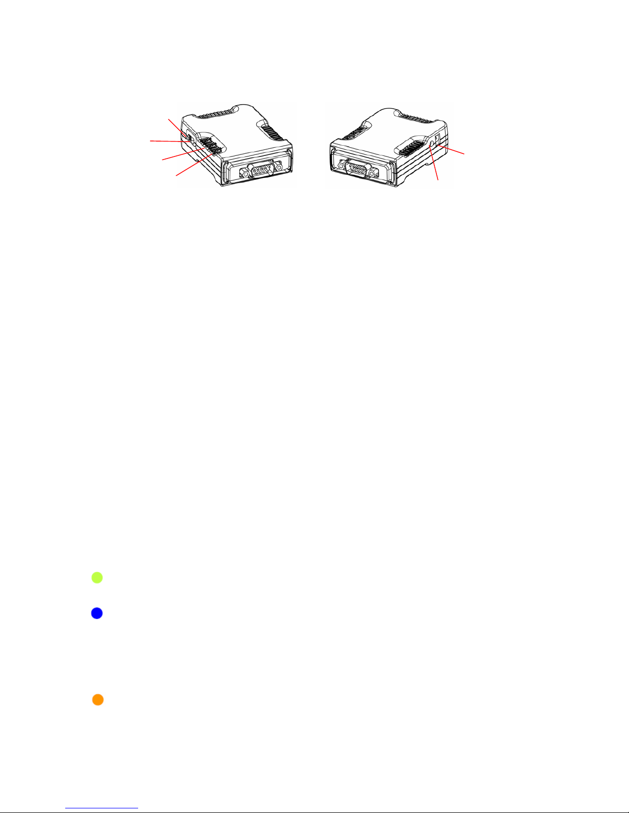
GETTING T O KNOW YOUR RS232 SERIAL ADAPTER
1). RS232 Connector:
DTE - Connect to any DCE device (Master/such as a modem).
DCE - Connect to any DTE device (Slave/such as a PC).
2). Mode Button:
Push it to change operation between Configure/Data Mode and Reset function.
3). Apply power to Bluetooth RS232 Serial Adapter by using the power adapter
accompanied.
4). Set the slide switch position to right (toward 9-pin connector).
(Option: Set it to left position (away from 9-pin connector) features NO DC Power
Adapter is needed. A DC power must be applied to Bluetooth Adapter through pin-9 of
RS232 connector).
5). A one-to-one RS232 Extension Cable allows you to extend the connection if needed.
FUNCTION OF LED
POWER LED
Power LED turns on when POWER is applied to Bluetooth RS232 Serial Adapter.
BLUETOOTH LED
Bluetooth LED is flashing quickly when Bluetooth is paired and linked.
Bluetooth LED is blinking when there is data transmitted/received between two
paired and linked devices.
<Light flashing 1 second and continues with 1 second blackout repeatedly>
MODE LED
MODE LED is ON when RS232 Serial adapter is staying at Configuration mode.
MODE LED is OFF when RS232 Serial adapter is staying at normal DATA mode.
Slide Switch
DC Power Jack
Mode Button
Bluetooth LED
Mode LED
Power LED
Page 4

3
HARDWARE INSTALLATION :
There are two kinds of RS232 devices in the market :
DTE - Data Terminal Equipment (such as a PC).
DCE - Data Communication Equipment (such as a Modem).
Depending on what kind of the RS232 device your RS232 Serial adapter is going to
connect, you can choose appropriate DTE or DCE RS232 Serial adapter to work with it.
At DCE device side :
Connect a DTE RS232 Serial Adapter to the remote DCE RS232 device (such as a Modem).
At DTE device side :
Connect a DCE RS232 Serial Adapter to any DTE device, such as a PC.
Take a remote Modem for example, you can connect it with a DTE RS232 Serial Adapter.
While at PC side, you can either connect a DCE RS232 Serial Adapter to it, or If no DCE
RS232 Serial Adapter is available, you can also connect a Bluetooth USB dongle to your
PC.
SOFTWARE INSTALLATION
Before you use your RS232 Serial Adapter as a Cable Replacement tool, you must
Pair it with another Bluetooth device first. There is a software RS232 Serial Adapter
Utility–Cable Replacement Config Tool.exe which must be run first to configure your
Bluetooth RS232 Serial Adapter.
The utility is to prepare the hardware parameters for pairing, they are :
● Baud Rate
● Stop Bits
● UART Parity
All the Bluetooth RS232 Serial Adapters must be configured first before they can be
used. The purpose of configuration is to pair two Bluetooth devices for an exclusive
connection between them, and pairing is done by utilizing Bluetooth Address and PIN
code.
In this application, we will show you how to transfer files between two PCs by using
Hyper-Terminal program. Each PC has a DCE RS232 Serial Adapter attached, and we still
keep their pairing PIN code to be 0000.
RS232 SERIAL ADAPTER INSTALLATION
CONFIGURING BLUTOOTH SERIAL ADAPTER
Page 5

4
1. Configuring RS232 Serial Adapter on PC 1:
Step 1: Connect a DCE RS232 Serial Adapter to COM1 Port of PC1. Apply power to it.
Step 2: Push Mode Button until the MODE LED lights, then it enters Configuration Mode.
Step 3: Launch RS232 Serial Adapter Utility-
Cable Replacement Config Tool.exe on PC1.
Step 4: Select COM1 Port which RS232 Serial Adapter
is connected.
We assume it is the first time you are
configuring this RS232 Serial Adapter, you
can choose the default Baud Rate: 115200
Press Connect Button.
Step 5: If it connects successfully, the yellow light
appears, if the connection fails, the red light
appears.
While the connection is done, Cable Replacement
Config Tool loads all of the setting from the RS232
Serial Adapter.
Step 6: Select Master, enter Bluetooth MAC
Address of Remote device which will be pairing
and connecting with; input PIN code “0000”.
Click ADVANCE to change UART Baud Rate,
Stop Bits and UART Parity.
Step 7: Select UART Baud Rate, Stop Bits and
UART Parity.
Press OK button
Then press SET button
Page 6

5
2. Configuring Serial Adapter on PC 2:
Step 1: Connect a DCE Serial Adapter to COM1 Port of PC1. Apply power to it.
Step 2: Push Mode Button until the MODE LED lights,
then it enters Configuration Mode.
Step 3: Launch Serial Adapter Utility-
Cable Replacement Config Tool.exe on PC2.
Step 4: Select COM1 Port which Serial Adapter is
connected.
We assume it is the first time you are
configuring this Serial Adapter, you can choose
the default Baud Rate: 115200
Press Connect Button.
Step 5: If it connects successfully, the yellow light
appears, if the connection fails, the red light
appears.
While the connection is done, Cable
Replacement Config Tool loads all of the setting
from the Serial Adapter.
Step 6: Select Slave, enter Bluetooth MAC Address of
Remote device which will be pairing and
connecting with; input PIN code “0000”.
Click ADVANCE to change UART Baud Rate,
Stop Bits and UART Parity.
Step 7: Select UART Baud Rate, Stop Bits and
UART Parity
Press OK button
Then press SET button
RESET function
If you can’t connect successfully with default setting, please press Mode Button for 5
seconds, MODE LED will blink one time, then RESET is done.
Page 7

6
Federal Communication Commission Interference Statement
This equipment has been tested and found to comply with the limits for a Class B digital device,
pursuant to Part 15 of the FCC Rules. These limits are designed to provide reasonable protection
against harmful interference in a residential installation.
This equipment generates, uses and can radiate radio frequency energy and, if not installed and used
in accordance with the instructions, may cause harmful interference to radio communications.
However, there is no guarantee that interference will not occur in a particular installation. If this
equipment does cause harmful interference to radio or television reception, which can be
determined by turning the equipment off and on, the user is encouraged to try to correct the
interference by one of the following measures:
. Reorient or relocate the receiving antenna.
. Increase the separation between the equipment and receiver.
. Connect the equipment into an outlet on a circuit different from that to which the receiver is
connected.
. Consult the dealer or an experienced radio/TV technician for help.
FCC Caution: To assure continued compliance, any changes or modifications not expressly
approved by the party responsible for compliance could void the user's authority to operate this
equipment. (Example - use only shielded interface cables when connecting to computer or
peripheral devices).
FCC Radiation Exposure Statement
Th
is equipment complies with FCC RF radiation exposure limits set forth for an uncontrolled
environment. This equipment should be installed and operated with a minimum distance of 20
centimeters between the radiator and your body.
This transmitter must not be co-located or operating in conjunction with any other antenna or
transmitter.
The antennas used fo
r this transmitter must be installed to provide a separation distance of at
least 20 cm from all persons and must not be co-located or operating in conjunction with any
other antenna or transmitter.
This device complies with Part 15 of the FCC Rules. Operation is subject to the following two
conditions:
(1) This device may not cause harmful interference, and (2) This device must accept any
interference received, including interference that may cause undesired operation.
Contact
IOGEAR
support@iogear.com
www.iogear.com
19641 Da Vinci, Foothill Ranch, CA 92610
 Loading...