

Page 1
Page 2

Basic I/O Product Family
NOTICE:
This document contains two separate users manuals.
The first section should be used for the BIO4, BIO8, and BIO16 products.
The second section should be used for the BIO4AD, BIO8AD, and the BIO16AD
products.
If you find that you have any questions with the setup or installation of any duTec
product please feel free to call us:
Phone: 800-248-1632
or
E-mail: info@dutec.net
Page 3

Page 4

Vol.1 Table of Contents
The Basic I/O ........................................................... 1 - 1
ANALOG INPUTS .............................................. 1 - 2
DIGITAL INPUTS............................................... 1 - 4
DIGITAL OUTPUTS: ............................................ 1 - 5
SYSTEM THROUGHPUT ........................................ 1 - 6
COMMUNICATION PROTOCOL .................................. 1 - 8
Available I/O Modules ............................................ 1 - 9
DIAGNOSTICS ................................................ 1 - 10
PHYSICAL CHARACTERISTICS ................................. 1 - 10
PRODUCT TEST ............................................... 1 - 11
Warranty: ..................................................... 1 - 11
MOUNTING ........................................................... 2 - 1
POWER WIRING ....................................................... 2 - 2
COMMUNICATING WITH THE BASIC I/O ................................. 2 - 3
Multidrop ...................................................... 2 - 4
Repeat......................................................... 2 - 4
RS-422 ........................................................ 2 - 5
RS-485 ........................................................ 2 - 5
RS-485 Programming ............................................. 2 - 6
COMMUNICATION WIRING ............................................. 2 - 7
Network load V.S. Noise suppression ........................................ 2 - 8
Network Bias Resistors ........................................... 2 - 8
RS-422 HOST TO BASIC I/O ...................................... 2 - 9
BASIC I/O TO BASIC I/O RS-422 ................................. 2 - 10
RS-485 Host to BASIC I/O ....................................... 2 - 11
BASIC I/O to BASIC I/O RS-485 (Multidrop only) .................... 2 - 12
BASIC I/O Setup ....................................................... 2 - 13
Analog/ Digital ................................................. 2 - 14
Addresses ..................................................... 2 - 14
Baud Rates .................................................... 2 - 14
Protocol Handshake Types ........................................ 2 - 15
Network Type Switch ............................................ 2 - 16
-i-
Page 5

Vol. 1 Table of Contents
Communication verification............................................... 2 - 18
Hardware error codes .................................................... 2 - 19
Hardware watchdog ..................................................... 2 - 19
Sensor/ Actuator I/O wiring ............................................... 2 - 19
Analog Inputs: ................................................. 2 - 20
Analog Outputs: ................................................ 2 - 22
Digital Inputs: .................................................. 2 - 23
Digital Output Wiring............................................ 2 - 24
-ii-
Page 6

The Basic I/O 1
THE BASIC I/O:
BASIC I/Os are a family of small, industrial grade, remote data acquisition and control
systems which exchange data with a Host computer via a serial communications link.
Controlled by a wide range of software running on a Host computer, Basic I/Os are located
near the sensors and actuators. The serial link eliminates the need for expensive and noise
prone signal wiring between field sensors and actuators, and a central control room.
Each BASIC I/O system consists of one logic board connected to a 4, 8, or 16 position I/O
module mounting rack. This combination is then field configurable to accept either analog or
digital electrically isolated input or output modules which can interface to a wide variety of
sensors and actuators.
BASIC I/O networks can service over 4000 analog and/or digital I/O lines in various
combinations.
User selected serial communications between the Host and the first BASIC I/O can be RS422 or RS-485. These communications links allow the units to operate up to 5000 feet apart.
Baud rates from 300 to 38,400 are available.
The BASIC I/O instruction set core complies 100% with that of the OPTO- 22 Optomux ™
With this ASCII character, speak-only-when-spoken-to protocol, a Host transmits inquiry
requests to the BASIC I/O to determine the status of its various process inputs. Similarly, the
software in the Host computer makes control decisions and transmits instructions to the
BASIC I/O, which in turn, makes the proper changes to its various outputs. Both the Host and
its communications link are essential elements in this data acquisition and process control
scheme.
Software for use with the BASIC I/O system can be obtained from a variety of sources.
Nearly every third party SCADA software vendor has developed a driver which is compatible
with this system. In addition, the communication protocol employed by the BASIC I/O
product is a published ASCII printable standard. This makes developing your own software a
simple matter. duTec also offers a software solution called EASY I/O. With this package,
custom QuickBASIC source code is generated to fit the signals generated to fit the signals
located on the BASIC I/O. Once configured, a simple data acquisition program is
automatically generated. This sample can then be altered to fit the particular needs of the user.
1-1(Vol.1)
.
Page 7

The Basic I/O 1
A notable feature of the BASIC I/O is its ability to gather data and perform ranging and
statistical operations on raw data before it is sent to the Host. The Host can thus spend less
time manipulating data and more time gathering it. The following sections discuss the
different signals the BASIC I/O can handle.
ANALOG INPUTS:
duTec analog input modules are 100% isolated and accept a wide range of voltages, currents,
the outputs of thermocouples, RTDs, and 590 type temperature probes.
BASIC I/O instructions provide linearized thermocouple and RTD sensor data. Engineering
unit conversion is performed by the host software, such as duTec’s EASYIO program
generator.
The BASIC I/O samples individual analog inputs at the constant rate of samples per second.
The effective sample rate per channel is determined by the total number of channels to be
sampled.
Analog input instruction types are:
Input Value Determines signal levels, with 12 bit (1 part in 4096) resolution
Offsets Input values can be software offset or “Zeroed” with 12 bit (1 part in
4096) resolution over the module’s specified range.
Gain/Slope The amplitude of input values can be software multiplied by factors
ranging from 0.25 to 4.0.
Range Limits The occurrence of input values falling out of user defined upper or
lower limits can be flagged.
Minimums The minimum level of input values can be captured.
Maximum The maximum level of input values can be captured.
Averages Can calculate average input amplitude for 1-65,535 samples.
Temperature Provides linear temperature in C for thermocouples, RTD and type
590 temperature probes.
Thermocouple modules provide cold reference junction compensation.
1-2(Vol.1)
Page 8

The Basic I/O 1
ANALOG OUTPUTS:
Analog output modules are 100% isolated. These self-sourcing modules provide the voltage or
current necessary to drive standard instrumentation loads. All are updated every 10 Ms, or 100
times per second.
Analog output instruction types are:
Level Value Can set output levels, as a fraction of the module’s full scale
range, and are specified with 12 bit (1 part in 4096) resolution.
Waveforms Can provide square, triangle, sawtooth or ramp waveforms,
Maximum and Minimum amplitudes, as a fraction of the output
module’s full scale range, are specified with 12 bit (1 part in
4096) resolution. Waveform periods are specified from 0.1 to
6,553 seconds (about 109 minutes).
1-3(Vol.1)
Page 9

The Basic I/O 1
DIGITAL INPUTS:
Digital input modules detect the presence or absence of a field signal. Module types vary from
AC to dry contact sense. Because the industry standard modules are optically isolated, the
response time performance of digital input instructions can be limited by the delay in the input
modules themselves. Some modules can have rise and fall times of up to 40 milliseconds.
Digital input instruction types are:
Read Read the On or Off state of all inputs. This data is
updated every 10 Milliseconds.
Edge Detection Off-to- On and On-to-Off transitions can be detected
within 1 millisecond of their occurrence. Action is
only reported every 10 milliseconds.
Pulse Widths BASIC I/Os can report pulse width measurements
from .01 seconds to 46.6 hours. Minimum resolution
is .01 seconds (Pulse widths up to 10.9 minutes).
Either on or off pulses can be measured.
Pulse Counting Pulses can be counted up to a total of 65,535. To be
reliably counted, pulses must have a minimum On and
Off time of 1 millisecond. Thus the maximum
counting rate for a 50% duty cycle square wave is
once every 2 milliseconds (500Hz).
Frequency Direct frequency measurements can be made on
digital inputs at rates of up to 500 Hz with a user
specified time base of from .01 to 2.55 seconds.
1-4(Vol.1)
Page 10

The Basic I/O 1
DIGITAL OUTPUTS:
Digital output modules, commonly referred to as solid state relays, control external AC or DC
power sources. A dry-contact (mechanical relay) with very low contact resistance is also
available.
Digital output instruction types are:
Set outputs Can set individual or multiple outputs On or Off.
Pulse Generator Can generate 1 to 65,535, 50% duty cycle pulses whose equal
On and Off periods can range from 0.01 to 2.55 seconds.
Resolution can be reduced by a factor of 1-256 on a system
wide basis to increase the maximum pulse width available.
Modifiers:
One Shot Can generate On or Off pulse durations of up to 10.9 minutes
Delayed Can generate delayed On or Off outputs after delaying up to
Square wave Can generate square waves with programmable On and Off
with a resolution of 0.01 seconds. Resolution can be reduced by
a factor of 1-256 on a system wide basis increasing duration up
to 46 hours. Re-triggering is available.
10.9 minutes with a resolution of 0.01 seconds. Resolution can
be reduced by a factor of up 1-256 on a system wide basis
increasing the delay before changing state up to 46.6 hours. Retriggering is available.
periods. On and Off periods have a base range from 0.01
seconds to 10.9 minutes. Resolution can be reduced by a factor
of 1-256 on a system wide basis increasing duration to 46.6
hours
.
1-5(Vol.1)
Page 11
The Basic I/O 1
SYSTEM THROUGHPUT:
Input data throughput is the time from beginning of the first character of an input instruction
to the end of the last character of the response. The processing time of the Host computer will
affect the effective throughput.
Output Execution throughput is the time from the beginning of the first character of an
instruction until the actual output changes. Because the instruction acknowledgment occurs
before the outputs actually change state, the processing time of the host computer controlling
output instructions can reduce the effective throughput. This is even possible at 38,400 baud
to instruct the BASIC I/O to turn a digital output on and then immediately instruct it to turn
back off so quickly that the module never actually gets activated
Tables below show milliseconds per channel and channels per second for 1 and 16 I/O
channel cases
Baud Rate mSec/
300 501 2 501 32 379 3 379 42
600 251 4 251 64 195 5 195 82
1200 126 8 126 127 104 10 104 154
2400 64 16 64 252 58 17 58 277
4800 32 31 32 496 35 29 35 458
9600 17 60 17 962 23 43 23 682
19200 9 113 9 1816 18 56 18 902
38400 5 204 5 3261 15 67 15 1076
Baud Rate mSec/
300 639 2 2639 6 484 1984 2 8
600 323 3 1323 12 250 4 1000 16
1200 164 6 664 24 134 7 509 31
2400 85 12 335 48 75 13 263 61
4800 46 22 71 94 46 22 140 114
9600 26 39 88 181 32 32 78 204
19200 16 63 47 339 24 41 48 335
38400 11 91 27 602 21 48 32 494
.
1 Channel 16 Channels 1 Channel 16 Channels
Input (Digital M) Output (Digital J)
Chan/Sec mSec/
Chan
Input (Analog L) Output (Analog S)
1 Channel 16 Channels 1 Channel 16 Channels
Chan/
Chan
Sec
THROUGHPUT TABLES
Chan/ Sec mSec/
16 Ch
mSec/
Chan/ Sec mSec/
16 Ch
Chan
Chan
.
Chan
/Sec
Chan
/Sec
mSec/
16 Ch
mSec/
16 Ch
Chan /Sec
Chan /Sec
1-6(Vol.1)
Page 12

The Basic I/O 1
It should be noted that the values in the preceding throughput tables and the following
equations reflect only the communications overhead and inherent processing delay of the
BASIC I/O equipment. In practice, a significant amount of overhead will be devoted to other
processing tasks such as screen updates, Data logging, etc... Typically these other tasks
become the limiting factor in the “overall” throughput.
The equations below can be used for determining the hardware’s role in throughput for any
number of channels. (t is in Milliseconds) Throughput for digital I/O is independent of the
number of channels.
Digital Input Data
t digital Input = 1000*((150/Baud Rate) +0.001)
Digital Output Execution
Throughput for analog I/O varies with the number of channels, n.
Analog Input Data
Analog Output Execution
For determining the throughput for systems with a mixture of analog and digital data inputs
and the execution of analog and digital outputs, it is necessary to determine the time for each
instruction using these equations. The sum of these, t, In milliseconds, is the time required to
provide the service required by all instructions.
Dividing this sum into 1000 (milliseconds) yields the number of cycles per second.
(Digital M) Time for 1-16 channels:
(Digital J) Time for 1-16 channels:
t digital Output = 1000 ((110/Baud Rate) +0.012)
(Analog L) Time for n channels:
t analog Input = 1000 *(((150 + 40 * n)/Baud Rate) + 0.006)
(Analog S) Time for n channels:
t analog output = 1000 *(((110 + 30 *n)/Baud Rate) + 0.017)
t=t digital Input + t digital Output + t analog Input + t analog Output
Complete cycles/ Sec = 1000/ t
1-7(Vol.1)
Page 13

The Basic I/O 1
COMMUNICATION PROTOCOL:
The BASIC I/O Communication Protocol is 100% compatible with the Opto-22 Optomux™
protocol. This ASCII printable serial protocol uses a “speak-only-when-spoken-to” format
where only the host can initiate an information exchange. Each BASIC I/O unit installed in a
network has a unique address. This address is embedded in the instruction generated by the
host computer. Every BASIC I/O chassis receives the instruction but only the unit which is
set to the address found in that instruction will respond. Every string of data whose length is
greater than one character is followed by a checksum to ensure data integrity. This protocol
also provides an instruction verification mode for further data transmission reliability.
As a result of the specific nature of the BASIC I/O communications protocol, the RS-422 or
RS-485 network can be shared with other devices whose protocol is similar.
A knowledge of serial communications, hexadecimal to decimal conversion, and string data
manipulation is required to compose custom user generated Host software. DuTec’s EASY
I/O software is designed to minimize these obstacles.
1-8(Vol.1)
Page 14

The Basic I/O 1
ANALOG INPUTS, 12 BIT ANALOG OUTPUTS, 12 BIT
IIF10K-B Input 300Hz -10KHz OV1 Output 0-1V, self-sourcing
Frequency
IF2.5K-L Input 0-2.5KHz OV5 Output 0-5V, self-sourcing
IF5K-l Input 0-5KHz OV10 Output 0-10V, self-sourcing
IF10K-L Input 0-10KHz
IV25M Input 0-25mV OI420 Output 4-20mA, self-sourcing To 275 Ohm
IV50M Input 0-50mV
IV100M Input 0-100mV
IV1 Input 0-1V
IV5 Input 0-5V AC
IV5B Input Bipolar +/-5V IAC5 Input 90-140Vac
IV10 Input 0-10V IAC5A Input 180-280Vac
IV10B Input Bipolar +/-10V DC
IVAC Input 28-140Vac IDC5D Input 3-32Vdc Fast, >500Hz
IVAC-A Input 56-280Vac IDC5S* Input Dry Contact Sense Built-in Isolated
II420 Input 4-20mAdc
IIAC5 Input 0-5Aac
ITCE Type E 0 To 435 C AC
ITCJ Type J 0 To 700 C OAC5 Output 12-140Vac, 3.5A
ITCJ-1 Type J -80 To 750 C OAC5A Output 24-280Vac, N.C.(Normally Closed)
ITCK Type K -100 To 924 C OAC5J Output 20-280Vac, 6.0A
ITCK-1 Type K -110 To 1250 C
ITCR Type R 0 To 960 C DC
ITCR-1 Type R 0 To 1760 C ODC5 Output 5-60Vdc, 3.5A
ITCS Type S 0 To 1034 C ODC5A Output 4-200Vdc, 1.0A
ITCS-1 Type S 0 To 1760 C ODC5R Electro-Mechanical 0.5A Relay Form A,
ITCT Type T -200 To 224 C
I TCT-1 Type T -120 To 400 C
ITCT-2 Type T 0 To 150 C IDC5Z* Input +/-200mV, 0-10KHz Digital**
ITR10 10 Ohm Cu -55 To 150 C
ITR100 100 Ohm Pt -55 To 350 C
ITR100-1 100 Ohm Pt 0 To 100 C Fuses
ITP590 -188.4 To 150 C FM-1 Fuse assembly, 1.0A
ITP590-1 -50.0 To 150 C FM-3 Fuse assembly , 3.0A
Voltage
Voltage
Current
Thermocouple
RTD
Type 590 Temperature Sensor FM-06 Fuse Assembly 0.062A
Available I/O Modules
Current
load.
DIGITAL INPUTS
Voltage Source
IDC5NP Input 10-32 Vdc, 15-32Vac Non-Polarized
DIGITAL OUTPUTS
Normally Open (NO)
SPECIAL PURPOSE
SPS-1* Sensor Power Supply 18-24 Vdc, 30mA
TI01 Digital Input/ Output Test Module with Field
Switch and LED
SUPPORT PRODUCTS
FM-5 Fuse assembly, 5.0A
* When selecting a power supply for the system assume 25mA for standard digital modules and 100 mA
for marked with an *** The IDC5Z module is used for low-level signals and will pass signals at the rate
of 10KHz The BASIC I/O however, is limited to signals up to 500Hz.
1-9(Vol.1)
Page 15
The Basic I/O 1
DIAGNOSTICS:
To confirm internal operations and communications link integrity, a set of built-in diagnostics
test key system functions each time power is applied. Diagnostics reduce both installation
debugging and operation troubleshooting.
A hardware watchdog timer insures safe shutdown in the event of processor or software
failures by turning all outputs OFF. Normally ON modules are available for those loads that
must remain ON.
PHYSICAL CHARACTERISTICS
Power Requirements
Voltage: 5.0-5.4Vdc
Current: 250mA +25mA Per digital module.
Note that the current draw of some specialized digital modules Such as the IDC5S or the
ODC5R, can be substantially larger Than 25mA. Consult the specific module data sheet for
this Value when sizing power supplies.
Operating Temp. 0 C to 60 C Contact factory for other operating temp
Ranges
Humidity 95% non-condensing
Weight 22 oz. Max (BIO16) Not including modules.
BASIC I/Os are ready to install, only dc power, communication and sensor or actuator wiring
is required
1-10(Vol.1)
Page 16

The Basic I/O 1
PRODUCT TEST
Every BASIC I/O is burned-in at 70 °C while operating in a network for a period of 24 hours
prior to shipment.
Every analog I/O module is operated and tested while it’s ambient operating temperature is
cycled over the specified operating range of 0°C to 60°C for a period of 24 hours.
BASIC I/O Models:
BIO4 4 Position BASIC I/O Unit Includes SLB Logic Board and SMB4 Module board
less modules and power supply.
BIO8 8 Position BASIC I/O Unit Includes SLB Logic board and SMB8 module board
less modules and power supply.
BIO16 16 Position BASIC I/O Unit Includes SLB logic board and SMB16 module board
less modules and power supply.
Warranty: duTec warrants its products to be free of defects in materials and
workmanship for a period of two (2) years from date of shipment.
DuTec may, at its option repair or replace all materials found to be
defective. All repair or replacement must be performed by duTec
personnel. Any parts determined by duTec to be defective as a result
of abuse, attempts to repair, or misuse by the customer will be repaired
at the expense of the customer.
1-11(Vol.1)
Page 17

NOTES
The Basic I/O 1
1-12(Vol.1)
Page 18
Setup & Installation 2
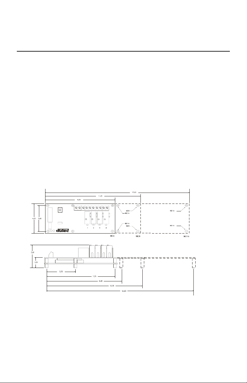
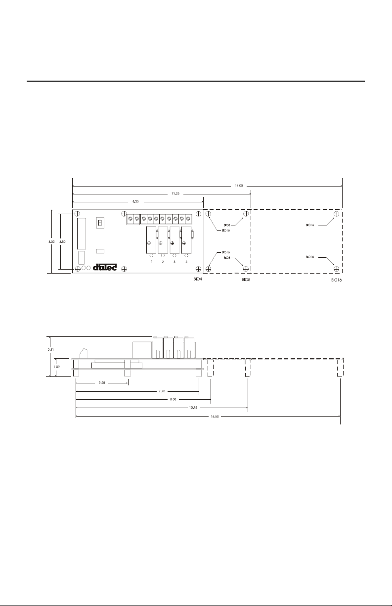
MOUNTING:
BASIC I/Os come in 4, 8, and 16 channel versions. Figure 2-1 below shows the footprint of
each BASIC I/O. Using corner holes, the unit can be mounted with 4- #6 or #8 round head or
pan head screws. The BIO16 version has two additional mounting holes located near the
center of the board as well. Hole locations in relation to the overall dimensions for each are
shown below. Since the same BASIC I/O boards are used for digital or analog applications,
the same mounting dimensions and panel space are used for both.
FIGURE 2-1 BASIC I/O FOOTPRINT
2-1(Vol.1)
Page 19

Setup & Installation 2
POWER WIRING:
Power connections are made at the 2 position terminal block located on the module board
marked +5V and GND No. 8 captive wire clamps accept 10-16 AWG wire or spade lugs.
+5V GND
Power wiring conventions:
+ of the power source to the +5V terminal
- of the power source to the terminal marked GND
Power requirements
Voltage: 5.0- 5.4Vdc
Current: 250 mA + 25mA per digital module or 250 + 200mA per analog
module.
Note that the current draw of some specialized digital
modules such as the IDC5S or the IDC5Z, can be
substantially larger than 25 mA. Consult the specific
module data sheet for this value when sizing power
supplies.
Practices: In general it is good practice to reserve the +5Vdc power supply
exclusively for the task of powering one or more BASIC I/O units. As
with any microprocessor based equipment, reasonably clean power is
required for reliable operation. Sharing power with other devices such
as field signal transducers and contact excitation should be avoided.
2-2(Vol.1)
Page 20

Setup & Installation 2
COMMUNICATING WITH THE BASIC I/O:
The BASIC I/O is designed to serve as an intelligent I/O front end for a Host computer
(Typically a P.C.). The host and BASIC I/O communicate over a serial link. This interchange
is half-duplex in nature; that is to say the host and BASIC I/O will never be transmitting at
the exact same time. Further, the communications protocol is considered “speak-only-whenspoken-to”; the Host must poll the BASIC I/O whenever it needs fresh data. This polling is
accomplished when the host sends an instruction to the BASIC I/O. The BASIC I/O will then
generate a reply. Each valid instruction will illicit a corresponding response. The integrity of
this communication is verified using message content checksums.
The serial communication is a form of ASCII printable characters and makes heavy use of the
hexadecimal numbering system. The format of the ASCII characters used is: One start bit,
eight data bits, one stop bit, and no parity.
2-3(Vol.1)
Page 21
Setup & Installation 2
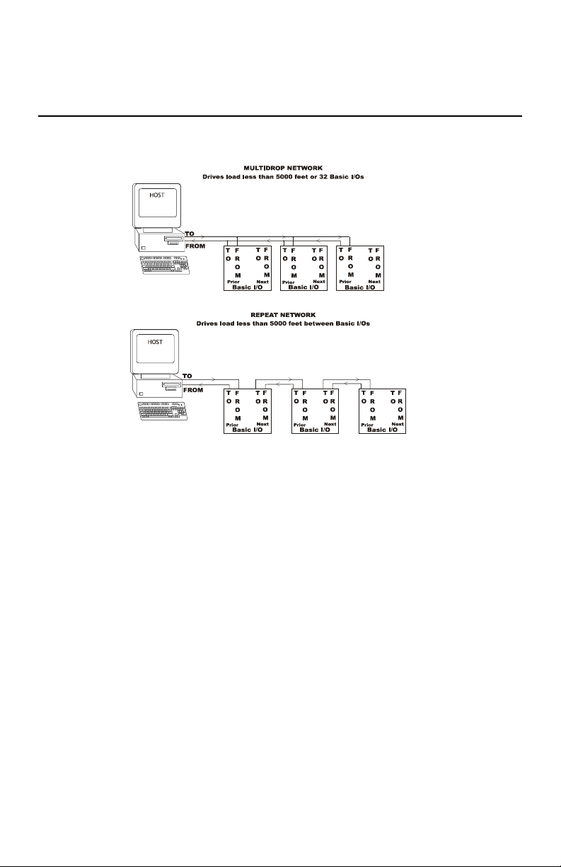
BASIC I/Os can be networked together to obtain up to 4096 I/O points of data. These serial
networks can be either multidrop or repeat.
Figure 2-3 Multidrop V.S. Repeat networks
Multidrop:
Multidrop networks can be up to 5000 ft long end-to-end.
Each station is passively located on the network and represents one “Drop” or
load to the host communication driver.
A multidrop network will tolerate loss of power to any one station without
effecting the rest of the network..
RS-485 can only be multidrop
Signal boost may be necessary depending on line conditions and number of
drops.
Repeat:
Repeat networks can be as long as 5000 ft between each unit.
Each station plays an active role in communications to other units. If power is
removed from a unit in a repeat network, communications to units “downstream”
from it will be lost as well.
2-4(Vol.1)
Page 22

Setup & Installation 2
The serial communications link between a Host computer and a network of BASIC I/Os is
made up of either a single (RS-485 half-duplex) or Dual (RS-422 full duplex) shielded twisted
pair (s) of wires whose shields are connected to a signal common conductor. This
communications link should in turn have an overall shield which is isolated from the signals
(including signal ground) and connected to earth or chassis ground at one location. The most
common cause of difficulty experienced by customers in the field is improperly installed
communications wiring.
RS-422:
Advantages:
Easier to implement in software since host driver need not be controlled.
Can be either Multidrop or Repeat
No turn-around delay required.
Disadvantages:
Requires five conductor wire instead of three
RS-485:
Advantages
Needs only 3 wire conductor
Disadvantages:
:
Host 485 driver control must be implemented requiring tricky serial port manipulations
Can only be Multidrop
Usually requires turn around delay implementation.
2-5(Vol.1)
Page 23

Setup & Installation 2
RS-485 Programming:
The BASIC I/O will work equally well when connected to either RS-422 or RS-485.
However special host programming considerations may be necessary when implementing an
RS-485 network. Unlike RS-422 where both the transmit and Receive signals have their own
differential pair of conductors, RS-485 utilizes only one
conductors is used bidirectionally and handles both transmit and receive signals. In order for
this to be possible, the transmitter for each device on this type of network must be enabled and
disabled whenever a message is to be sent. The transmitter for the BASIC I/O is designed to
handle this control automatically. However, the transmitter control for most popular RS-485
cards that are installed in the Host computer must be controlled by the user program. This
control is not straight forward and may impact the overall system throughput with inherent
delay periods. The following is a typical instruction/ response transaction between a host
computer and a BASIC I/O using RS-485.
1) The Host computer enables its RS-485 transmitter (usually via the RTS line)
2) The Host then sends an instruction to the BASIC I/O in the form of an ASCII printable
string.
3) Once the Host determines that the string has been completely sent, the RS-485
transmitter is disabled.
4) Every BASIC I/O on the network receives the instruction and begin to decode it. That
particular BASIC I/O addressed begins to construct a response.
differential pair. The single pair of
5) Once the carriage return is of the instruction is received, the BASIC I/O begins to
transmit a response.
6) The Host receives the response and takes the appropriate action.
This interaction is heavily dependant on asynchronous timing. Usually, the Host software has
no real means of determining that the instruction has been completely sent. This means that
the program must calculate the
2-6(Vol.1)
Page 24

Setup & Installation 2
approximate time necessary to transmit the entire instruction before the RS-485 driver is
disabled. Since the BASIC I/O can respond very quickly to the instruction, the Host must
disable the driver as soon as possible in order to receive the BASIC I/Os response. RS-485
communications can be tricky at best and should be seriously considered before being
adopted. Third party software users should make sure that the package they have chosen
supports the particular RS-485 communications card to be used.
COMMUNICATION WIRING:
The Host to first BASIC I/O can be RS-422 or RS-485. Most Host computers come
equipped with an RS-232 serial port. A choice must be made to either equip the host with an
RS-422 or RS-485 card or to use an external RS-232 to RS-422/ 485 converter.
For ranges less than 5000 feet, both RS-422 and RS-485 networks can operate in multidrop
mode. For ranges greater than 5000 feet, RS-422 (NOT RS-485) networks can operate in
repeater mode. In this mode, the distance between individual units can be up to 5000 feet. The
trade-off for using the repeat mode is that the powering down of any single unit disables
communications with all units further “downstream” from the host.
A network of BASIC I/O’s must be made up of units which are configured as either all
multidrop or all repeat.
2-7(Vol.1)
Page 25
Setup & Installation 2
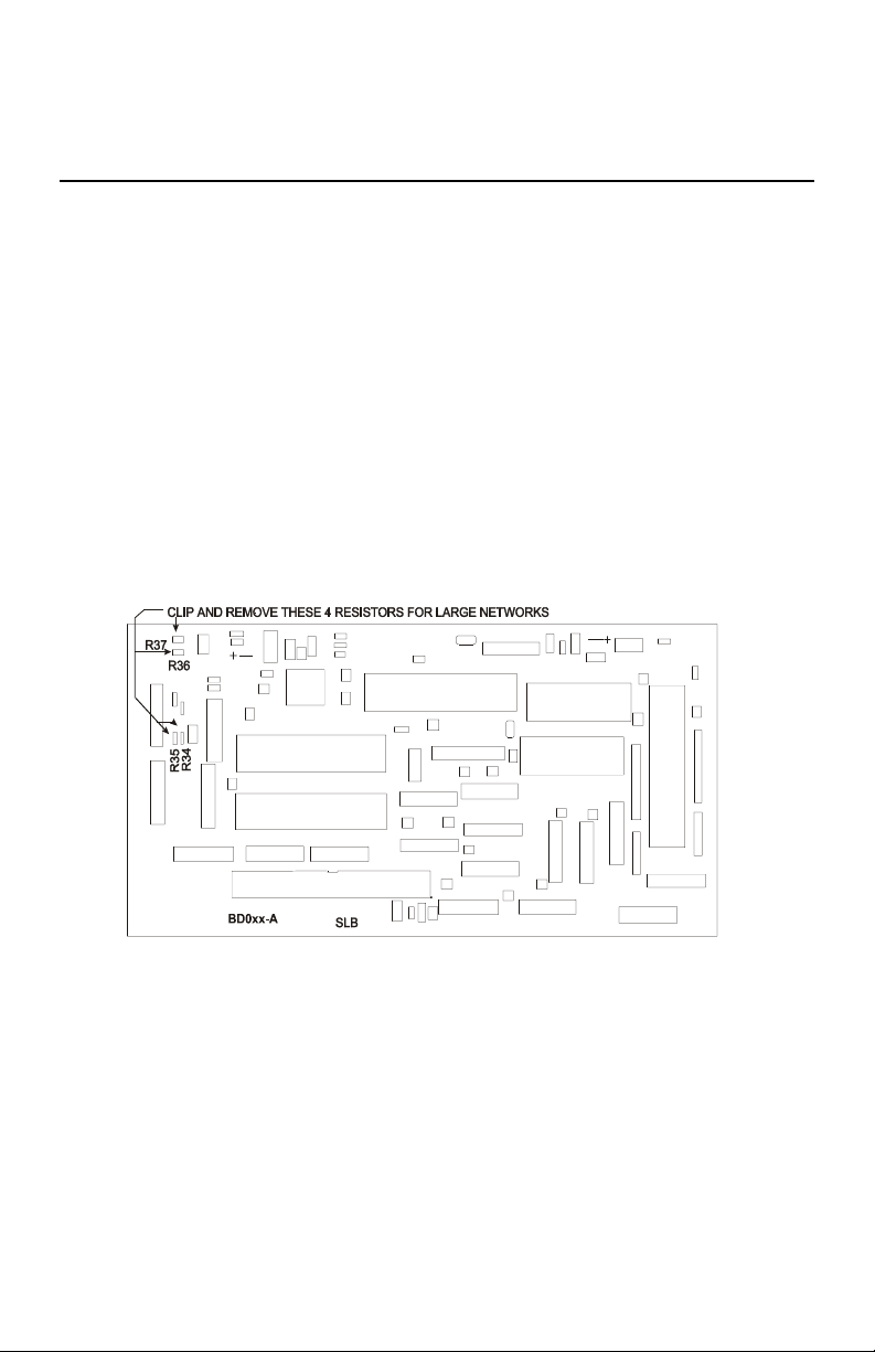
Network load V.S. Noise suppression:
In order to improve RS-485 Bus noise immunity, particularly under tri-state conditions, a pair
of “Network Bias Resistors” have been installed in each BASIC I/O unit. This design feature
has been implemented in order to satisfy the majority of our customers. If it is necessary to
multidrop more than eight BASIC I/O units(but ultimately less than thirty-two devices), It
will be necessary to remove these network bias resistors so as to not exceed the maximum bus
loading. However, in order to retain noise immunity, the network bias resistors should remain
installed in at least one BASIC I/O on the network. Figure 2-4 below shows the location of
the four network bias resistors.
R34 is the 1.5k from prior +bias resistor
R35 is the 1.5k from prior - bias resistor
R36 is the 1.5k from next + bias resistor
R37 is the 1.5k from next - bias resistor
Figure 2-4 Network Bias Resistor Locations
2-8(Vol.1)
Page 26

Setup & Installation 2
RS-422 HOST TO BASIC I/O:
Figure 2-5 RS-422 Host to BASIC I/O wiring
Figure 2-5 shows two individually shielded twisted pairs of AWG 24. Each pair has a ground
wire connected to its shield. These drain wires are then connected to the signal grounds at
each unit. A Separate
tied to earth ground at one location. An example of acceptable wire for this application would
be Belden 8162. In a perfect world with no electrical noise and equal ground potentials
everywhere, the ground connection is not required. However, omitting this signal ground in
industrial applications can lead to costly debugging.
These connections are made by placing a 1/4 inch stripped wire into the openings of the wire
clamp terminal block and tightening the screw. This terminal block will accept gauges from
14 to 30AWG.
An alternate means for network connection is to use the 10 pin male connector located behind
the clamp terminal block. This connector mates with Molex shell number 50-57-9005, and
uses pins number 16-02-0103.
In addition to the Host-To-BASIC I/O wiring, the installer should confirm that the network
type switches are set in the correct position: Multidrop, Repeater, or Last Unit.
shield encases the entire cable. The drain wire for this over-all shield is
2-9(Vol.1)
Page 27

Setup & Installation 2
BASIC I/O TO BASIC I/O RS-422 MULTIDROP OR REPEATER
Figure 2-6 RS-422 BASIC I/O-To-BASIC I/O multidrop
Figure 2-6 shows two individually shielded twisted pairs of AWG24. Each pair has a drain
wire connected to its shield. These drain wires are then connected to the signal grounds at
each unit. A separate
tied to earth ground at one end. An example of acceptable wire for this application would be
Belden 8162. In a perfect world with no electrical noise and equal ground potentials
everywhere, the ground connection is not required. Omitting this signal ground in industrial
applications can lead to unstable operation and costly debugging.
These connections are made by placing a 1/4 inch stripped wire into the openings of the wire
clamp terminal block and tightening the screw. This terminal block will accept gauges from
14 to 30 AWG.
An alternate means of network connection is to use the ten pin male connector located behind
the clamp terminal block. This connector mates with Molex shell number 50-57-9005, and
uses pins 16-02-0103.
In addition to the BASIC I/O to BASIC I/O wiring, the installer should confirm that the
network type switches are set in their correct position: Multidrop, Repeater, or Last unit.
NOTE: The number of BASIC I/Os that can be networked in a multidrop configuration
before a signal amplifier (An external repeater) is needed depends greatly on external factors.
Repeater networks are unlimited.
shield encases the entire cable. The drain wire for the over-all shield is
2-10(Vol.1)
Page 28

Setup & Installation 2
RS-485 Host to BASIC I/O:
Figure 2-7 RS-485 To-BASIC I/O
Figure 2-7 shows one individually shielded twisted pair of AWG 24. Each pair has a drain
wire connected to its shield. These drain wires are then connected to the signal grounds at
each unit. A separate shield encases the entire cable. The drain wire for the over-all shield is
tied to earth ground at one end. An example of acceptable wire for this application would be
Belden 8162. In a perfect world with no electrical noise and equal ground potentials
everywhere, the ground connection is not required. Omitting this signal ground in industrial
applications can lead to unstable operation and costly debugging.
These connections are made by placing a 1/4 inch stripped wire into the openings of the wire
clamp terminal block and tightening the screw. This terminal block will accept gauges from
14 to 30 AWG.
An alternate means of network connection is to use the ten pin male connector located behind
the clamp terminal block. This connector mates with Molex shell number 50-57-9005, and
uses pins 16-02-0103.
In addition to the BASIC I/O to BASIC I/O wiring, the installer should confirm that the
network type switches are set in their correct position: Multidrop, Repeater, or Last unit.
2-11(Vol.1)
Page 29

Setup & Installation 2
BASIC I/O to BASIC I/O RS-485 (Multidrop only):
Figure 2-8 RS-485 BASIC I/O to BASIC I/O Multidrop
Figure 2.8 shows one individually shielded twisted pair of AWG 24. Each pair has a ground
wire connected to its shield. These drain wires are then connected to the signal grounds at
each unit. A Separate
tied to earth ground at one location. An example of acceptable wire for this application would
be Belden 8162. In a perfect world with no electrical noise and equal ground potentials
everywhere, the ground connection is not required. However, omitting this signal ground in
industrial applications can lead to costly debugging.
These connections are made by placing a 1/4 inch stripped wire into the openings of the wire
clamp terminal block and tightening the screw. This terminal block will accept gauges from
14 to 30AWG.
An alternate means for network connection is to use the 10 pin male connector located behind
the clamp terminal block. This connector mates with Molex shell number 50-57-9005, and
uses pins number 16-02-0103.
In addition to the Host-To-BASIC I/O wiring, the installer should confirm that the network
type switches are set in the correct position: Multidrop, Repeater, or Last Unit.
NOTE: The number of BASIC I/Os that can be networked in a multidrop configuration
before a signal amplifier (An external repeater) is needed depends greatly on external factors.
Repeater networks are unlimited.
shield encases the entire cable. The drain wire for this over-all shield is
2-12(Vol.1)
Page 30

Setup & Installation 2
BASIC I/O setup:
BASIC I/O setup is accomplished with a sequential display and pushbutton. Below is a
diagram of the location of these components.:
Figure 2-9 BASIC I/O Connectors, Switches and Indicators.
Unit type (digital or analog), Unit address, baud rate, and 2 or 4 pass protocols are all
pushbutton configurable and appear on the sequential display. After line power application
and the performance of system diagnostics, there is a five second period during which these
setup values any be changed. Changed values are automatically saved on a non-volatile
EEPROM.
2-13(Vol.1)
Page 31

Setup & Installation 2
Analog/ Digital:
The BASIC I/O system must be configured to accept either Analog or Digital I/O modules.
The current I/O type is displayed on the sequential display and is indicated by the character
following the “U”. The unit will display a”1" if the unit is configured as digital and a”2" if the
unit is analog. This value is stored in EEPROM and need only be set once. The factory default
I/O type is digital. Changing the BASIC I/O I/O type is explained after the description of
addresses, baud rates, hand-shaking, and network types.
Addresses:
Each host instruction includes an address made up of two hexadecimal characters (00h to
Ffh). This address determines which chassis is to execute the instruction being sent; all other
chassis are to ignore the instruction. Each BASIC I/O chassis has a unique address. The
factory default address is “00". Changing the BASIC I/O address is explained after the
description of baud rates, hand-shaking, and network types.
Baud Rates:
Any One of the standard baud rates of 300, 600, 1200, 2400, 4800, 9600, 19200, or 38400 can
be used for the serial network communications. The sequential display indicates the letter H
followed by the baud rate divided by 100. BASIC I/Os are shipped at 9600 baud; the
sequential display indicates H096. Changing the BASIC I/O baud rate is explained after the
description of hand-shaking and network types.
2-14(Vol.1)
Page 32

Setup & Installation 2
Protocol Handshake Types:
Two protocol handshake types are available, 2 pass and 4 pass.
2 Pass: The host transmits an instruction to a BASIC I/O.
If the instruction is correctly received (i.e. valid address, instruction type
and correct checksum) the BASIC I/O executes the instruction and
returns the letter “A” and a cr or, where data is to be returned, the letter
“A”, then the data, followed by a two character checksum ending with a
cr.
4 Pass: The host transmits an instruction to a BASIC I/O.
If the instruction is correctly received (i.e. valid address, but not
necessarily the correct instruction type nor checksum), the BASIC I/O
returns an “A” followed by the Echo of the instruction and does not
execute it.
If the host then transmits an E, the instruction is executed in the same
manner as the 2 pass. If the Hos transmits any other character to any unit
on the network, the instruction is disregarded.
The sequential display indicates the letter P followed by 2 or 4. BASIC I/Os are shipped in 2
pass mode; the sequential display indicates P2. The actual setting of the handshake protocol
type is detailed following network type switch.
2-15(Vol.1)
Page 33

Setup & Installation 2
Network Type Switch:
Based upon the selected network configuration, each BASIC I/O must be setup before
communications can begin. This is done with the network switches shown below. The three
basic communication connections for individual BASIC I/Os are:
L1 Repeater
Used in RS-422 networks to extend
range to5000 feet between units
L2 Multidrop
Used in RS-422 or RS-485 networks.
Provides a total network range of 5000
feet.
L3 Last Unit
Must be used in RS-422 and RS-485
networks for the unit most distant from
the host
If there is only one BASIC I/O in a network it is designated L3.
For the network layout, the sequential display indicates the letter “L” followed by “1", “2", or
“3". As shipped, BASIC I/Os are setup as “l3", Last Unit. This parameter is not changed by
push button but is displayed as “l1", “L2", or “L3" after the dip switches have been set and the
unit has undergone a power cycle.
When the unit is configured for “L3" a network termination resistor is placed across the
differential receiver. A value of 150 Ohms was selected to suit most applications. A detailed
analysis of transmission line effects (reflections), which is beyond the scope of this document,
would be necessary to select the ideal termination resistor for any given application.
If the customer wishes to terminate the communication bus externally (at the terminal block
location) then it is imperative that no BASIC I/O network switches be set to “L3".
EIA standards dictate that the total bus impedance for RS-485 can be no less than 60 Ohms.
2-16(Vol.1)
Page 34

Setup & Installation 2
Setup via Pushbutton:
The pushbutton, located on the logic board (see figure 2-9) is used to configure the unit
address, baudrate, and network pass type.
During the diagnostic test period following the application of power, the sequential
display shows “GO GO GO GO GO
appears, places the unit in the setup mode.
The BASIC I/O then flashes: U100
The underlined values represent setup parameters that can be changed.
The digit following the U represents whether the unit is analog/digital
where 1 indicates digital and 2 indicates analog. The initial configuration
is default 1 or digital..
The next two digits indicate the unit address; initially set to address 00h
The three digits after H is the baudrate divided by 100; initially set for
9600 baud.
The 1 digit after P is the handshake protocol type; initially set for 2 pass
The value of each setup character can be changed, as they appear in sequence, by pumping
the pushbutton. As the button is pressed, the display will cycle through the possible values for
each character. When the desired character is displayed simply wait for a brief period for the
display to blank. The next character position to be changed will then appear on the display.
The display continues to cycle through until there is a full cycle with no changes. The BASIC
I/O then stores all values in EEPROM for automatic use following subsequent power cycles.
The unit is now in the operational mode and the sequential display becomes:
/ “ Pumping the pushbutton once while the/
H096 P2
U1
=00 H096 L3 P2
The underlined values represent setup parameters that can be changed
If any desired changes were not completed, line power can be recycled and the setup via
pushbutton can be repeated if necessary.
2-17(Vol.1)
Page 35

Setup & Installation 2
Communication verification:
Network Debugging:
Most startup problems are related to the communication link. The installer is urged, after both
the communications wiring and configuration have been completed, to test the network before
installing I/O modules.
To test the serial communications link, the host transmits the abbreviated test instruction:
>NNA?? For each BASIC I/O address on the network, where NN is the address of each
BASIC I/O. This appears on the Sequential display after the U1 or U2.
Both the Host and the BASIC I/O under test are used to verify wiring, system configuration
and operation. If the addressed unit returns an A, acknowledgment, the communications link
is operational and the selected address is correctly configured. All addresses on the network
should be tested by the same means.
If the A acknowledgment is not returned, the behavior of the two network traffic displays
should be investigated.
The left LED (RECV) should blink on every BASIC I/O when the host transmits an
instruction. This should occur regardless of baud rate. If there is no indication of network
traffic, the failure can be anywhere from the host’s hardware of software to the BASIC I/O.
Generally the failure of the receive light to blink when the host transmits can be attributed to
faulty communications wiring. Locating the cause of the failure should start from the host.
The right LED (marked TRANS) blinks only when the addressed BASIC I/O responds to a
host instruction. If the Trans LED blinks, but the host does not receive an A acknowledgment,
the return circuit is suspect.
If an instruction is sent to the BASIC I/O and the RECV LED flashes but the TRANS LED
does not flash in response, first verify that the Baud rate
are correct, disconnect the wires attached to the “ TO PRIOR + and -” terminals. And resend
the command. If the BASIC I/O Trans LED still does not flash in response to a host request,
contact duTec for service. If the BASIC I/O Trans LED does flash in response to a host
instruction, the return circuit from the BASIC I/O to the host should be verified. If this test is
not successful the host’s receiving hardware should be tested.
2-18(Vol.1)
and Unit address are correct. If both
Page 36

Setup & Installation 2
Hardware error codes:
When the BASIC I/O is initially powered up, it goes through an internal self test. If any of the
self-diagnostics fail, the unit will report an appropriate error code on the sequential display
and halt.
Error Code 3
If a solid 3 appears in the sequential display, recycle power without touching the pushbutton.
This does not mean that there is a problem, it means it is in factory test mode. Recycle power
without holding down the pushbutton.
Other error codes
If 0, 1, 2, 4,6, or 7 appear on the display permanently there is a problem. Recycle power. If
that does not resolve the error condition, please call duTec at 800-248-1632.
Hardware watchdog
The hardware watchdog acts automatically in the event of a hardware or firmware failure and
responds within one second. The hardware watchdog turns all outputs off, and resets the
BASIC I/O. Do not confuse this with the programmable communication watchdog delay
instruction.
Fuses
A plug-in 5 amp, UL rated, fuse is installed between the minus field ierminal and the I/O
module. These fuses are generally only needed to protect output modules. Optional fuse
values are available for special output protection requirements. Fuses are installed in sockets
located on the module board next to the module. Thermocouples and RTD inputs do not
utilize ther terminal block and therefore do not make use of the fuse.
Sensor/ Actuator I/O wiring
Analog or digital modules can be placed at any module position. However it is good practice
for noise pickup, debugging and maintenance reasons to group and wire similar module types
together. For minimum crosstalk between input and output wiring, input modules should be
located at one end followed by output modules.
Modules should NEVER Be installed or removed while power is applied to the BASIC I/O.
Following insertion in their respective sockets, modules should be secured with the captive
screw.
2-19(Vol.1)
Page 37

Setup & Installation 2
Analog Inputs:
Note: analog modules normally run hot to the touch.
Correct polarity connections are essential to proper operation of all the analog inputs.
Connections to terminals marked with a + must be more positive than the terminals marked
with a -. Thermocouples and RTDs are connected directly to modules with special connectors
which insure correct polarity.
Analog input module status indicators are On dimly, when input modules are installed, wired
correctly, and their input signal is within the module’s valid range. If these conditions are not
met, the indicator light may be on brightly, off or may flicker.
The wiring and operation of analog input modules can be verified by the host issuing a
Configure as Input instruction, setup H, followed by a read input value instruction, Analog L.
See the software protocol manual
Figure 2-10, figure 2-11, and figure 2-12 show the wiring for various types of analog inputs.
With the exception of thermocouples and RTD modules, connections are made via the black
terminal strip. In the case of thermocouples and RTDs mating connectors are included. There
must be nothing connected to the screw terminals corresponding to these module positions.
The source of analog input voltage or current is external to the BASIC I/O with the exception
of ITP590, ITR10, ITR100, and ITR100-1.
or quick reference card for instruction details.
Figure 2-10 AC Current and Voltage Wiring.
2-20(Vol.1)
Page 38

Setup & Installation 2
Figure 2-11 Analog Voltage and Current input Wiring
Figure 2-12 Temperature Input Wiring
2-21(Vol.1)
Page 39

Setup & Installation 2
Analog outputs:
Modules should NEVER be installed or removed while power is applied to the BASIC I/O.
Following insertion in their respective sockets, modules should b secured with their captive
screw. Correct polarity is essential to proper operation.
Note: Analog modules run hot to the touch.
Both voltage and current output modules provide their own isolated power output. This
eliminates the need for external power supplies and insures electrical isolation between each
output. This also makes it possible to wire voltage outputs in series to obtain larger voltage
swings.
The wiring of analog output modules can be verified by the host issuing a configure as outputs
instruction, Setup 1, followed by a set output level analog J instruction. See software protocol
manual , or Quick reference card for instruction details.
Module status indicators for analog outputs blink briefly as outputs are updated. It should be
noted that the status indicator only follows the logic instruction to the modules and does not
show that the module or its fuse is present. Outputs can only be verified by observing the
output device or by a multimeter or oscilloscope measurement.
OI420 analog output modules provide the current into loops with total resistance less than 275
ohms. If the loop resistance exceeds 275 ohms, an external power supply must be added to the
loop as shown in figure 2-13 correct polarity is essential. The added voltage should be a
nominal 1 volt for each added 50 ohms of loop resistance in excess of 275 Ohms. The total
added voltage can be up to 5 volts larger than the nominal calculation without damage. The
voltage regulation of the added supply can be as poor as +/-10% without affecting accuracy.
Figure 2-13 Analog Voltage and Current Output Wiring
2-22(Vol.1)
Page 40

Setup & Installation 2
Digital Inputs:
Modules should never be installed while power is applied to the BASIC I/O.
With the exception of IDC5S digital input modules, input sensing current comes from a source
external to the BASIC I/O. IDC5S input modules provide their own current for sensing
contact closures. They can be DESTROYED
The IDC5 and IDC5D input modules are polarity sensitive and operate only when the +
terminal is more positive with respect to the - terminal. Polarity does not affect the
performance of the IAC5, IAC5A, or the IDC5S input modules.
Because the field side of input modules are totally isolated from each other, like polarities can
be wired common to make use of a single power supply.
The wiring and operation of digital input modules can be verified by closing the individual
input sensing contacts and observing the changes on the module status indicators. They are on
when the module circuit is energized. Their wiring can also be verified at the host by issuing a
configure as input instruction, setup H, followed by a read all modules instruction, digital M.
See software protocol manual
, or quick reference card for instruction details.
if an external source is used.
Figure 2-14 Digital Input Wiring
2-23(Vol.1)
Page 41

Setup & Installation 2
Digital Outputs:
Modules should NEVER be installed or removed while power is applied to the BASIC I/O.
The power for ODC5, ODC5A, OAC5, and OAC5A digital output modules comes from a
source external to the BASIC I/O.
Because they contain a protective reverse diode, the ODC5 and ODC5A output modules are
polarity sensitive and operate correctly only when the + terminal is positive with respect to the
- terminal. A DC digital output module connected backwards conducts current through its
protective diode and therefore cannot be controlled.
Polarity does not affect the performance of the OAC5 and OAC5A Digital output modules.
Because the field sides of output modules are totally isolated from each other, like polarities
can be wired common to make use of a single power supply.
The wiring of digital output modules can be verified by the host issuing a configure as output
instruction, control 1, followed by an output on/ off digital J, instruction. See software
protocol manual or quick reference card for instruction details.
The module status indicator should follow the instruction. It should be noted that the status
indicator only follows the logic instruction to the modules and does not show that the module,
its fuse, or that external power is present. Outputs can only be verified by observing the
device or by a multimeter or oscilloscope measurement.
Figure 2-15 Digital Output Wiring
2-24(Vol.1)
Page 42

Vol.1 Index
2 Pass .......................................................... 2 - 15, 2 - 17
4 Pass ................................................................ 2 - 15
Address.......................................................... 1 - 8, 2 - 17
Addresses ............................................................. 2 - 14
ANALOG INPUTS ............................................1 - 2, 1 - 9, 2 - 20
ANALOG OUTPUTS ..........................................1 - 3, 1 - 9, 2 - 22
Analog/ Digital ......................................................... 2 - 14
Analog/digital.......................................................... 2 - 17
BASIC I/O Models...................................................... 1 - 11
Baud rate ............................................................. 2 - 14
Baudrate .............................................................. 2 - 17
COMMUNICATION PROTOCOL .......................................... 1 - 8
Communication verification............................................... 2 - 18
Communications protocol ................................................. 2 - 3
Data throughput ......................................................... 1 - 6
Debugging ............................................................ 2 - 18
DIAGNOSTICS ........................................................ 1 - 10
DIGITAL INPUTS.................................................. 1 - 4, 1 - 9
Digital Outputs ................................................ 1 - 5, 1 - 9, 2 - 24
Error codes ............................................................ 2 - 19
Frequency ............................................................. 1 - 9
Fuses................................................................. 2 - 19
Last Unit.............................................................. 2 - 16
Modules ............................................................... 1 - 9
MOUNTING ........................................................... 2 - 1
Multidrop .................................................... 2 - 4, 2 - 7, 2 - 16
Network ..........................................................2 - 9-2 - 12
Network bias resistors .................................................... 2 - 8
Network Debugging ..................................................... 2 - 18
Network termination resistor .............................................. 2 - 16
Network type switches ...................................... 2 - 10, 2 - 11, 2 - 12
Noise suppression ........................................................ 2 - 8
Power ................................................................. 2 - 2
Power Requirements .................................................... 1 - 10
PRODUCT TEST ....................................................... 1 - 11
PROTOCOL...................................................... 1 - 8, 2 - 15
Repeat................................................................. 2 - 4
Repeater ......................................................... 2 - 7, 2 - 16
RS-422 ........................................................... 2 - 5, 2 - 9
RS-422 .............................................................. 2 - 10
RS-485 ................................................ 2 - 5, 2 - 6, 2 - 11, 2 - 12
Sample rate ............................................................ 1 - 2
Serial communications .................................................... 2 - 5
SYSTEM THROUGHPUT ................................................ 1 - 6
Temperature ....................................................... 1 - 2, 1 - 9
Test.................................................................. 2 - 18
Thermocouple ..................................................... 1 - 2, 1 - 9
THROUGHPUT ......................................................... 1 - 6
Page 43

Page 44

BASIC I/O AD Nov. 24, 2004
Copyright:
Copyright 1995- duTec Inc. All rights reserved. However any part of this
document may be reproduced, provided that DuTec Inc. is cited as the source.
The contents of this manual and the specifications herein may change without
notice.
Trademarks
The DuTec logo, and the BASIC I/O AD are trademarks of DuTec Inc.
Notice to the User
The information contained in this manual is believed to be correct. However
DuTec Inc assumes no responsibility for any of the circuits described herein,
conveys no license under any patent or other right and makes no
representations that the circuits are free from patent infringement. DuTec Inc.
makes no representation or warranty that such applications will be suitable for
the use specified without further testing or modification.
duTec Inc. general policy does not recommend the use of its products in life
support applications where failure or malfunction of a component may directly
threaten life or injury. It is a condition of sale that the user of duTec Inc
products in life support applications assumes all risk of such use and
indemnifies duTec Inc. against all damage.
Warranty
duTec Inc. warrants its products to be free of defects in materials and workmanship
for a period of two (2) years from the shipment date. DuTec Inc. , at its option will
repair or replace all material found to be defective. All repair or replacement must be
performed by duTec Inc. personnel. Any parts determined by duTec Inc.. To be
defective as the result of abuse, attempts to repair, or misuse will be repaired at the
expense of the customer. DuTec Inc. will not be liable for any consequential,
incidental, or special damages.
Page 45

Vol 2 Table of Contents
Overview ..............................................................1 - 1
Capacity .......................................................... 1 - 1
I/O signal compatibility .............................................. 1 - 2
Diagnostics ........................................................ 1 - 2
Communications watchdogs ........................................... 1 - 2
Easy setup......................................................... 1 - 2
Protocol Compatibility ...............................................1 - 3
Available I/O functionality ................................................. 1 - 4
Analog Input Functions .............................................. 1 - 4
Analog outputs ..................................................... 1 - 4
Digital inputs ......................................................1 - 5
Digital outputs .....................................................1 - 5
Extended capabilities ................................................ 1 - 6
Specifications ...........................................................1 - 7
Communications....................................................1 - 7
Power ............................................................1 - 7
Environment .......................................................1 - 7
Ordering Information .....................................................1 - 7
Options ...........................................................1 - 7
Available I/O Modules .................................................... 1 - 8
Installation ............................................................ 2 - 1
Mounting ......................................................... 2 - 1
Power Wiring ...................................................... 2 - 2
Designing the Network.................................................... 2 - 3
Multidrop ......................................................... 2 - 3
Repeat............................................................ 2 - 3
RS-422 ...........................................................2 - 4
RS-485 ...........................................................2 - 4
RS-485 Programming ................................................2 - 5
Communication Wiring ................................................... 2 - 6
Network load V.S. Noise suppression ........................................2 - 7
Network bias resistors ............................................... 2 - 7
Network Type Switches ...................................................2 - 8
Repeat............................................................ 2 - 9
Multidrop ......................................................... 2 - 9
Last Unit .......................................................... 2 - 9
Communications Wiring ................................................. 2 - 10
Host to BASIC I/O AD-RS .......................................... 2 - 10
Page 46

Vol 2 Table of Contents
RS-485 Host to BASIC I/O AD ....................................... 2 - 11
BASIC I/O AD TO BASIC I/O AD RS-422 ............................. 2 - 12
BASIC I/O AD to BASIC I/O AD RS-485 .............................. 2 - 13
Installing the I/O modules ................................................ 2 - 14
Module Wiring ......................................................... 2 - 15
Analog Inputs ..................................................... 2 - 15
Analog outputs .................................................... 2 - 17
Digital Inputs ..................................................... 2 - 18
Digital Outputs ....................................................2 - 19
Chassis Setup ........................................................... 2 - 1
Setup pushbutton ................................................... 3 - 1
Sequential display .................................................. 3 - 1
Baud rate ......................................................... 3 - 3
Protocol Handshake Types ............................................ 3 - 3
Changing Setup Parameters ................................................ 3 - 4
Communication Verification ............................................... 3 - 5
Page 47

Introduction 1
Overview
BASIC I/O ADs are a family of small, industrial grade, remote data acquisition and control
systems which exchange data with a Host computer via a serial communications link.
Controlled by a wide range of software running on a Host computer, BASIC I/O ADs are
located near the sensors and actuators. The serial link eliminates the need for expensive and
noise prone signal wiring between field sensors and actuators, and a central control room.
In applications such as remote process monitoring, factory automation, and energy
management, a variety of signals must be transmitter over long distances. Instead of requiring
expensive, multi-conductor, sensor wiring for each signal, cabling costs can be reduced
significantly by using BASIC I/O ADs and a single communications circuit.
One of the most useful features of the BASIC I/O AD is that in addition to gathering raw
data, it can be instructed to perform many ranging and statistical operations upon the data
before it is given to the host, thus allowing the host to spend less time manipulating data and
more time gathering it. Also the BASIC I/O AD is able to spend more time exposed to the
data which in turn allows it to base its responses to the host on more samples of data. The
BASIC I/O AD may also be directed to manipulate outputs in specific ways to produce
delayed or repetitive effects.
Capacity:
Each BASIC I/O AD system consists of one logic board connected to a 4, 8, or 16 position
I/O module mounting rack. This combination is then field configurable to accept either analog
or digital electrically isolated input or output modules which can interface to a wide variety of
sensors and actuators.
BASIC I/O AD networks can service over 4000 analog and/or digital I/O lines in various
combinations.
Product Test:
Every BASIC I/O AD is burned-in at 70°C while operating in a network for a period of 24
hours prior to shipment.
Every analog I/O module is operated and tested while it’s ambient operating temperature is
cycled over the specified operating range of 0°C to 60°C for a period of 24 hours. A computer
record is generated for every analog I/O module.
1-1(Vol.2)
Page 48

Introduction 1
I/O signal compatibility:
BASIC I/O ADs use duTec I/O modules to match signal requirements exactly. With a direct
interface to sensors, no external signal conditioning is required. Furthermore, all duTec
modules feature total electrical isolation, both module to logic and module to module. Analog
modules are available to measure:
! Millivolts DC to hundreds of volts AC
! Milliamps DC to amps AC
! Frequency to tens of Khz
! Temperature with all popular thermocouples and restive
temperature devices
A full range of industry standard digital modules are available for AC, DC, and dry contact
inputs and outputs to hundreds of volts.
Thermocouple modules provide a cold reference junction compensation. BASIC I/O AD
instructions provide linearized thermocouple and RTD sensor data. Engineering unit
conversions are handled at the host lever.
Diagnostics:
To confirm internal operations and communications link integrity, a set of built-in diagnostics
test key system functions each time power is applied. Diagnostics reduce both installation
debugging and operation troubleshooting.
A hardware watchdog timer insures safe shutdown in the event of processor or software
failures by turning all outputs OFF. Normally ON modules are available for those loads that
must remain ON.
Communications watchdogs:
The BASIC I/O AD can be instructed to implement alarm and fail-safe states in the event of a
communication failure.
Easy setup:
The BASIC I/O AD uses a pushbutton and an on board LED indicator to configure the unit
address, analog VS digital map and baud rate.
1-2(Vol.2)
Page 49

Introduction 1
Protocol Compatibility:
The BASIC I/O AD instruction set core complies 100% with that of the OPTO- 22 Optomux
™ . With this ASCII character, speak-only-when-spoken-to protocol, a Host transmits inquiry
requests to the BASIC I/O AD to determine the status of its various process inputs. Similarly,
the software in the Host computer makes control decisions and transmits instructions to the
BASIC I/O AD, which in turn, makes the proper changes to its various outputs. Both the Host
and its communications link are essential elements in this data acquisition and process control
scheme.
Originally the protocol only allowed for all analog or all digital I/O chassis. Depending on
application requirements, each BASIC I/O AD can respond to pup to three different function
addresses. With their abbreviations they are:
MC Master Unit Control function address
MD Master Unit Digital I/O function address
MA Master Unit Analog I/O function address
It is this multiple function addressing capability of BASIC I/O ADs that allows them to
utilize, without modification, software developed for competitive products. Similarly BASIC
I/O ADs can operate simultaneously on the same network with these products.
1-3(Vol.2)
Page 50

Available I/O functionality:
Introduction 1
Analog Input Functions
Input value Determines signal levels, with 12 bits resolution
1
Offsets Input values can be software offset, with 12 bits resolution,
over the module’s specified range.
Gain/ Slope The amplitude of input values can be software multiplied by
factors ranging from 0.25 to 4.0.
Range Limits The occurrence of input values falling out of user defined upper
or lower limits can be flagged.
Minimums The minimum level of input values can be captured.
Maximums The maximum level of input values can be captured.
Averages Can calculate average input amplitude for 1-65,535 samples.
Temperature Can linearize in, °C, inputs from thermocouples and RTDs.
Will also return temperature probe data.
Analog outputs
Level Value Can set output levels, as a function of the module’s full scale
range, and are specified with 12 bits resolution.
Waveforms can provide square, triangular, sawtooth, or ramp waveforms.
Maximum and minimum amplitudes, as a fraction of the output
module’s full scale range, are specified with 12 bits
resolution. Waveform periods are specified 0.1 to 6,553 Sec
(109 Min). All waveforms are made up of at least ten
segments.
1 One part in 4095
1-4(Vol.2)
Page 51

Introduction 1
Digital inputs
Read Read the on or off of all inputs
Pulse widths The duration of a single or total on/off time of consecutive
pulses can be resolved to the nearest 0.00 seconds for a max
total of 10.9 minutes, or 46.6 hours with multiplied resolution.
Positive or negative edges initiate measurements. The time
scale can be multiplied by a factor of 1-256 on a system wide
basis.
Pulse counting Pulses can be counted up to a total or 65,535. To be reliably
counted, pulses must have minimum on and off times of 1
mSec. Thus the maximum counting rate for a 50% duty cycle
squarewave with equal on and off times for a total of 2 mSec.
Would be 500Hz.
Edge detection Off to on and on to off transitions can be detected within 1
mSec. Of their occurrence. Action is only reported every
10mSec.
Note: The response time performance of digital input instructions can be limited by the
delay in the input modules themselves which can nave on plus off delays of up to 40 mSec.
Digital outputs
Set Outputs Can set individual or multiple outputs on or off Modifiers
One Shot Can generate on or off pulse durations of up to 655.35 seconds
with a resolution of 0.01 seconds. Resolution can be further
multiplied by a factor of 1-256on a system wide basis.
Delayed Can generate on or off pulse durations of up to 655.35 seconds
with a resolution of 0.01 seconds. Resolution can be further
multiplied by a factor of 1-256on a system wide basis.
1-5(Vol.2)
Page 52

Introduction 1
Squarewave Can generate squarewaves with programmable On and Off
periods. On and Off periods have a base range from 0.01 to
2.56 seconds. Resolution can be further multiplied by a factor
of 1-256 on a system wide basis. Re-triggering is available.
Pulse Generator Can generate 1-65,535, 50% duty cycle pulses whose equal on
and off periods can range from 0.01 to 2.55 Sec. Resolution can
be further multiplied by a factor of 1-256 On a system wide
basis.
Extended capabilities:
In addition to operating under the control of a host, Option/L of the BASIC I/O AD has the
ability to perform local control functions without the host. Local control functions (LCFs) can
insure the continued safe operation of closed loop control should the host of its
communication link fail. In addition, LCFs can substantially reduce Host computational load
or communications traffic.
Once characterized, Local Control Function blocks enable the BASIC I/O AD to perform
control tasks without the constant involvement of the host computer. After configuration and
activation via the host instructions, LCFs take data from their input ports, perform
computations and send the results to their outputs where they may drive output modules, or
other BASIC I/O AD internal functions.
Utilizing the LCF’s to perform simple logic tasks such as analog comparisons, summations,
differences, sequence generating or state machine operations eliminates the need for
programmable controllers or special purpose circuitry. This capability allows a more effective
use of the host computer and its communication link because the LCFs handle the operation
of the designated control function. In the meantime the host is only required to monitor
over-all system status and generate the system displays and reports. This is particularly
valuable for systems using modems for communications.
1-6(Vol.2)
Page 53

Introduction 1
Specifications
Network Communications:
duTec supports two standards for transmitting serialized I/O data between the host computer
and the BASIC I/O ADs at baud rates to 38,400.
Maximum Distance
Serial Link Feet Meters
RS-422 /485 5,000 1,524
Physical Characteristics:
Power Supply 5Vdc@<5A
Environment Temperature 0-60 C
Humidity 95% Non-Condensing
Options /L Local Control
Function (LCF)
Ordering Information
Specify duTec products by model number, e.g.,
BIO4AD
BIO8AD
BIO16AD
Options are specified by a series of suffixes to the model number, preceded by a slash for
example:
BIO8AD/L
1-7(Vol.2)
4 Position BASIC I/O AD
8 Position BASIC I/O AD
16 Position BASIC I/O AD
Page 54

Introduction 1
Frequency
I F10K-B Input 300Hz-10KHz OV1 Output 0-1V, self-sourcing
IF2.5K-L Input 0-2.5KHz OV5 Output 0-5V, self-sourcing
IF5K-l Input 0-5KHz OV10 Output 0-10V, self-sourcing
IF10K-L Input 0-10KHz Current
Voltage OI420 Output 4-20mA, self-sourcing To 275
IV25M Input 0-25mV
IV50M Input 0-50mV
IV100M Input 0-100mV AC
IV1 Input 0-1V IAC5 Input 90-140Vac
IV5 Input 0-5V IAC5A Input 180-280Vac
IV5B Input Bipolar +/-5V DC
IV10 Input 0-10V IDC5D Input 3-32Vdc Fast, >500Hz
IV10B Input Bipolar +/-10V IDC5S * Input Dry Contact Sense, Built-in Isolated
IVAC Input 28-140Vac IDC5NP Input 10-32 Vdc, 15-32Vac Non-
IVAC-A Input 56-280Vac
Current
II420 Input 4-20mAdc AC
IIAC5 Input 0-5Aac OAC5 Output 12-140Vac, 3.5A
Thermocouple
ITCE Type E 0 To 435° C OAC5J Output 20-280Vac, 6.0A
ITCJ Type J 0 To 700° C DC
ITCJ-1 Type J -80 To 750 °C ODC5 Output 5-60Vdc, 3.5A
ITCK Type K -100 To 924° C ODC5A Output 4-200Vdc, 1.0A
ITCK-1 Type K -110 To 1250 °C ODC5R Electro-Mechanical 0.5A Relay Form A,
ITCR Type R 0 To 960° C IDC5Z* Input +/-200mV, 0-10KHz Digital**
ITCR-1 Type R 0 To 1760 °C SPS-1* Sensor Power Supply 18-24 Vdc, 30mA
ITCS Type S 0 To 1034° C TI01 Digital Input/ Output Test Module with
ITCS-1 Type S 0 To 1760° C
ITCT Type T -200 To 224 °C
ITCT-1 Type T -120 To 400° C
ITCT-2 Type T 0 To 150 °C
SPECIAL PURPOSE SUPPORT PRODUCTS
RTD
ITR10 10 Ohm Cu -55 To 150 °C FM-06 Fuse assembly, 0.062A 100 mA for
ITR100 100 Ohm Pt -55 To 350 °C FM-1 Fuse assembly, 1.0A
ITR100-1 100 Ohm Pt 0 To 100 C FM-3 Fuse assembly , 3.0A
Type 590 Temperature Sensor FM-5 Fuse assembly, 5.0A
ITP590 -188.4 To 150 °C
ITP590-1 -50.0 To 150 °C
* When selecting a power supply for the system assume 25mA for standard digital modules and 100mA for modules
marked with an *
** The IDC5Z module is used for low-level signals and will pass signals at the rate of 10kHz
however, is limited by communications baudrate.
ANALOG INPUTS, 12 BIT ANALOG OUTPUTS, 12 BIT
Fuses
Available I/O Modules
Voltage
Ohm load
DIGITAL INPUTS
Voltage Source
Polarized.
DIGITAL OUTPUTS
OAC5A Output 24-280Vac, N.C.(Normally Closed)
Normally )
Field Switch and LED
modules marked with an *
The BASIC I/O AD
1-8(Vol.2)
Page 55

Installation 2
Installation
Mounting:
BASIC I/O ADs come in 4, 8, and 16 channel versions. Figure 2-1 below shows the footprint
of each Basic I/OAD. Using corner holes, the unit can be mounted with 4- #6 or #8 round
head or pan head screws. The BIO16 version has two additional mounting holes located near
the center of the board as well. Hole locations in relation to the overall dimensions for each
are shown below.
Figure 2-1 BASIC I/O AD Footprint
2-1(Vol.2)
Page 56

Installation 2
Power Wiring:
Power connections are made at the 2 position terminal block located on the module board
marked +5V and GND No. 8 captive wire clamps accept 10-16 AWG wire or spade lugs.
Power wiring conventions:
+ of the power source to the terminal marked +5V
- of the power source to the terminal marked GND
Power requirements
Voltage: 5.0- 5.4Vdc
Current: 250 mA + 25mA per digital module and 200mA per analog module.
Practices: In general it is good practice to reserve the +5Vdc power supply
exclusively for the task of powering one or more BASIC I/O ADs. As
with any microprocessor based equipment, reasonably clean power is
required for reliable operation. Sharing power with other devices such as
field signal transducers and contact excitation should be avoided
2-2(Vol.2)
Page 57

Installation 2
Designing the Network
In order for the BASIC I/O AD to share its data with the host computer, it must be linked via
a serial connection. This link can be hard-wired using an RS-422 dual twisted pair or an RS485 single twisted pair connection where the wire run between devices is less than 5000 feet.
In any event, the appropriate transmitter of the BASIC I/O AD will be connected to a suitable
receiver of the host computer. Multiple BASIC I/O AD chassis can be networked together to
service large numbers of I/O points. These serial connections can be either multidrop or
repeat.
Multidrop:
Multidrop networks can be up to 5000 ft long end-to-end.
Each station is passively located on the network and represents one “Drop” or
load to the host communication driver.
A multidrop network will tolerate loss of power to any one station without
effecting the rest of the network.
RS-485 can only be multidrop
Signal boost may be necessary depending on line conditions and number of
drops.
Repeat:
Repeat networks can be as long as 5000 ft between each unit.
Each station plays an active role in communications to other units. If power is
removed from a unit in a repeat network, communications to units “downstream”
from it will be lost as well.
2-3(Vol.2)
Page 58

RS-422:
Installation 2
Advantages:
No turn-around delay required.
Disadvantages:
RS-485:
Advantages:
Disadvantages:
Easier to implement in software since host driver need not be controlled.
Can be either Multidrop or Repeat.
Requires five conductor wire instead of three.
Needs only 3 wire conductor.
Host 485 driver control must be implemented requiring tricky serial port
manipulations.
Can only be Multidrop.
Usually requires turn around delay implementation.
2-4(Vol.2)
Page 59

Installation 2
RS-485 Programming:
The BASIC I/O AD will work equally well when connected as RS-422 or RS-485. However
special host programming considerations may be necessary when implementing an RS-485
network. Unlike RS-422 where both the transmit and Receive signals have their own
differential pair of conductors, RS-485 utilizes only one
conductors is used bidirectionally and handles both transmit and receive signals. In order for
this to be possible, the transmitter for each device on this type of network must be enabled
and disabled whenever a message is to be sent. The transmitter for the BASIC I/O AD is
designed to handle this control automatically, the transmitter control for most popular RS-485
cards that are installed in the Host computer must be controlled by the user program. This
control is not straight forward and may impact the overall system throughput with inherent
delay periods. The following is a typical instruction/ response transaction between a host
computer and a BASIC I/O AD using RS-485.
1) The Host computer enables its RS-485 transmitter (usually via the RTS line)
2) The Host then sends an instruction to the BASIC I/O AD in the form of an ASCII
printable string.
3) Once the Host determines that the string has been completely sent, the RS-485
transmitter is disabled.
4) Every BASIC I/O AD on the network receives the instruction and begin to decode
it. That particular BASIC I/O AD addressed begins to construct a response.
5) Once the carriage return is of the instruction is received, then begins to transmit a
response.
differential pair. The single pair of
6) The Host receives the response and takes the appropriate action.
2-5(Vol.2)
Page 60

Installation 2
This interaction is heavily dependant on asynchronous timing. Usually, the Host software has
no real means of determining that the instruction has been completely sent. This means that
the program must calculate the approximate time necessary to transmit the entire instruction
before the RS-485 driver is disabled. Since the BASIC I/O AD can respond very quickly to
the instruction, the Host must disable the driver as soon as possible in order to receive the
BASIC I/O ADs response. RS-485 communications can be tricky at best and should be
seriously considered before being adopted. Third party software users should make sure that
the package they have chosen supports the particular RS-485 communications card to be used.
Communication Wiring:
The Host to first BASIC I/O AD can be RS-422 or RS-485. Most Host computers come
equipped with an RS-232 serial port. A choice must be made to either equip the host with an
RS-422 or RS-485 card or to use an external RS-232 to RS-422/ 485 converter such as the
duTec BaudMASTER.
For ranges less than 5000 feet, both RS-422 and RS-485 networks can operate in multidrop
mode. For ranges greater than 5000 feet, RS-422 (NOT RS-485) networks can operate in
repeater mode. In this mode, the distance between individual units can be up to 5000 feet. The
trade-off for using the repeat mode is that the powering down of any single unit disables
communications with all units further “downstream” from the host.
A network of BASIC I/O AD must be made up of units which are configured as either all
multidrop or all repeat.
2-6(Vol.2)
Page 61

Installation 2
Network load V.S. Noise suppression:
In order to improve RS-485 Bus noise immunity, particularly under tri-state conditions, a pair
of “Network Bias Resistors” have been installed in each BASIC I/O AD unit. This design
feature has been implemented in order to satisfy the majority of our customers. If it is
necessary to multidrop more than eight BASIC I/O AD units(but ultimately less than thirtytwo devices), It will be necessary to remove these network bias resistors so as to not exceed
the maximum bus loading. However, in order to retain noise immunity, the network bias
resistors should remain installed in at least one BASIC I/O AD on the network. Figure 2-4
below shows the location of the four network bias resistors.
R34 is the 1.5k from prior +bias resistor
R35 is the 1.5k from prior - bias resistor
R36 is the 1.5k from next + bias resistor
R37 is the 1.5k from next - bias resistor
Figure 2-2 Network Bias resistor locations
2-7(Vol.2)
Page 62

Installation 2
Network Type Switches
Based upon the selected network configuration, each BASIC I/O AD must be setup before
communications can begin. This is done with the network switches shown in figure 2-3.
Figure 2-3 BASIC I/O AD Connectors, Switches and Indicators.
2-8(Vol.2)
Page 63

Installation 2
The three basic communication connections for individual BASIC I/O ADs are:
Repeat
Used in RS-422 networks to extend range
to 5000 feet between units. Sequential
Display reads L1
Multidrop
Used in RS-422 or RS-485 networks.
Provides a total network range of 5000 feet.
Display reads L2
Last Unit
Must be used in RS-422 and RS-485
networks for the unit most distant from the
host. Sequential display reads L3
If there is only one BASIC I/O AD in a network it is designated L3.
For the network layout, the sequential display indicates the letter “L” followed by “1", “2", or
“3". As shipped, BASIC I/O ADs are setup as “l3", Last Unit. This parameter is not changed
by push button but is displayed as “l1", “L2", or “L3" after the dip switches have been set and
the unit has undergone a power cycle.
2-9(Vol.2)
Page 64

Host to BASIC I/O AD-RS-422:
Figure 2-7 RS-422 Host to BASIC I/O AD
Installation 2
Communications Wiring
Figure 2-7 shows two individually shielded twisted pairs of AWG 24. Each pair has a ground
wire connected to its shield. These drain wires are then connected to the signal grounds at
each unit. A Separate
tied to earth ground at one location. An example of acceptable wire for this application would
be Belden 8162. In a perfect world with no electrical noise and equal ground potentials
everywhere, the ground connection is not required. However, omitting this signal ground in
industrial applications can lead to costly debugging.
These connections are made by placing a 1/4 inch stripped wire into the openings of the wire
clamp terminal block and tightening the screw. This terminal block will accept gauges from
14 to 30AWG. An alternate means for network connection is to use the 10 pin male connector
located behind the clamp terminal block. This connector mates with Molex shell number 5057-9005, and uses pins number 16-02-0103.
In addition to the Host-To-BASIC I/O AD wiring, the installer should confirm that the
network type switches are set in the correct position: Multidrop, Repeater, or Last Unit.
shield encases the entire cable. The drain wire for this over-all shield is
2-10(Vol.2)
Page 65

Installation 2
RS-485 Host to BASIC I/O AD:
Figure 2-8 RS-485 To-BASIC I/O AD
Figure 2-8 shows two individually shielded twisted pairs of AWG24. Each pair has a drain
wire connected to its shield. These drain wires are then connected to the signal grounds at
each unit. A separate
tied to earth ground at one end. An example of acceptable wire for this application would be
Belden 8162. In a perfect world with no electrical noise and equal ground potentials
everywhere, the ground connection is not required. Omitting this signal ground in industrial
applications can lead to unstable operation and costly debugging.
shield encases the entire cable. The drain wire for the over-all shield is
These connections are made by placing a 1/4 inch stripped wire into the openings of the wire
clamp terminal block and tightening the screw. This terminal block will accept gauges from
14 to 30 AWGAn alternate means of network connection is to use the ten pin male connector
located behind the clamp terminal block.
In addition to the Host to BASIC I/O AD wiring, the installer should confirm that the
network type switches are set in their correct position: Multidrop, Repeater, or Last unit.
2-11(Vol.2)
Page 66

BASIC I/O AD TO BASIC I/O AD RS-422
Figure 2-6 RS-422 BASIC I/O AD-To-BASIC I/O AD
Installation 2
Figure 2-6 shows one individually shielded twisted pair of AWG 24. Each pair has a drain
wire connected to its shield. These drain wires are then connected to the signal grounds at
each unit. A separate
tied to earth ground at one end. An example of acceptable wire for this application would be
Belden 8162. In a perfect world with no electrical noise and equal ground potentials
everywhere, the ground connection is not required. Omitting this signal ground in industrial
applications can lead to unstable operation and costly debugging
These connections are made by placing a 1/4 inch stripped wire into the openings of the wire
clamp terminal block and tightening the screw. This terminal block will accept gauges from
14 to 30 AWG. An alternate means of network connection is to use the ten pin male connector
located behind the clamp terminal block. This connector mates with Molex shell number 5057-9005, and uses pins 16-02-0103.
In addition to the BASIC I/O AD to BASIC I/O AD wiring, the installer should confirm that
the network type switches are set in their correct position: Multidrop, Repeater, or Last unit.
shield encases the entire cable. The drain wire for the over-all shield is
2-12(Vol.2)
Page 67

BASIC I/O AD to BASIC I/O AD RS-485
Figure 2-8 RS-485 BASIC I/O AD to BASIC I/O AD
Installation 2
Figure 2.8 shows one individually shielded twisted pair of AWG 24. Each pair has a ground
wire connected to its shield. These drain wires are then connected to the signal grounds at
each unit. A Separate
tied to earth ground at one location. An example of acceptable wire for this application would
be Belden 8162. In a perfect world with no electrical noise and equal ground potentials
everywhere, the ground connection is not required. However, omitting this signal ground in
industrial applications can lead to costly debugging.
These connections are made by placing a 1/4 inch stripped wire into the openings of the wire
clamp terminal block and tightening the screw. This terminal block will accept gauges from
14 to 30AWG
An alternate means for network connection is to use the 10 pin male connector located behind
the clamp terminal block. This connector mates with Molex shell number 50-57-9005, and
uses pins number 16-02-0103.
In addition to the BASIC I/O-To-BASIC I/O AD wiring, the installer should confirm that the
network type switches are set in the correct position: Multidrop, Repeater, or Last Unit.
shield encases the entire cable. The drain wire for this over-all shield is
2-13(Vol.2)
Page 68

Installation 2
Installing the I/O modules:
Certain guidelines must be followed when installing I/O modules on the BASIC I/O AD
Chassis. In particular the analog modules must be grouped separately from the digital
modules on each I/O chassis. Using the worksheets found on the next page, place the desired
I/O modules in the indicated positions.
BASIC I/O AD Module Placement Worksheet
Module# Analog/Digital Module PN Remarks
1
2
3
4
5
6
7
8
9
10
11
12
13
14
15
1)Install all analog input
skip this step.
2) Install Analog output
are used, skip this step.
3) Repeat step 2 for the digital input
modules beginning with module 0 the 1 and so on. If none are used,
modules beginning with the next available module position. If none
and digital output modules
2-14(Vol.2)
Page 69

Installation 2
Module Wiring
Analog Inputs:
Modules should NEVER Be installed or removed while power is applied to the BASIC I/O
AD. Following insertion in their respective sockets, modules should be secured with the
captive screw.
Note: Analog Modules Normally Run hot to the touch
Correct polarity connections are essential to proper operation of all the analog inputs.
Connections to terminals marked with a + must be more positive than the terminals marked
with a -. Thermocouples and RTDs are connected directly to modules with special connectors
which insure correct polarity.
Analog input module status indicators are On dimly, when input modules are installed, wired
correctly, and their input signal is within the module’s valid range. If these conditions are not
met, the in the touchght may be on brightly, off or may flicker.
Figure 2-11, figure 2-12, and figure 2-13 show the wiring for various types of analog inputs.
With the exception of thermocouples and RTD modules, connections are made via the black
terminal strip. In the case of thermocouples and RTDs mating connectors are included. There
must be nothing connected to the screw terminals corresponding to these module positions.
The source of analog input voltage or current is external to the BASIC I/O AD with the
exception of ITP590, ITR10, ITR100, and ITR100-1.
Figure 2-11 AC current and voltage wiring
2-15(Vol.2)
Page 70

Installation 2
Figure 2-12 Analog Voltage, frequency and Current input Wiring
Figure 2-13 Temperature Input Wiring
2-16(Vol.2)
Page 71

Installation 2
Analog outputs:
Modules should NEVER be installed or removed while power is applied to the BASIC I/O
AD.
Note: Analog modules run hot to the touch.
Both voltage and current output modules provide their own isolated power output. This
eliminates the need for external power supplies and insures electrical isolation between each
output. This also makes it possible to wire voltage outputs in series to obtain larger voltage
swings.
Module status indicators for analog outputs blink briefly as outputs are updated. It should be
noted that the status indicator only follows the logic instruction to the modules and does not
indicate the output status. Outputs can only be verified by observing the output device or by a
multimeter or oscilloscope measurement.
Figure 2-14 Analog Voltage and Current Output Wiring
OI420 analog output modules provide the current into loops with total resistance less than 275
ohms. If the loop resistance exceeds 275 ohms, an external power supply must be added to the
loop as shown in figure 2-13 correct polarity is essential.
2-17(Vol.2)
Page 72

Installation 2
Digital Inputs:
Modules should never be installed while power is applied to the BASIC I/O AD.
With the exception of IDC5S digital input modules, input sensing current fomes from a source
external to the BASIC I/O AD. IDC5S input modules provide their own current for sensing
contact closures. They can be DESTROYED
The IDC5 and IDC5D input modules are polarity sensitive and operate only when the +
terminal is more positive with respect to the - terminal. Polarity does not affect the
performance of the IAC5, IAC5A, or the IDC5S input modules.
Because the field side of input modulles are totally isolated from each other, like polarities
can be wired common to make use of a single power supply.
The wiring and operation of digital input modules can be verified by closing the individual
input sensing contacts and observing the changes on the module status indicators. They are on
when the module circuit is energized.
if an external source is used.
Figure 2-15 Digital Input Wiring
2-18(Vol.2)
Page 73

Installation 2
Digital Outputs:
Modules should NEVER be installed or removed while power is applied to the BASIC I/O
AD.
The power for ODC5, ODC5A, OAC5, and OAC5A digital output modules comes from a
source external to the BASIC I/O AD.
Because they contain a protective reverse diode, the ODC5 and ODC5A output modules are
polarity sensitive and operate correctly only when the + terminal is positive with respect to
the - terminal. A DC digital output module connected backwards conducts current through its
protective diode and therefore cannot be controlled. Polarity does not affect the performance
of the OAC5 and OAC5A Digital output modules.
Because the field sides of output modules are totally isolated from each other, like polarities
can be wired common to make use of a single power supply.
The module status indicator should follow the instruction. It should be noted that the status
indicator only follows the logic instruction to the modules and does not show that the module,
its fuse, or that external power is present. Outputs can only be verified by observing the
device or by a multimeter or oscilloscope measurement.
Figure 2-16 Digital output wiring
2-19(Vol.2)
Page 74

Setup 3
Chassis Setup
Figure 3-17 Connectors, Switches, and Indicators
During the setup phase of a BASIC I/O AD system, the chassis is given specific values for
unit address, analog/ digital separator, network baud rate, and protocol pass type. A
momentary pushbutton and seven segment display provide access to these parameters. Figure
3-17 shows the location of these components labeled setup pushbutton and sequential display.
Function addresses:
Each host instruction includes an address made up of two hexadecimal characters (00h-FFh).
At any BASIC I/O AD network connection 3 different types of functions can be performed,
each with its own unique system -wide function address. There are two BASIC I/O AD
addressing modes, offset and variable.
Offset Mode
Units are shipped in the offset mode where only master init control address needs be set (with
a range of 00h-3Fh). The remaining function addresses are automatically calculated and set
based on master address.
3-1(Vol.2)
Page 75

Setup 3
Function Abbrev. Function
Address
Master Unit Control MC 00h (0) UO=00
Master Unit Digital I/O MD 40h (64) U1=40
Master Unit Analog I/O MA 80h (128) U2=80
The OFFSET addressing mode is more convenient to use as only one address setup is required
for each network connection. For example changing the master unit control MC, from 00h to
03h will automatically cause MD=43h; MA=83h.
Variable Mode
In the variable mode function addresses are independent of each other and can range from 00h
to Ffh. For this mode, each function, MC, MD, and MA must be entered. As long as addresses
are not duplicated, they can take on any of the 256 possibilities. The variable mode must be
used with some software packages and systems of more than 64 BASIC I/O AD network
connections.
The loading of selected function addresses into the BASIC I/O AD is explained after the
description of analog / digital separator, baud rates, and protocol handshake type.
Analog/ Digital separator:
Each BASIC I/O AD will require an analog/ digital separator to be set. This identifies which
modules are analog and which are digital. This is necessary so that the system can properly
direct each instruction to the appropriate module.
Sequential Display
The analog/ digital separator is the character following the
should be set equal to he HEX value of the lowest numbered module position containing a
digital module (input or output). If this BASIC I/O AD contains only analog modules, set this
value to G. Refer to the worksheet .
3-2(Vol.2)
9 in the sequential display. It
Page 76

Setup 3
Baud Rates:
Any One of the standard baud rates of 300, 600, 1200, 2400, 4800, 9600, 19200, or 38400 can
be used for the serial network communications. The sequential display indicates the letter H
followed by the baud rate divided by 100. Basic I/Os are shipped at 9600 baud; the sequential
display indicates H096. Changing the BASIC I/O AD baud rate is explained beginning on
page 3-4
Protocol Handshake Types:
Two protocol handshake types are available, 2 pass and 4 pass.
2 Pass: The host transmits an instruction to a BASIC I/O AD.
If the instruction is correctly received (i.e. valid address, instruction type and
correct checksum) the BASIC I/O AD executes the instruction and returns the
letter “A” and a cr or, where data is to be returned, the letter “A”, then the data,
followed by a two character checksum ending with a CR.
4 Pass: The host transmits an instruction to a BASIC I/O AD. If the instruction is
correctly received (i.e. valid address, but not necessarily the correct instruction
type nor checksum), the BASIC I/O AD returns an “A” followed by the Echo of
the instruction and does not execute it. If the host then transmits an E, the
instruction is executed in the same manner as the 2 pass. If the Hos transmits any
other character to any unit on the network, the instruction is disregarded
The sequential display indicates the letter P followed by 2 or 4. BASIC I/O ADs are shipped
in 2 pass mode; the sequential display indicates P2. The actual setting of the handshake
protocol type is detailed following network type switch.
Network Type Switch:
The digit after the “l” ion the sequential display represents how the network switch is set.
Note: The seven segment display will not reflect a switch position change until power has
been cycled to the unit.
3-3(Vol.2)
Page 77

Setup 3
Changing Setup Parameters Via Pushbutton:
During setup the user may need to change the unit address, serial link, baud rate, and protocol
pass type. The pushbutton located under the removable cover is used to change these
parameters. The pushbuton causes the ajacent red LED to flash each time it is pushed. Any
changed values are automatically saved in non-volatile EEPROM.
During the diagnostic test period following the application of power, the sequential display
shows “GoGoGo
setup mode. The value of each setup character can be changed, as they appear in sequence, by
pressing the pushbutton. The display will continue to cycle through the setup sequence until
there is a full cycle with no changes. The BASIC I/O AD then stores all values in EEPROM
for automatic use following each power cycle. If desired changes were not implemented
correctly, line power can be cycled and setup via pushbutton procedure can begin again.
Once the unit has been placed in setup mode, as described above, the value of each setup
character shown below, can be changed.
U 000
G 8H096P2 Only underlined digits may be changed.
The 2 digits after U0 indicate the master unit control address; initially set for address 00H-00.
Note: In the address offset mode, only one master address is set, the other addresses are
automatically set 40H above each other
/” Flashing the pushbutton LED once when the/ appears, places the unit in
The digit after the
The 3 digits after H show the baud rate divided by 100, initially set for 9600 baud. -096
The 1 digit after P signifies the handshake protocol type, initially set for 2 pass -2
G indicates the analog/ digital separator.
3-4(Vol.2)
Page 78

Setup 3
The display continues to cycle through this sequence until there is a full cycle with no
changes. The BASIC I/O AD then stores all values in EEPROM for automatic use following
the next power cycle.
The unit is now in the operational mode and the sequential display cycle becomes*:
U0=00
U1=40
U2=80
G8
H012
L3
P2
Address Setup Via Network
Each function address, including the master control address, of the BASIC I/O AD can be set
individually by issuing a special instruction to the current master control address of that
chassis. This “set variable address” instruction should be used with caution as it will change
the unit address and save them in EEPROM. Consult the BASIC I/O AD protocol manual for
details.
In the event that the new addresses become lost they will appear on the sequential display.
The pushbutton method can always be used to return to the offset mode.
Communication Verification:
Most startup problems are related to the communications link. The left network traffic LED
(marked RECV). Blinks when there is serial data traffic being sent to this BASIC I/O AD
from the host computer. The LED merely indicates serial data. It does not indicate that this
data is valid nor at the proper baud rate. The right network traffic LED (marked TRANS)
blinks each time this BASIC I/O AD sends data to the Host computer.
*factor default values for an IOP-AD/3+depicted in this example.
-Variable mode only
3-5(Vol.2)
Page 79

Setup 3
Hardware error codes:
When the BASIC I/O AD is initially turned on it goes through internal self testing. If
anything is not correct, the appropriate error code will flash on the sequential display. Try
cycling power, if that does not resolve the error condition please call duTec technical support
at 800-248-1632.
3-6(Vol.2)
Page 80

Vol.2 Index
Analog Inputs ..................................................... 1 - 8, 2 - 15
Analog outputs .................................................... 1 - 8, 2 - 17
Baud rate .............................................................. 3 - 3
Cabling costs ........................................................... 1 - 1
Chassis Setup ........................................................... 2 - 1
Communications......................................................... 1 - 7
Communications watchdogs ................................................ 1 - 2
Digital Inputs ...................................................... 1-8, 2 - 18
Digital Outputs ..................................................... 1-8, 2 - 19
Environment ............................................................ 1 - 7
Frequency .............................................................. 1 - 8
Isolation ............................................................... 1 - 2
Modules ............................................................... 1 - 8
Mounting .............................................................. 2 - 1
Multidrop ......................................................... 2 - 3, 2 - 6
Network Bias Resistors ................................................... 2 - 7
Network Type Switch..................................................... 3 - 3
Noise suppression ........................................................ 2 - 7
Power ................................................................. 1 - 7
Power Requirements ..................................................... 1 - 8
Power Wiring ........................................................... 2 - 2
Repeat................................................................. 2 - 3
Repeater ............................................................... 2 - 6
RS-422 .......................................................1 - 7, 2 - 3, 2 - 4
RS-485 ........................................................... 2 - 4, 2 - 5
RTD ................................................................. 2 - 15
Sequential display ....................................................... 3 - 1
Setup.................................................................. 3 - 4
Setup pushbutton ........................................................ 3 - 1
Signal conditioning ...................................................... 1 - 2
Switches ........................................................2 - 12, 2 - 13
Temperature ............................................................ 1 - 8
Thermocouple .................................................... 1 - 8, 2 - 15
Page 81

Vol.2 Index
 Loading...